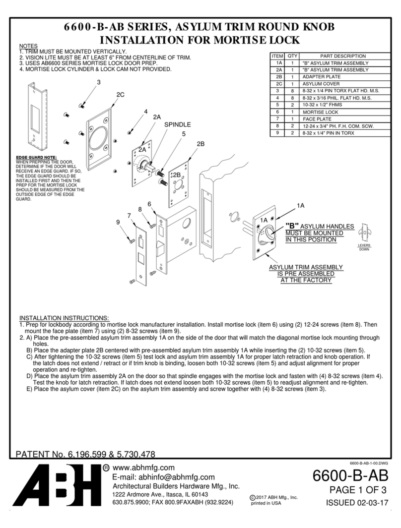
Creone KeEYBOX KEYRACK KEYWIN5 User manual

KEYWIN5
Installation guide

KeyWin 5 manual, Version 1.0.0. All and copyright reserved by Creone AB 2
Creone AB
Creone offers simple and flexible solutions for key management
and value storage. Creone offers everything from simple cabinets
with lockers and normal key hooks to smart key management
systems in which each key is identified and all events are recorded
and logged.
Creone delivers Keyboxes and Valueboxes to 25 countries in Eu-
rope, North America and Central America. Its manufacturing division
and headquarters are located in Tranas, Sweden.
For more information about Creone and our products,
visit www.creone.com.
CREONE AB
Telephone: +46 (0) 140 - 38 61 80
E-mail: [email protected]
Address: Malmgatan 8, Tranås
Post address: Creone AB, Box 148, 573 22 Tranas, Sweden
www.creone.com

KeyWin 5 manual, Version 1.0.0. All and copyright reserved by Creone AB 3
DELIVERY 4
MOUNTING KEYBOX 6
CONFIGURATION MENU 10
WIRING DIAGRAMS 14 PCB
15 KeyControl Strips
16 KeyBox 9500EC
17 Creone RFID reader
18 External reader
19 External alarm
Introduction

Delivery

4
52
3
1
KeyWin 5 manual, Version 1.0.0. All and copyright reserved by Creone AB 5
Thank you for choosing Creone!
We hope that your new Creone product will make your daily key ma-
nagement work easier, faster and more secure than before. Read
these instructions carefully before you install the system.
The system should always be installed by an trained Creone dealer.
If you have any questions, please feel free to contact us and we will
be happy to help!
YOUR DELIVERY SHOULD INCLUDE:
1. KeyWin5 USB box with complete
software and manual
2. Power cable
3. TCP/IP cable
4. IntelliPin
5. Key rings

Mounting KeyBox

KeyWin 5 manual, Version 1.0.0. All and copyright reserved by Creone AB 7
FOLLOW THE INSTRUCTIONS TO GET STARTED:
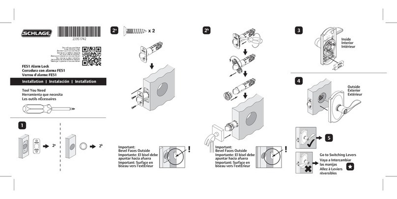
1. To open the cabinet, use the key provided to open
the service door. There you will find an emergency
release to open the door of the cabinet.
Mounting KeyBox

50
275
48
113 560
625
365
746
205
50
640
113 560
730
: 746
570
KeyWin 5 manual, Version 1.0.0. All and copyright reserved by Creone AB 8
2. Install the cabinet in the selected location. Follow the diagram below.
9500 SC
9400 SC
(mm)
(mm)

KeyWin 5 manual, Version 1.0.0. All and copyright reserved by Creone AB 9
1. Enter 1234# on the keypad to access the configuration menu. You
can find a complete description of this menu on the next page.
2. Enter the number of doors and strips the system includes.
3. Enter time/date.
4. If you will be using a fixed IP, turn the DHCP to off and go to the
next step (otherwise go to step 6)
5. Enter IP number/Netmask Gateway.
6. Choose Reboot at the bottom of the menu and confirm.
7. The cabinet will now reboot and when this has taken place confi-
guration is complete.
Quick guide - Configure your cabinet
3. Connect the power cable to the power supply 4. Connect the TCP/IP cable according the diagram on the below.
5. Connect the battery backup cable to the PCB according to
the diagram on the right. The cabinet will now start up and
you will see <Rebooting> in the display. When the display
shows <Keybox5>, the physical installation of the cabinet is
complete.

Configuration Menu

KeyWin 5 manual, Version 1.0.0. All and copyright reserved by Creone AB 11
STEP 1
Here you can give the cabinet a specific name. Note that this can
easily be modified from the KeyWin software at a later time.
STEP 2
Here you can give the cabinet a specific location, e.g. Office,
Factory etc. Note that this can easily be modified from the KeyWin
software at a later time.
STEP 3*
Here you first enter how many doors you have, confirming with #,
then how many strips you have in each door, confirming with #.
STEP 4
Here you can change the language in the cabinet. Available langu-
ages are Swedish, German, English and Russian. Please note that
the configuration menu is always in English.
STEP 5
Here the administrator can change a user’s PIN code. Enter the
valid PIN, confirming with #. Enter the new PIN and confirm with #.
Confirm the new PIN and press #.
STEP 6
Here you can activate an external unit such as an alcoreader, card
reader etc. When activating this function, the main window of the
display will be changed to LOCKED. To enter the cabinet users now
need to be authorised first via the external unit. For more informa-
tion, see the wiring diagram on page 18 of these instructions.
STEP 7
If your cabinet is equipped with an RFID reader, you must specify
the correct unit in this menu. Use the up and down arrows to find
the correct reader, and confirm the reader using #. To install your
RFID reader, see the wiring diagram on page 17 in these instruc-
tions.
Configuration menu
Follow the instructions below to set the correct settings for your
cabinet: Enter 1234# (default) on the keypad to access the con-
figuration menu of the cabinet. This is the menu that allows you
to configure your cabinet settings. You navigate through the menu
using the arrows on the keypad. Confirm using #, and cancel using
*. To erase characters, use the left arrow, and use the right arrow to
move forward. Steps marked with * are essential for your system
to work.

KeyWin 5 manual, Version 1.0.0. All and copyright reserved by Creone AB 12
STEP 8
When the correct RFID reader is connected to the cabinet and confirmed
as described above, it will be possible to test the card or badge in this
menu. Swipe the card or badge on the front of the reader to see the cor-
rect ID number in this menu. This is the number that should be entered
on the user profile to open the cabinet without a PIN code.
STEP 9
By activating this function, you will be able to connect an external alarm to
the cabinet and send the “Service Door Alarm” signal to another system.
See the wiring diagram on page 17 in these instructions.
STEP 10
By enabling “Smart Mode” for your cabinet you change the procedure for
users when opening the cabinet. When the user enters a valid PIN code,
they now need to choose whether they want to GET or RETURN a key to
the cabinet. If the user does not have a key in their possession, they will
automatically be presented with the “Fetch Key” session.
Fetch key – All keys the user has access to will be shown in the menu. By
pressing right arrow for the key, it will be marked as a key to be removed.
You can remove one or several keys. To confirm the keys, press # and the
door will open. Only the confirmed keys will be accessible for the user to
remove from the cabinet. Return key – The door will open immediately
and all keys in the possession of the user will be shown in the menu.
When a key is returned to the cabinet, the key will disappear from the
menu.
STEP 11*
Here you set the date. Erase the date with the left arrow and enter the
correct date. Confirm with #.
STEP 12*
Here you set the time. Erase the time with the left arrow and enter the
correct time. Confirm with #.
STEP 13
This function gives you as an administrator the option of unlocking all keys
in your system in an emergency. Enter # twice in this menu and all keys
will be unlocked. Then exit the menu and open the cabinet with the admin
code (default 301042#). When you close the door, all keys will return to
locked.
STEP 14
Number of List Items. Here you can choose to display 1,2 or 3 keys in the
display when user have logged in.
STEP 15
DHCP is by default activated when starting up a new cabinet. If a fixed IP
address is to be used, this should be changed to “OFF”.
STEP 16
If a fixed IP address is to be used, DH CP must first be set to “OFF”.
Then you can enter the address in this field. If using this field, ask your IT
department for the correct information.
STEP 17
When using a fixed IP address, the Netmask also needs to be set. Enter
the correct Netmask in this field and confirm by enter #. If using this field,
ask your IT department for the correct information.
STEP 18
When using a fixed IP address, the Gateway must also be set. Enter the
correct Gateway in this field and confirm with #. If using this field, ask your
IT department for the correct information.
STEG 19
Here you will see your cabinet’s software version. If you need help from
Creone’s support team, this is information they may need to know.
STEG 20
“Reboot” is used when you need to restart the cabinet. This should
always be done after you have configured “Doors & Strips”, “IP number”,
“Netmask” and “Gateway”.
STEG 21
By using “Factory reset”, all information in the cabinet will be deleted.
STEG 22
Exit Configuration.

Wiring Diagrams

13
2
4
5
6
7
8
910
C
NC
NO
Data +
Data -
GND
GENERAL IO
GPIO21
GPIO90
GPIO91
GPIO97
GND
12-15 V
1. Battery backup cable
2. Strip cable – First strip in your system (see more on next
page)
3. Strip cable – Last strip in your system (see more on next
page)
4. Solenoid 1-6 (see page 12)
5. Alarm cable 1-6 (see page 12)
6. SIMCOM
7. Connection for RFID reader (see page 15)
8. External alarm, 15 V (see page 16)
9. TCP/IP cable
10. Connection for external reader/unit (see page 17)
PCB
Explanation of circuit board parts

Keycontrol strips
Below you can find the wiring diagram for the KeyControl strips
in your system. Please note that the strip cable from the bottom
position on the PCB should be connected to the left position on the
first strip. If the cables not are connected according to the diagram
below, the system will not start up. Then you must turn off the
power, connect the cables as specified below and turn on power to
the unit again.
First door
Second door

KeyWin 5 manual, Version 1.0.0. All and copyright reserved by Creone AB 16
STEP 1
Mount the KeyBox 9500EC on the wall according according the
measurement information on page 8.
STEP 2
Disconnect the mains power to the cabinet.
STEP 3
Connect the strip cables as shown in page 15.
STEP 4
Connect the solenoid cable and alarm cable according to
picture below.
STEP 5
Turn on the power to the main cabinet. When the cabinet has started
up, enter the service PIN (default 1234#) and access the configura-
tion menu, see page 10 in these instructions.
STEP 6
Go to “Set number of doors” and enter the correct number of doors,
and the correct number of strips in each door.
STEP 7
Go to “Reboot” and confirm. When the cabinet has started up, the
expansion cabinet is ready to use.
Connecting KeyBox 9500EC
The instructions below are for when you connect KeyBox 9500EC to
an existing KeyBox 9400/9500SC. Follow the instructions carefully:
Alarm contact
Solenoid cable
Solenoid cable
Alarm contact

13
2
4
5
6
7
8
910
C
NC
NO
Data +
Data -
GND
GENERAL IO
GPIO21
GPIO90
GPIO91
GPIO97
GND
12-15 V
1. Mount the RFID reader on the service door of the cabinet.
2. Connect the four cables according to the diagram above.
3. Log in to the configuration menu with the service PIN
(default 1234#). See page 9 in these instructions.
4. Use the arrows to navigate to “Select Card Reader Type”.
Choose the correct type.
5. To test the reader, go down to “Test Card reader” and
swipe your card in front of the reader. If everything is cor-
rectly installed, you will hear a sound and see a number
on the display. This is the ID number of the badge and
the number that should be entered on the correct user
profile in the KeyWin5 software to open the cabinet with
the badge. See more information on this in the Keywin5
manual which you can find on the USB box.
RFID reader
If the RFID reader not is connected from the factory, follow the instructions below

GENERAL IO
GPIO21
GPIO90
GPIO91
GPIO97
GND
1. Mount the device on or next to the cabinet and connect
the unit according the diagram above on 3 and 6.
2. When this is done, log in to the configuration menu with
your service PIN (default 1234#) and navigate down to
“Enable external lock”. Change this to ON. See page 10
in these instructions.
3. When you exit the configuration menu, the display will
change to “LOCKED”. The user must now access the
display via the external unit. When approved, the display
will change to “Enter PIN” and the user can log in to the
cabinet.
External reader
To connect an external card reader/unit, follow the instructions below:
Connect the external card
reader on 3 and 6.

13
2
4
5
6
7
8
910
C
NC
NO
Data +
Data -
GND
GENERAL IO
GPIO21
GPIO90
GPIO91
GPIO97
GND
12-15 V
1. Connect the external alarm according to the diagram
above. INPUT 1 and NC close on alarm.
2. When the alarm has been connected, log in to the configu-
ration menu on the cabinet with your service PIN, default
1234#. Navigate down to “Enable external alarm” and
change this to ON. See page 10 in these instructions.
3. When you exit the configuration menu, the alarm has
been acitvated. Now log in to your KeyWin5 software and
configure the alarm time via SETTINGS -> CABINETS. You
can find more information in the KeyWin5 manual.
External Alarm
When connecting your KeyBox to an external alarm, you can make
sure that alarm signals generated by opening the KeyBox without a
correct PIN and when taking an intellipin without access are sent to
another system for increased security. Naturally, these alarms are
also registered in KeyWIn5 software.
Table of contents
