Crescent BA611 BA 551D User manual

BA611
www.crescentindustrial.co.uk
Operator
manual –
English

USER MANUAL ENGLISH
BA 551 - BA 551D - BA 551CD - BA 611D 909 6752 000(3)2010-03 A 1
TABLE OF CONTENTS
INTRODUCTION.............................................................................................................................................................. 2
MANUAL PURPOSE AND CONTENTS .......................................................................................................................................... 2
TARGET........................................................................................................................................................................................... 2
HOW TO KEEP THIS MANUAL....................................................................................................................................................... 2
DECLARATION OF CONFORMITY ................................................................................................................................................ 2
IDENTIFICATION DATA................................................................................................................................................................... 2
OTHER REFERENCE MANUALS................................................................................................................................................... 3
SPARE PARTS AND MAINTENANCE............................................................................................................................................. 3
CHANGES AND IMPROVEMENTS ................................................................................................................................................ 3
OPERATION CAPABILITIES ........................................................................................................................................................... 3
CONVENTIONS .............................................................................................................................................................................. 3
UNPACKING/DELIVERY ................................................................................................................................................. 3
SAFETY ........................................................................................................................................................................... 4
SYMBOLS ....................................................................................................................................................................................... 4
GENERAL INSTRUCTIONS............................................................................................................................................................ 4
MACHINE DESCRIPTION ............................................................................................................................................... 6
MACHINE STRUCTURE ................................................................................................................................................................. 6
CONTROL PANEL........................................................................................................................................................................... 8
BATTERY CHARGER DATA INSPECTION WINDOW (optional).................................................................................................... 8
ACCESSORIES/OPTIONS.............................................................................................................................................................. 9
TECHNICAL DATA........................................................................................................................................................................... 9
WIRING DIAGRAM FOR BA 551 ...................................................................................................................................................11
WIRING DIAGRAM FOR BA 451D AND BA 531D ........................................................................................................................ 12
USE ................................................................................................................................................................................ 13
BATTERY CHECK/SETTING ON A NEW MACHINE .................................................................................................................... 13
BATTERY INSTALLATION AND BATTERY TYPE SETTING (WET OR GEL) .............................................................................. 14
BEFORE MACHINE START-UP .................................................................................................................................................... 15
MACHINE START AND STOP....................................................................................................................................................... 18
MACHINE OPERATION (SCRUBBING/DRYING)......................................................................................................................... 18
TANK EMPTYING.......................................................................................................................................................................... 20
AFTER USING THE MACHINE..................................................................................................................................................... 21
MACHINE LONG INACTIVITY ...................................................................................................................................................... 21
FIRST PERIOD OF USE ............................................................................................................................................................... 21
MAINTENANCE............................................................................................................................................................. 21
SCHEDULED MAINTENANCE TABLE ......................................................................................................................................... 21
BATTERY CHARGING .................................................................................................................................................................. 22
MACHINE WORKING HOUR CHECK ......................................................................................................................................... 23
SQUEEGEE CLEANING ............................................................................................................................................................... 23
SQUEEGEE BLADE CHECK AND REPLACEMENT.................................................................................................................... 24
BRUSH/PAD CLEANING............................................................................................................................................................... 25
TANK AND VACUUM GRID WITH FLOAT CLEANING, AND COVER GASKET CHECK............................................................. 25
VACUUM SYSTEM MOTOR FILTER CLEANING......................................................................................................................... 26
SOLUTION FILTER CLEANING.................................................................................................................................................... 26
FUSE CHECK/REPLACEMENT.................................................................................................................................................... 27
BRUSH/PAD-HOLDER/CYLINDRICAL BRUSH DECK DISASSEMBLY/ASSEMBLY .................................................................. 28
DETERGENT TANK CLEANING ................................................................................................................................................... 29
ECOFLEX™ SYSTEM DRAINING ................................................................................................................................................ 29
TROUBLESHOOTING................................................................................................................................................... 30
SCRAPPING .................................................................................................................................................................. 30

ENGLISH USER MANUAL
2909 6752 000(3)2010-03 A BA 551 - BA 551D - BA 551CD - BA 611D
INTRODUCTION
NOTE
The numbers in brackets refer to the components shown in Machine Description chapter.
MANUAL PURPOSE AND CONTENTS
The purpose of this Manual is to provide the operator with all necessary information to use the machine properly, in a safe and
autonomous way. It contains information about technical data, safety, operation, storage, maintenance, spare parts and disposal.
Before performing any procedure on the machine, the operators and qualied technicians must read this Manual carefully. Contact
Nilsk in case of doubts regarding the interpretation of the instructions and for any further information.
TARGET
This Manual is intended for operators and technicians qualied to perform the machine maintenance.
The operators must not perform procedures reserved for qualied technicians. Nilsk will not be answerable for damages coming
from the non-observance of this prohibition.
HOW TO KEEP THIS MANUAL
The User Manual must be kept near the machine, inside an adequate case, away from liquids and other substances that can cause
damage to it.
DECLARATION OF CONFORMITY
The Declaration of Conformity, supplied with the machine, certies the machine conformity with the law in force.
NOTE
Two copies of the original declaration of conformity are provided together with the machine documentation.
IDENTIFICATION DATA
The machine model and serial number are marked on the plate (34).
The machine production year is written in the declaration of conformity and it is also indicated by the rst two gures of the machine
serial number.
This information is useful when requiring machine spare parts. Use the following table to write down the machine identication data.
MACHINE model ...............................................................................
MACHINE serial number ...................................................................

USER MANUAL ENGLISH
BA 551 - BA 551D - BA 551CD - BA 611D 909 6752 000(3)2010-03 A 3
OTHER REFERENCE MANUALS
Electronic Battery Charger Manual (if equipped), to be considered as integral part of this Manual
Moreover, the following Manuals are available:
Service Manual (that can be consulted at Nilsk Service Centers)–
Spare Parts List (supplied with the machine)–
SPARE PARTS AND MAINTENANCE
All necessary operating, maintenance and repair procedures must be performed by qualied personnel or by Nilsk Service
Centers.
Only original spare parts and accessories must be used.
Contact Nilsk for service or to order spare parts and accessories, specifying the machine model and serial number.
CHANGES AND IMPROVEMENTS
Nilsk constantly improves its products and reserves the right to make changes and improvements at its discretion without being
obliged to apply such benets to the machines that were previously sold.
Any change and/or addition of accessory must be approved and performed by Nilsk.
OPERATION CAPABILITIES
These scrubber-dryers are used to clean (scrubbing and drying) smooth and solid oors, in civil or industrial environment, under
safe operation conditions by a qualied operator.
The scrubber-dryers cannot be used for tted carpet and carpet cleaning.
CONVENTIONS
Forward, backward, front, rear, left or right are intended with reference to the operator’s position, that is to say in driving position
with the hands on the handlebar (2).
UNPACKING/DELIVERY
To unpack the machine, carefully follow the instructions on the packing.
When the machine is delivered, check that the packing and the machine were not damaged during transportation. In case of visible
damages, keep the packing and have it checked by the carrier that delivered it. Call the carrier immediately to ll in a damage claim.
Check that the machine is equipped with the following features:
Technical documents:1.
Scrubber-dryer User Manual•
Electronic Battery Charger Manual (if equipped)•
Scrubber-dryer Spare Parts List•
No. 1 connector for battery charger (for machines without on board battery charger)2.
No. 2 lamellar fuses3.

ENGLISH USER MANUAL
4909 6752 000(3)2010-03 A BA 551 - BA 551D - BA 551CD - BA 611D
SAFETY
The following symbols indicate potentially dangerous situations. Always read this information carefully and take all necessary
precautions to safeguard people and property.
The operator’s cooperation is essential in order to prevent injury. No accident prevention program is effective without the total
cooperation of the person responsible for the machine operation. Most of the accidents that may occur in a factory, while working
or moving around, are caused by failure to comply with the simplest rules for exercising prudence. A careful and prudent operator is
the best guarantee against accidents and is essential for successful completion of any prevention program.
SYMBOLS
DANGER!
It indicates a dangerous situation with risk of death for the operator.
WARNING!
It indicates a potential risk of injury for people or damage to objects.
CAUTION!
It indicates a caution or a remark related to important or useful functions. Pay careful attention to the
paragraphs marked by this symbol.
NOTE
It indicates a remark related to important or useful functions.
CONSULTATION
It indicates the necessity to refer to the User Manual before performing any procedure.
GENERAL INSTRUCTIONS
Specic warnings and cautions to inform about potential damages to people and machine are shown below.
DANGER!
Before performing any maintenance, repair, cleaning or replacement procedure disconnect the battery–
connector and remove the ignition key.
This machine must be used by properly trained operators only. Children or disabled people cannot use this–
machine.
Keep the battery away from sparks, ames and incandescent material. During the normal operation explosive–
gases are released.
Do not wear jewels when working near electrical components.–
Do not work under the lifted machine without supporting it with safety stands.–
Do not operate the machine near toxic, dangerous, ammable and/or explosive powders, liquids or vapours:–
This machine is not suitable for collecting dangerous powders.
Battery charging produces highly explosive hydrogen gas. Keep the tank assembly open during battery–
charging and perform this procedure in well-ventilated areas and away from naked ames.
WARNING!
Carefully read all the instructions before performing any maintenance/repair procedure.–
Before using the battery charger, ensure that frequency and voltage values, indicated on the machine serial–
number plate, match the electrical mains voltage.
Do not pull or carry the machine by the battery charger cable and never use the battery charger cable as–
a handle. Do not close a door on the battery charger cable, or pull the battery charger cable around sharp
edges or corners. Do not run the machine on the battery charger cable.
Keep the battery charger cable away from heated surfaces.–
Do not use the machine if the battery charger cable or plug is damaged. If the machine is not working as it–
should, has been damaged, left outdoors or dropped into water, return it to the Service Center.

USER MANUAL ENGLISH
BA 551 - BA 551D - BA 551CD - BA 611D 909 6752 000(3)2010-03 A 5
WARNING!
Carefully read all the instructions before performing any maintenance/repair procedure.–
Before using the battery charger, ensure that frequency and voltage values, indicated on the machine serial–
number plate, match the electrical mains voltage.
Do not pull or carry the machine by the battery charger cable and never use the battery charger cable as–
a handle. Do not close a door on the battery charger cable, or pull the battery charger cable around sharp
edges or corners. Do not run the machine on the battery charger cable.
Keep the battery charger cable away from heated surfaces.–
Do not use the machine if the battery charger cable or plug is damaged. If the machine is not working as it–
should, has been damaged, left outdoors or dropped into water, return it to the Service Center.
To reduce the risk of re, electric shock, or injury, do not leave the machine unattended when it is plugged–
in. Before performing any maintenance procedure, disconnect the battery charger cable from the electrical
mains.
Do not smoke while charging the batteries.–
To avoid any unauthorised use of the machine, remove the ignition key (if equipped).–
Do not leave the machine unattended without being sure that it cannot move independently.–
Always protect the machine against the sun, rain and bad weather, both under operation and inactivity–
condition. Store the machine indoors, in a dry place: This machine must be used in dry conditions, it must
not be used or kept outdoors in wet conditions.
Before using the machine, close all doors and/or covers.–
Do not allow to be used as a toy. Close attention is necessary when used near children.–
Use only as shown in this Manual. Use only Nilsk’s recommended accessories.–
Take all necessary precautions to prevent hair, jewels and loose clothes from being caught by the machine–
moving parts.
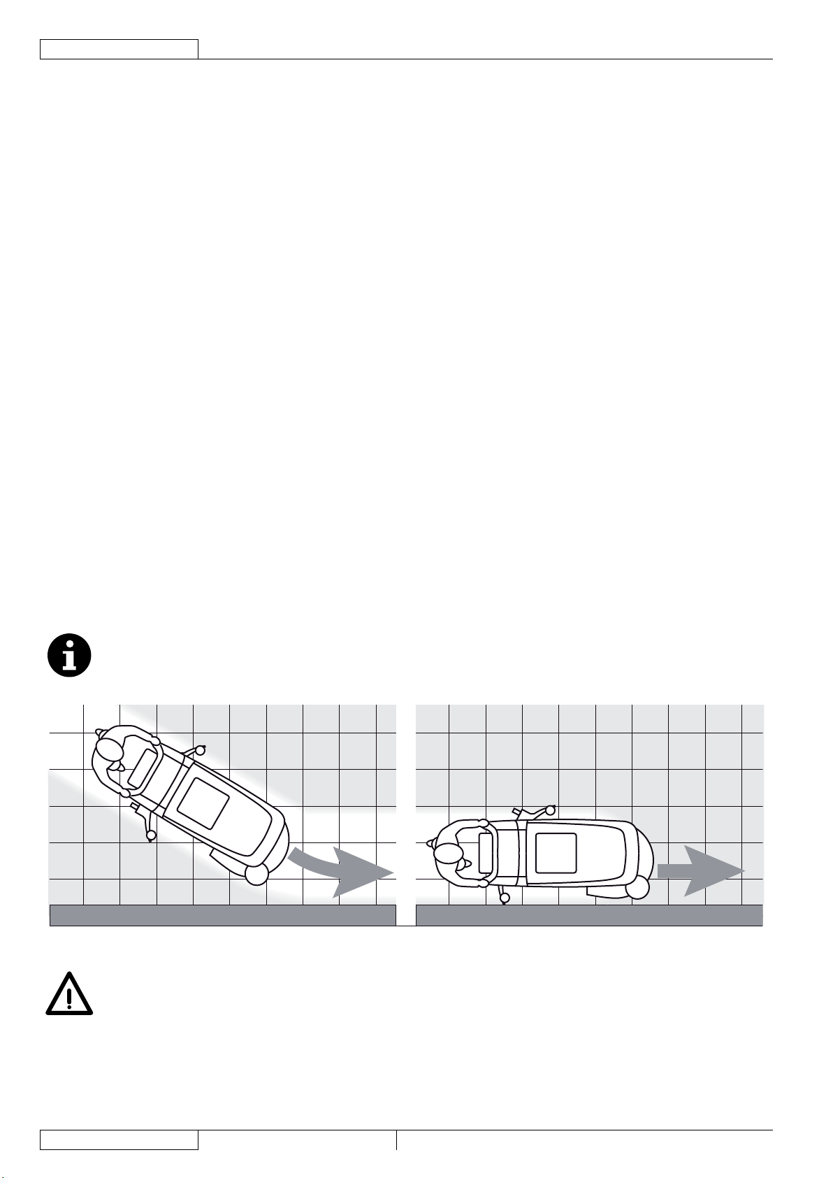
Do not use the machine on slopes with a gradient exceeding the specications.–
Do not use the machine in particularly dusty areas.–
While using this machine, take care not to cause damage to people or objects.–
Do not bump into shelves or scaffoldings, especially where there is a risk of falling objects.–
Do not lean liquid containers on the machine, use the relevant can holder.–
The machine working temperature must be between 0 °C and +40 °C.–
The machine storage temperature must be between 0 °C and +40 °C.–
The humidity must be between 30% and 95%.–
When using oor cleaning detergents, follow the instructions on the labels of the detergent bottles.–
To handle oor cleaning detergents, wear suitable gloves and protections.–
Do not use the machine as a means of transport.–
Do not allow the brushes to operate while the machine is stationary to avoid damaging the oor.–
In case of re, use a powder re extinguisher, not a water one.–
Do not tamper with the machine safety guards and follow the ordinary maintenance instructions–
scrupulously.
Do not allow any object to enter into the openings. Do not use the machine if the openings are clogged.–
Always keep the openings free from dust, hairs and any other foreign material which could reduce the air
ow.
Do not remove or modify the plates afxed to the machine.–
(Only for BA 551D, BA 551CD, BA 611D): When the machine is to be pushed for service reasons (missing or–
discharged batteries, etc.), the speed must not exceed 4 km/h.
This machine cannot be used on roads or public streets.–
Pay attention during machine transportation when temperature is below freezing point. The water in the–
recovery tank or in the hoses could freeze and seriously damage the machine.
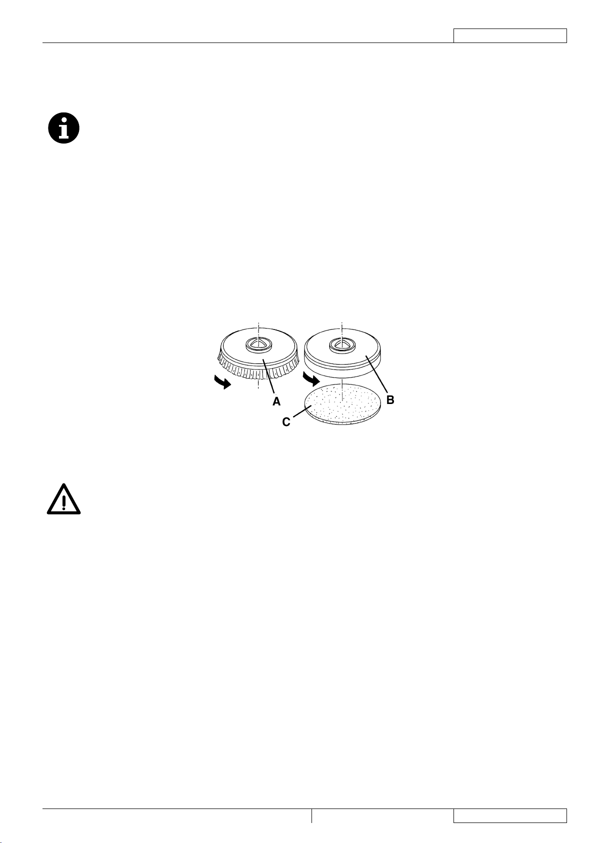
Use brushes and pads supplied with the machine and those specied in the User Manual. Using other–
brushes or pads could reduce safety.
In case of machine malfunctions, ensure that these are not due to lack of maintenance. Otherwise, request–
assistance from the authorised personnel or from an authorised Service Center.
If parts must be replaced, require ORIGINAL spare parts from an Authorised Dealer or Retailer.–
To ensure machine proper and safe operation, the scheduled maintenance shown in the relevant chapter of–
this Manual, must be performed by the authorised personnel or by an authorised Service Center.
Do not wash the machine with direct or pressurised water jets, or with corrosive substances.–
The machine must be disposed of properly, because of the presence of toxic-harmful materials (batteries,–
etc.), which are subject to standards that require disposal in special centres (see Scrapping chapter).

ENGLISH USER MANUAL
6909 6752 000(3)2010-03 A BA 551 - BA 551D - BA 551CD - BA 611D
MACHINE DESCRIPTION
MACHINE STRUCTURE
Control panel1.
Handlebar2.
Drive paddle (*)3.
Drive speed adjuster (*)4.
Battery charger data inspection window (optional)5.
Battery charger cable (optional)6.
Battery charger cable holder (optional)7.
Recovery water drain hose plug8.
Water removable ller hose (optional)9.
Squeegee lifting/lowering lever10.
Deck lifting/lowering pedal11.
Pedal position when deck is lifted11a.
Pedal position when deck is lowered11b.
Extra pressure activation (optional)11c.
Battery connector (red). This connector also works as12.
EMERGENCY push-button, to stop immediately all
functions.
Rear steering wheel13.
Driving wheels (*). Front wheels on xed axle (***)14.
Squeegee vacuum hose15.
Recovery water drain hose16.
Solution/clean water drain and level check hose17.
Deck with one brush/pad-holder18a.
Deck with two brushes/pad-holders18b.
Deck with two cylindrical brushes18c.
Brushes/pad-holders19a.
Cylindrical brushes19b.
Solution/clean water tank20.
Recovery tank21.
Recovery tank cover22.
Can holder23.
Document fastener (optional)24.
Squeegee25.
Squeegee mounting handwheels26.
Squeegee adjusting handwheel27.
Machine straight forward movement adjusting handwheel28.
Machine forward speed adjusting handwheel (***)29.
Recovery tank cover (opened to be cleaned)30a.
Recovery tank cover (completely opened)30b.
Tank cover gasket31.
Cover movable retaining plate32.
Cover xed retaining plate (do not remove!)33.
Serial number plate/technical data/conformity certication34.
Plug for squeegee vacuum hose cleaning35.
Vacuum grid with automatic shut-off oat36.
Solution front ller neck37.
Foam lter38.
Compensation hole39.
Recovery tank (open)40.
Tank lifting handle41.
Tank safety cable42.
Vacuum system motor cover43.
Vacuum system motor sound-deadening lter44.
Detergent tank (**)45.
Detergent tank ller plug (**)46.
Detergent tank handle (**)47.
Detergent feed hose (**)48.
Detergent pump (**)49.
Water pump (**)50.
Clean water lter (**)51.
Batteries52.
Battery caps53.
Solution lter (**)54.
Solution/clean water tap55.
Solenoid valve56.
Reference table for detergent proportioning (**)57.
Battery connection diagram58.
Only for(*) BA 551D, BA 551CD, BA 611D
Only for machine with EcoFlex™ system (optional)(**)
Only for(***) BA 551

USER MANUAL ENGLISH
BA 551 - BA 551D - BA 551CD - BA 611D 909 6752 000(3)2010-03 A 7
29
28
21
20
56
18a
19a
14
22
24 23 12
3
4
5
6
7
8
10
9
11c
11b
11a
11
16
17
54 55 13 26 15 12
25 27 26
19b
18c
39
30b
38
37
35
36
34
31
32
33
30a
46
53
52
18b
19a
47
58
43
42 40 41
48
44
45
47
46
50
51
49 57
48
45
S311310

ENGLISH USER MANUAL
8909 6752 000(3)2010-03 A BA 551 - BA 551D - BA 551CD - BA 611D
CONTROL PANEL
Brush/pad-holder and vacuum system switch71.
Brush/pad-holder and vacuum system switch warning light72.
Vacuum system switch73.
Vacuum system switch warning light74.
Brush/pad-holder release switch (*)75.
Brush/pad-holder release switch warning light (*)76.
Washing detergent ow control switch (**)77.
Washing detergent ow control switch warning light (**)78.
Hour counter (optional)79.
Ignition key (0 - I) (*)80.
Battery charge indicator81.
Charged battery warning light (green)81a.
Semi-discharged battery warning light (yellow)81b.
Discharged battery warning light (red)81c.
Solution ow control switches82.
Flow increase switch82a.
Flow decrease switch82b.
Solution ow indicator82c.
EcoFlex™ system switch (**)83.
EcoFlex™ system switch led indicator (**):84.
Led ON - EcoFlex™ system ON•
Led ashing - EcoFlex™ system override•
Detergent concentration level display (**)85.
Only for(*) BA 551D, BA 551CD, BA 611D
Only for machine with EcoFlex™ system (optional)(**)
BA 551
71 72 73
81a81b81c82a82c82b
74
79
81
82
BA 551D, BA 551CD, BA 611D
71 72 73
81a81b81c82a82c82b
74 75 76 84 83 78 77
79
80
81
82
85
S311311 S311312
BATTERY CHARGER DATA INSPECTION WINDOW (optional)
Electronic battery charger90.
Lead (WET) or gel (GEL) battery selector91.
Green warning light (the battery charger is on and batteries are charged)92.
Yellow warning light (the battery charger is on and batteries are semi-discharged)93.
Red warning light (the battery charger is on and it is charging the batteries)94.
94
93
92
91
90
S311313

USER MANUAL ENGLISH
BA 551 - BA 551D - BA 551CD - BA 611D 909 6752 000(3)2010-03 A 9
ACCESSORIES/OPTIONS
In addition to the standard components, the machine can be equipped with the following accessories/options, according to the
machine specic use:
GEL batteries1.
Electronic battery charger2.
Brushes and cylindrical brushes of different materials3.
Pads of different materials4.
Polyurethane squeegee blades5.
EcoFlex™6.
Front and rear wheels of different materials7.
Hour counter8.
Solution/clean water removable ller hose9.
Pocket10.
For further information concerning the optional accessories, contact an authorised Retailer.
TECHNICAL DATA
General technical data
Model
BA 551
1 brush/pad-hold-
er, without drive
system
BA 551D
1 brush/pad-
holder, with drive
system
BA 551CD
2 cylindrical
brushes, with
drive system
BA 611D
2 brushes/pad-
holders, with drive
system
Machine height 1,088 mm
sertil85yticapacknatretawnaelc/noituloS
Recovery tank capacity 60 litres
Front wheel diameter 250 mm
Front wheel specic pressure on the mm/N2.1roo 2- 4.6 N/mm2
Rear wheel diameter 100 mm
Vacuum system motor power 330 W
W002—rewoprotommetsysevirD
h/mk6.5ot0—)elbairav(deepsevirD
Gradeability 2 %
)A(Bd3±)A(Bd8.56)ApL()1784OSI,10211OSI(noitatskrowtalevelerusserpdnuoS
)A(Bd48)AwL()1784OSI,4473OSI(levelerusserpdnuosenihcaM
s/m5.2<)1-9435OSI(smras’rotarepoehttalevelnoitarbiV 2
h5/hA011V42)V21x2(:LEGseirettabdradnatS
mm003x053x053)thgiehxhtgnelxhtdiw(ezistnemtrapmocyrettaB
Hmm550,1yticapactiucricmetsysmuucaV 2O

ENGLISH USER MANUAL
10 909 6752 000(3)2010-03 A BA 551 - BA 551D - BA 551CD - BA 611D
Technical data for machines with brush/pad-holder deck
Model
BA 551
1 brush/pad-hold-
er, without drive
system
BA 551D
1 brush/pad-
holder, with drive
system
BA 611D
2 brushes/pad-
holders, with drive
system
Cleaning width 530 mm 530 mm 610 mm
Squeegee width 760 mm 810 mm
Machine maximum length 1,323 mm 1,311 mm
mm646mm145eegeeuqstuohtiwhtdiwenihcaM
Brush diameter 530 mm 305 mm
gk201gk88sknatytpmehtiwdnaseirettabtuohtiwthgieW
gk052gk632sknatllufdnaseirettabhtiwthgiewmumixaM
Brush motor power W053W084
Brush speed 153 rpm 230 rpm
gk5.02ffodenrutnoitcnuferusserp-artxehtiwerusserpredloh-dap/hsurB
gk8.72nodenrutnoitcnuferusserp-artxehtiwerusserpredloh-dap/hsurB
Technical data for machines with cylindrical brush deck
Model BA 551CD
2 cylindrical brushes, with drive system
Cleaning width 510 mm
Squeegee width 760 mm
Machine maximum length 1,253 mm
Machine width without squeegee 575.5 mm
mm584x011)htgnelxretemaid(ezishsurblacirdnilyC
gk211sknatytpmehtiwdnaseirettabtuohtiwthgieW
gk062sknatllufdnaseirettabhtiwthgiewmumixaM
Brush motor power 400 W
Cylindrical brush speed 570 rpm
Cylindrical brush pressure 26.5 kg

USER MANUAL ENGLISH
BA 551 - BA 551D - BA 551CD - BA 611D 909 6752 000(3)2010-03 A 11
WIRING DIAGRAM FOR BA 551
Key
BAT 24 V battery
C1 Battery connector
C2 Battery charger connector
CH Battery charger (optional)
CS Deck connector
EB1 Function electronic board
ES1 Brush motor electromagnetic switches
ES2 Vacuum system relay
EV1 Water solenoid valve
F1 Deck fuse
F2 Vacuum system fuse
F4 Signal circuit fuse
HM Hour counter (optional)
M1 Brush/pad-holder motor
M2 Vacuum system motor
Only for machines without on-board battery charger(*)
Colour codes
BK Black
BU Blue
BN Brown
GN Green
GY Grey
OG Orange
PK Pink
RD Red
VT Violet
WH White
YE Yellow
(*)
S311314

ENGLISH USER MANUAL
12 909 6752 000(3)2010-03 A BA 551 - BA 551D - BA 551CD - BA 611D
(*)
(**)
(***)
S3113332
WIRING DIAGRAM FOR BA 451D AND BA 531D
Key
BAT 24 V battery
C1 Battery connector
C2 Battery charger connector
CH Battery charger (optional)
CSC Cylindrical brush deck secondary connector
EB1 Function electronic board
EB2 Drive system electronic board
ES1 Brush motor electromagnetic switches
ES2 Vacuum system relay
EV1 Detergent solenoid valve (optional)
F1 Deck fuse
F2 Vacuum system fuse
F3 Drive system fuse
F4 Signal circuit fuse
F5 Brush/pad-holder release fuse
F6 Pump fuse
HM Hour counter (optional)
K1 Ignition key
M1 Brush/pad-holder motor
M2 Vacuum system motor
M3 Drive system motor
M4 Water pump (optional)
M5 Detergent pump (optional)
RV1 Speed potentiometer
RV2 Maximum speed potentiometer
SW1 Brush/drive system enabling microswitch
Only for machine with wheel diameter of 250 mm(*)
Only for machines with cylindrical brush deck(**)
Only for machines without on-board battery charger(***)
Colour codes
BK Black
BU Blue
BN Brown
GN Green
GY Grey
OG Orange
PK Pink
RD Red
VT Violet
WH White
YE Yellow

USER MANUAL ENGLISH
BA 551 - BA 551D - BA 551CD - BA 611D 909 6752 000(3)2010-03 A 13
USE
WARNING!
On some points of the machine there are some adhesive plates indicating:
DANGER–
WARNING–
CAUTION–
CONSULTATION–
While reading this Manual, the operator must pay particular attention to the symbols shown on the plates.
Do not cover these plates for any reason and immediately replace them if damaged.
BATTERY CHECK/SETTING ON A NEW MACHINE
WARNING!
The electric components of the machine can be seriously damaged if the batteries are either improperly installed
or connected. The batteries must be installed by qualied personnel only. Set the function electronic board and
the battery charger (optional) according to the type of batteries used (WET or GEL).
Check the batteries for damage before installation.
Disconnect the battery connector and the battery charger plug.
Handle the batteries with great care.
Install the battery terminal protection caps supplied with the machine.
The machine requires two 12 V batteries, connected according to the diagram (58).
The machine can be supplied in one of the following modes:
Batteries (WET or GEL) already installed and ready to be used
Check that the batteries are connected to the machine with the connector (12).1.
(Only for2. BA 551D, BA 551CD, BA 611D): Insert the ignition key (80) and turn it to “I”.
(Only for BA 551): Turn on the machine by pressing the switch (71) and/or (73).
If the green warning light (81a) turns on, the batteries are ready to be used.
If the yellow or red warning light (81b or 81c) turns on, the batteries must be charged (see the procedure in Maintenance
chapter).
Batteries (WET) installed on the machine, but without electrolyte
Open the cover (22) and check that the recovery tank (21) is empty, otherwise empty it with the drain hose (16).1.
Grasp the handle (41) and carefully lift the tank (40).2.
Remove the caps (53) of the batteries (52).3.
WARNING!
Pay attention when using sulphuric acid, as it is corrosive. If it comes in contact with skin or eyes, rinse
thoroughly with water and consult a physician.
Batteries have to be lled in a well-ventilated area. Wear protective gloves.
Fill up the battery cells with sulphuric acid for batteries (density 1.27 to 1.29 kg at 25 °C) in accordance with the instructions4.
shown in the Battery Manual. The correct quantity of sulphuric acid is shown in the Battery Manual.
To avoid damaging the oor, dry with a cloth both acid and water on the top of the batteries after charging.5.
Let the batteries rest and ll in with sulphuric acid in accordance with the instructions shown in the Battery Manual.6.
Charge the batteries (see the procedure in Maintenance chapter).7.
Without batteries
Buy appropriate batteries (see the Technical Data paragraph).1.
For battery choice and installation, apply to qualied battery Retailers.2.
Set the machine and the battery charger (if equipped) according to the type of batteries installed (WET or GEL), according to3.
the procedure shown in the following paragraph.

ENGLISH USER MANUAL
14 909 6752 000(3)2010-03 A BA 551 - BA 551D - BA 551CD - BA 611D
BATTERY INSTALLATION AND BATTERY TYPE SETTING (WET OR GEL)
Set the electronic board of the machine and of the battery charger (if equipped) according to the type of batteries installed (WET or
GEL) as shown below:
Machine setting (only for BA 551)
Press the switch (71) or (73) and pay attention to the following in the very rst seconds of machine operation:1.
If the green warning light (81a) is ashing, the machine is set to GEL.•
If the red warning light (81c) is ashing, the machine is set to WET.•
If the setting is to be changed, perform the following procedure.2.
Turn off the machine by pressing the switch (71) and/or (73).3.
Press and hold the switches (71) and (73) at the same time.4.
Release the switches (71) and (73) at least 8 seconds after starting the machine.5.
Within 3 seconds, press the switch (73) again for a few seconds and check that the warning light for the required setting is6.
ashing (as shown in step 1).
Machine setting (only for BA 551D, BA 551CD, BA 611D)
Turn the ignition key (80) to “I” and pay attention to the following in the very rst seconds of machine operation:1.
If the green warning light (81a) is ashing, the machine is set to GEL.•
If the red warning light (81c) is ashing, the machine is set to WET.•
If the setting is to be changed, perform the following procedure.2.
Turn off the machine by turning the ignition key (80) to “0”.3.
Press and hold the switches (71) and (73) at the same time, then turn the ignition key (80) to “I”.4.
Release the switches (71) and (73) at least 8 seconds after starting the machine.5.
Within 3 seconds, press the switch (73) again for a few seconds and check that the warning light for the required setting is6.
ashing (as shown in step 1).
Battery charger setting (for machines with on-board battery charger)
Remove the battery charger data inspection window screws (A, Fig. 1).1.
Remove the window (B).2.
Turn the battery charger selector (C) to WET for lead batteries, or to GEL for gel batteries.3.
Install the window (B) and tighten the screws (A).4.
Battery installation
Open the cover (22) and check that the recovery tank (21) is empty, otherwise empty it with the drain hose (16).1.
Grasp the handle (41) and carefully lift the tank (40).2.
Install the batteries.3.
Battery charging
Charge the batteries (see the procedure in Maintenance chapter).1.
C
A
A
B
Figure 1
S311316

USER MANUAL ENGLISH
BA 551 - BA 551D - BA 551CD - BA 611D 909 6752 000(3)2010-03 A 15
BEFORE MACHINE START-UP
Deck installation/removal
The machine can be equipped with either the brush/pad-holder deck (18a and 18b) or the cylindrical brush deck (18c).
For deck installation/removal see the procedure in Maintenance chapter.
NOTE
When the deck is installed/removed, it may be necessary to change the squeegee too, because they must have the
same width. For correct matching of deck and squeegee, see the Squeegee Installation paragraph.
Brush/pad-holder installation/removal
According to the kind of cleaning to be performed, the machine can be equipped either with brushes (A, Fig. 2) or pad-holders1.
(B) with pads (C) together with the appropriate deck.
(Only for2. BA 551D, BA 551CD, BA 611D): Turn the ignition key (80) to “0”.
(Only for BA 551): Turn off the machine by pressing the switch (71) and/or (73).
If equipped, turn the speed adjuster (4) to idle by turning it counter-clockwise.3.
Place the brushes (A) or the pad-holders (B) under the appropriate deck (18a) or (18b).4.
Lower the deck on the brushes/pad-holders by pressing the pedal (11).5.
(Only for6. BA 551D, BA 551CD, BA 611D): Turn the ignition key (80) to “I”.
Press the brush/pad-holder and vacuum system switch (71).7.
Slightly press the paddle (3) forward to engage the brushes/pad-holders, then release it. If necessary, repeat the procedure8.
until the brushes/pad-holders are engaged.
Figure 2
S311317
WARNING!
(Only for BA 551D, BA 551CD, BA 611D): Do not press the paddle (3) completely, otherwise the machine will start
moving.
A slight pressure on the paddle (3) is enough to engage the brushes/pad-holders and to turn on the relevant
motors.
To remove the brushes/pad-holders, the deck must be lifted by pressing the pedal (11), then press the switch (75) (if equipped)9.
and wait for the brush/pad-holder to fall on the oor.
(Only for BA 551D, BA 551CD, BA 611D): Turn the ignition key (80) to “0”.
(Only for BA 551): Press the switch (71).
If the machine is not equipped with the automatic release system (switch 75), manually remove the brush/pad-holder from the
hub, by turning it in the opposite direction to the normal rotation direction.

ENGLISH USER MANUAL
16 909 6752 000(3)2010-03 A BA 551 - BA 551D - BA 551CD - BA 611D
Available brushes and their relevant application guides (suggestions only)
XIMNOINUETILORPENELORP042TIRGDIM081TIRGETILDIMsledoM
General cleaning:
Concrete
Terrazzo oor
Ceramic tiles/quarrystones
Marble
Vinyl tiles
Rubber tiles
Polishing:
Rubber tiles
Marble
Vinyl tiles
Cylindrical brush installation/removal (only for BA 551CD)
Turn the ignition key (80) to “0”.1.
Lift the cylindrical brush deck by pressing the pedal (11).2.
Remove the handwheels (A, Fig. 3) and the lids (B) by pushing them downwards and pressing on the handwheels.3.
Install the cylindrical brushes (C).4.
The cylindrical brushes can be installed on either sides.
Install the lids (B) and fasten them with the handwheels (A).5.
To remove the cylindrical brushes, perform steps 1 to 5 in the reverse order.6.
A
B
C
DE
A
C
B
Figure 3
S311318
Available cylindrical brushes and their relevant application guides (suggestions only)
54.0NOLYNTFOS06.0NOLYNDRAH04.0ENELYPORPYLOPsledoM
General cleaning:
Concrete
Terrazzo oor
Ceramic tiles/quarrystones
Marble
Vinyl tiles
Rubber tiles

USER MANUAL ENGLISH
BA 551 - BA 551D - BA 551CD - BA 611D 909 6752 000(3)2010-03 A 17
Squeegee installation
Install the squeegee (25) and fasten it with the handwheels (26), then connect the vacuum hose (15) to the squeegee.1.
With the handwheel (27), adjust the squeegee so that the rear blade - in all its length - touches the oor and the front blade is2.
slightly detached from the oor.
Guide to match squeegees and brush/pad-holder decks
ledomeegeeuqSledomkceD
mm067htdiw,)6.giF(muinimulAmm035:retemaidhsurb,)a81(hsurbenohtiwkceD
mm018htdiw,)7.giF(leetSmm503:retemaidhsurb,)b81(sehsurbowthtiwkceD
Deck with two cylindrical brushes (18c), brush length: 485 mm Aluminium (Fig. 6), width 760 mm
Solution or washing water tank lling
NOTE
If the machine is equipped with EcoFlex™ system (optional) (switches (83 and 77) activated) pour clean water in the
tank, otherwise pour solution.
Open the ller neck (8).1.
(For machine without EcoFlex™ system)2.
Fill the tank (20) with a solution suitable for the work to be performed.
Do not ll the solution tank completely, leave a few centimetres from the edge.
Always follow the dilution instructions on the label of the chemical product used to prepare the solution.
The solution temperature must not exceed 40 °C.
CAUTION!
Use only low-foam and non-ammable detergents, intended for automatic scrubber applications.
(For machine with EcoFlex™ system)
Fill the tank (20) with clean water.
Do not ll the clean water tank completely, leave a few centimetres from the edge.
The water temperature must not exceed 40 °C.
Detergent tank lling
(For machine with EcoFlex™ system)
Open the cover (22) and check that the recovery tank (21) is empty, otherwise empty it with the drain hose (16).1.
Grasp the handle (41) and carefully lift the tank (40).2.
Open the plug (46).3.
Fill the tank (45) with a detergent suitable for the work to be performed (highly concentrated detergent).4.
Do not ll the detergent tank completely, leave a few inches from the edge.
CAUTION!
Use only low-foam and non-ammable detergents, intended for automatic scrubber applications.
NOTE
If the detergent hose (48) is empty (in case of new system, system emptied for cleaning, etc.), in order to ll the hose
quickly, it may be useful to drain EcoFlex™ system once or several times (see the procedure in Maintenance chapter).

ENGLISH USER MANUAL
18 909 6752 000(3)2010-03 A BA 551 - BA 551D - BA 551CD - BA 611D
MACHINE START AND STOP
Starting the machine
Prepare the machine as shown in the previous paragraph.1.
(Only for2. BA 551D, BA 551CD, BA 611D): Turn the ignition key (80) to “I”.
(Only for BA 551): Turn on the machine by pressing the switch (71) and/or (73).
Check that the green warning light (81a) turns on (charged batteries).
If the yellow or red warning light (81b or 81c) turns on, turn the ignition switch back to “0” and charge the batteries (see the
procedure in Maintenance chapter).
Drive the machine to the working place:3.
By pushing it with the hands on the handlebar (2) (only for• BA 551).
By starting it with the hands on the handlebar (2) and pushing the paddle (3) forward to move forward, and backwards to•
move in reverse (only for BA 551D, BA 551CD, BA 611D).
The maximum forward speed can be adjusted with the adjuster (4).
Lower the squeegee (25) with the lever (10).4.
Lower the brush/pad-holder deck by pressing the pedal (11).5.
Press the brush/pad-holder and vacuum system switch (71).6.
Press the solution ow control switches (82) as necessary, depending on the type of cleaning to be performed.7.
Start cleaning, by moving the machine as shown in step 3. If necessary, adjust the maximum speed with the adjuster (4).8.
Stopping the machine
Stop the machine with the handlebar (2) (only for9. BA 551).
Stop the machine by releasing the paddle (3) (only for BA 551D, BA 551CD, BA 611D).
Turn off the brushes and the vacuum system by pressing the switches (71 and 73).10.
Lift the brush/pad-holder deck by pressing the pedal (11).11.
Lift the squeegee (25) with the lever (10).12.
Make sure that the machine cannot move independently.13.
MACHINE OPERATION (SCRUBBING/DRYING)
Start the machine as shown in the previous paragraph.1.
If necessary, press the solution ow control switches (82) as necessary, depending on the type of cleaning to be performed.2.
If necessary, stop the machine and adjust the squeegee balancing handwheel (27).3.
If necessary, stop the machine and turn the adjusting handwheel (28); when turning it clockwise or counter-clockwise the4.
machine forward speed can be adjusted.
(Only for5. BA 551): If necessary, stop the machine and turn the forward speed adjusting handwheel (29) as shown below:
Turn it counter-clockwise to increase the forward speed;•
Turn it clockwise to decrease the forward speed.•
NOTE
For correct scrubbing/drying of oors at the sides of the walls, Nilsk suggests to go near the walls with the right side of
the machine as shown in gure 4.
A
B
Figure 4
P100300
CAUTION!
To avoid any damage to the oor surface, turn off the brushes/pad-holders when the machine stops in one
place, especially when the extra pressure function is on.

USER MANUAL ENGLISH
BA 551 - BA 551D - BA 551CD - BA 611D 909 6752 000(3)2010-03 A 19
Adjustment of the detergent concentration in the solution
(For machine with EcoFlex™ system)
The system used to mix the detergent with the washing water can be activated by pressing the detergent ow control switch (A, Fig.
5): when the led indicator (B) is ON, the detergent is added to the washing water.
The display (C) shows the detergent concentration level (1 to 6) in the solution: for the related percentage values refer to the table
(D).
In order to change the actual detergent concentration, proceed as follows:
Turn off the detergent ow control switch (A) (the led indicator (B) must be OFF).1.
Press and hold the detergent ow control switch (A) until the led indicator (B) ashes.2.
Release the switch (A). Press it again shortly to go to the next level shown by the display (C); repeat the operation until the3.
desired setting is reached.
Wait until the led indicator (B) stops ashing: the new level is now set.4.
NOTE
Detergent percentage setting is stored into memory, even if the machine is turned off.
EcoFlex™ switch
Press the EcoFlex™switch (E, Fig. 5) whenever you temporarily need a greater washing power.
When you press the switch (E) (the led indicator (F) is ashing) the solution ow increases (for machine with EcoFlex™ system)
and the detergent concentration in the solution increases (moreover, if the detergent mixing function is not activated, it is
automatically activated).
The original settings can be restored by pressing the switch (E) once again (the led indicator (F) is ON).
NOTE
If the switch (E) is not pressed once again, the original settings are restored automatically after 60 seconds.
B
A
E
F
C
D
Figure 5
S311318
This manual suits for next models
3
Table of contents
Other Crescent Scrubber manuals

Crescent
Crescent SC800 Operating instructions

Crescent
Crescent SC6000 Operating instructions

Crescent
Crescent SC2000 Operating instructions

Crescent
Crescent SC530 53 B GO User manual

Crescent
Crescent CS7010 User manual

Crescent
Crescent BR855 Operating instructions

Crescent
Crescent CS7010 User manual

Crescent
Crescent SC8000 Operating instructions

Crescent
Crescent SC351 Operating instructions

Crescent
Crescent SC6500 User manual