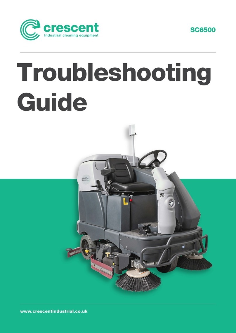
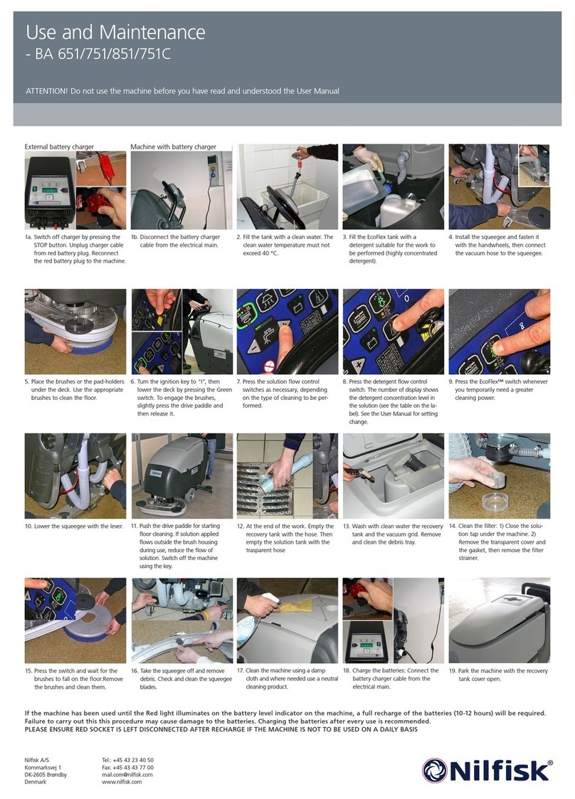
Crescent SC6500 User manual

SC6500
www.crescentindustrial.co.uk
Service
Manual

Contents 2Service Manual – SC6500™
Contents
Service Manual . . . . . . . . . . . . . . . . . . . . . . . . . . . . . . . . . . . . . . . . . 1
General Information . . . . . . . . . . . . . . . . . . . . . . . . . . . . . . . . . . . . . 9
General Machine Description . . . . . . . . . . . . . . . . . . . . . . . . . . . . . . . . . 9
Service Manual Purpose and Application . . . . . . . . . . . . . . . . . . . . . . . . . . . 9
Conventions . . . . . . . . . . . . . . . . . . . . . . . . . . . . . . . . . . . . . . . 9
Feedback . . . . . . . . . . . . . . . . . . . . . . . . . . . . . . . . . . . . . . . . . 9
Revision History . . . . . . . . . . . . . . . . . . . . . . . . . . . . . . . . . . . . . . . . 9
Other Manuals and Information Sources . . . . . . . . . . . . . . . . . . . . . . . . . . . 9
Electronic Databases . . . . . . . . . . . . . . . . . . . . . . . . . . . . . . . . . . 9
Manuals . . . . . . . . . . . . . . . . . . . . . . . . . . . . . . . . . . . . . . . . . 9
Parts and Service. . . . . . . . . . . . . . . . . . . . . . . . . . . . . . . . . . . . . . . .10
Nameplate . . . . . . . . . . . . . . . . . . . . . . . . . . . . . . . . . . . . . . . . . . . 10
Transporting the Machine . . . . . . . . . . . . . . . . . . . . . . . . . . . . . . . . . . . 10
Towing . . . . . . . . . . . . . . . . . . . . . . . . . . . . . . . . . . . . . . . . . . . . . 11
Caution and Warning Symbols . . . . . . . . . . . . . . . . . . . . . . . . . . . . . . . . 11
General Safety Instructions . . . . . . . . . . . . . . . . . . . . . . . . . . . . . . . . . . 11
Emergency-stop Switch/Battery Disconnect . . . . . . . . . . . . . . . . . . . . . . . . . 13
Technical Specications (As Installed and Tested On The Unit) . . . . . . . . . . . . . . 14
Advance Brand SC6500 Models . . . . . . . . . . . . . . . . . . . . . . . . . . . . .14
Nilsk Brand SC6500 Models . . . . . . . . . . . . . . . . . . . . . . . . . . . . . .16
Dimensions . . . . . . . . . . . . . . . . . . . . . . . . . . . . . . . . . . . . . . . . . . . 18
General Machine Overview . . . . . . . . . . . . . . . . . . . . . . . . . . . . . . . . . . 19
Major Machine Components. . . . . . . . . . . . . . . . . . . . . . . . . . . . . . .19
Control Panel. . . . . . . . . . . . . . . . . . . . . . . . . . . . . . . . . . . . . . .21
Switch and Button Functions . . . . . . . . . . . . . . . . . . . . . . . . . . . .21
Control Panel Indicators . . . . . . . . . . . . . . . . . . . . . . . . . . . . . . 24
Control Panel Display . . . . . . . . . . . . . . . . . . . . . . . . . . . . . . . .26
Caution Displays . . . . . . . . . . . . . . . . . . . . . . . . . . . . . . . . . . 26
Circuit Breakers . . . . . . . . . . . . . . . . . . . . . . . . . . . . . . . . . . .27
General Maintenance . . . . . . . . . . . . . . . . . . . . . . . . . . . . . . . . . . . . . 27
Maintenance After Use . . . . . . . . . . . . . . . . . . . . . . . . . . . . . . . . . 27
Maintenance Schedule. . . . . . . . . . . . . . . . . . . . . . . . . . . . . . . . . .28
Machine Lubrication. . . . . . . . . . . . . . . . . . . . . . . . . . . . . . . . . . .29
Lubrication Points . . . . . . . . . . . . . . . . . . . . . . . . . . . . . . . . . . . . 29
PM Check List - SC6500 . . . . . . . . . . . . . . . . . . . . . . . . . . . . . . . . . . . . 30
Chassis System . . . . . . . . . . . . . . . . . . . . . . . . . . . . . . . . . . . . . . . 32
Major Chassis Components . . . . . . . . . . . . . . . . . . . . . . . . . . . . . . . . . .32
Control System . . . . . . . . . . . . . . . . . . . . . . . . . . . . . . . . . . . . . . . 33
Functional Description . . . . . . . . . . . . . . . . . . . . . . . . . . . . . . . . . . . . 33
Overview . . . . . . . . . . . . . . . . . . . . . . . . . . . . . . . . . . . . . . . . . 33
A2 Control Board Assembly. . . . . . . . . . . . . . . . . . . . . . . . . . . . .33
A3 Switch/Display Panel Assembly. . . . . . . . . . . . . . . . . . . . . . . . .34
Circuit Description. . . . . . . . . . . . . . . . . . . . . . . . . . . . . . . . . . . .34
Main Control Programming Options . . . . . . . . . . . . . . . . . . . . . . . . . . . . . 34
Fault Recall Mode . . . . . . . . . . . . . . . . . . . . . . . . . . . . . . . . . . . . 34
To Select the Battery Used in the Machine. . . . . . . . . . . . . . . . . . . . . . .35
To Restore the Scrub Pressures to the Factory Default Settings . . . . . . . . . . .35
To Enable/Disable the Fault Detection . . . . . . . . . . . . . . . . . . . . . . . . .35
To Display the Control Board Revision Level . . . . . . . . . . . . . . . . . . . . . 36
Monitor Mode . . . . . . . . . . . . . . . . . . . . . . . . . . . . . . . . . . . . . . 36
Scrub Deck Down Time Adjustment . . . . . . . . . . . . . . . . . . . . . . . . . . 36

Contents 3Service Manual – SC6500™
Normal (Light) Scrub Setting Adjustment . . . . . . . . . . . . . . . . . . . . . . . 37
Heavy Scrub Setting Adjustment . . . . . . . . . . . . . . . . . . . . . . . . . . . . 38
Extreme Scrub Setting Adjustment. . . . . . . . . . . . . . . . . . . . . . . . . . .38
Scrub Speed Switch Lockout . . . . . . . . . . . . . . . . . . . . . . . . . . . . . . 39
Detergent System Selection Mode . . . . . . . . . . . . . . . . . . . . . . . . . . . 40
EcoFlex™Mode Selection . . . . . . . . . . . . . . . . . . . . . . . . . . . . . . . . 40
Vacuum Motor Conguration Option . . . . . . . . . . . . . . . . . . . . . . . . . .40
Recovery Tank Full Detection Enable/Disable . . . . . . . . . . . . . . . . . . . . . 41
Solution Flow in Reverse Enable/Disable. . . . . . . . . . . . . . . . . . . . . . . .41
Indicator LED Intensity Selection Option . . . . . . . . . . . . . . . . . . . . . . .42
Detergent and Solution Pump Purge . . . . . . . . . . . . . . . . . . . . . . . . . . 42
Method 1 . . . . . . . . . . . . . . . . . . . . . . . . . . . . . . . . . . . . . . .42
Method 2 (as described in the Instructions for Use) . . . . . . . . . . . . . . . . 42
Side Broom Function . . . . . . . . . . . . . . . . . . . . . . . . . . . . . . . . . . 43
Side Broom Height Adjustment . . . . . . . . . . . . . . . . . . . . . . . . . . . . .43
Display Mode Selection . . . . . . . . . . . . . . . . . . . . . . . . . . . . . . . . .44
Service Test Mode . . . . . . . . . . . . . . . . . . . . . . . . . . . . . . . . . . . . . . . 44
To Enter the Service Test Mode . . . . . . . . . . . . . . . . . . . . . . . . . . . . .44
Service Test Mode Display . . . . . . . . . . . . . . . . . . . . . . . . . . . . . . . 44
Control Panel Switch and Button Functions . . . . . . . . . . . . . . . . . . . . . . 45
Troubleshooting . . . . . . . . . . . . . . . . . . . . . . . . . . . . . . . . . . . . . . . . 46
Error Indicator and Error Code Display . . . . . . . . . . . . . . . . . . . . . . . . 46
Error Codes . . . . . . . . . . . . . . . . . . . . . . . . . . . . . . . . . . . . . . . 47
Removal and Installation . . . . . . . . . . . . . . . . . . . . . . . . . . . . . . . . . . .53
A2 Control Board Assembly . . . . . . . . . . . . . . . . . . . . . . . . . . . . . . .53
Specications . . . . . . . . . . . . . . . . . . . . . . . . . . . . . . . . . . . . . . . . . .54
I/O Table with Shop Measurements . . . . . . . . . . . . . . . . . . . . . . . . . . . . . .55
A2 Control Board Assembly . . . . . . . . . . . . . . . . . . . . . . . . . . . . . . .55
Electrical System . . . . . . . . . . . . . . . . . . . . . . . . . . . . . . . . . . . . . . 59
Functional Description . . . . . . . . . . . . . . . . . . . . . . . . . . . . . . . . . . . . 59
Overview . . . . . . . . . . . . . . . . . . . . . . . . . . . . . . . . . . . . . . . . . 59
Low-voltage Cut-out Feature . . . . . . . . . . . . . . . . . . . . . . . . . . . . . . . . . 59
Battery Condition Indicator . . . . . . . . . . . . . . . . . . . . . . . . . . . . . . . . . .59
Component Locations . . . . . . . . . . . . . . . . . . . . . . . . . . . . . . . . . . . . . 61
Battery Location . . . . . . . . . . . . . . . . . . . . . . . . . . . . . . . . . . . . . 63
Connector Pin-Outs . . . . . . . . . . . . . . . . . . . . . . . . . . . . . . . . . . .64
J1 Connects to A2 Control Board . . . . . . . . . . . . . . . . . . . . . . . . . .64
J2 Connects to A2 Control Board . . . . . . . . . . . . . . . . . . . . . . . . . .65
J3 Connects to A3 Display Panel . . . . . . . . . . . . . . . . . . . . . . . . . . 65
X6 Connects to A1 Speed Controller . . . . . . . . . . . . . . . . . . . . . . . . 66
X7 Connects to Drive Motor. . . . . . . . . . . . . . . . . . . . . . . . . . . . .67
X8 Connector for Curtis Programmer . . . . . . . . . . . . . . . . . . . . . . . 67
X10 . . . . . . . . . . . . . . . . . . . . . . . . . . . . . . . . . . . . . . . . . .67
X12 Connects to H2 Flashing Lamp X11 . . . . . . . . . . . . . . . . . . . . . .68
X13 connects to M12 Solution Control Pump X14 . . . . . . . . . . . . . . . . .68
X16 Connects to L1 Solution Solenoid Valve X15 . . . . . . . . . . . . . . . . . 68
X20 Connects to M3 Squeegee Actuator X19 . . . . . . . . . . . . . . . . . . . .69
X29 Connects to M7 Left Side Broom Motor X27 . . . . . . . . . . . . . . . . . 70
X30 Connects to M8 Right Side Broom Motor X28. . . . . . . . . . . . . . . . .70
X32 . . . . . . . . . . . . . . . . . . . . . . . . . . . . . . . . . . . . . . . . . . 70
X41 Connects to R2 Scrub Deck Sensing Resistor X40 . . . . . . . . . . . . . . 71
X43 Connects to S5 Solution Tank Float Switch X42 . . . . . . . . . . . . . . . 71
X49 Connects to X48 Connector of Vacuum Motor Wiring Harness . . . . . . . 71
X51 . . . . . . . . . . . . . . . . . . . . . . . . . . . . . . . . . . . . . . . . . .72
X55 Connects to M15 Accessory Pump (Optional) X54 . . . . . . . . . . . . . . 72
X59 Connects to Telematics Connector Jumper X59A . . . . . . . . . . . . . . .72

Contents 4Service Manual – SC6500™
X59A Telematics Connector Jumper . . . . . . . . . . . . . . . . . . . . . . . .73
X60 (Deutsch DTM04-6P) Connects to X61 . . . . . . . . . . . . . . . . . . . . 73
X61 (Deutsch DT M06-6s)Connects to X60 . . . . . . . . . . . . . . . . . . . . .73
Maintenance and Adjustments . . . . . . . . . . . . . . . . . . . . . . . . . . . . . . . .74
Wet-cell Battery Maintenance. . . . . . . . . . . . . . . . . . . . . . . . . . . . . .74
Checking the Battery Water Level . . . . . . . . . . . . . . . . . . . . . . . . . . . 74
Charging Wet-cell Batteries . . . . . . . . . . . . . . . . . . . . . . . . . . . . . . .74
To Charge the Batteries . . . . . . . . . . . . . . . . . . . . . . . . . . . . . . .75
When Servicing Batteries . . . . . . . . . . . . . . . . . . . . . . . . . . . . . .75
Troubleshooting . . . . . . . . . . . . . . . . . . . . . . . . . . . . . . . . . . . . . 76
Battery Testing . . . . . . . . . . . . . . . . . . . . . . . . . . . . . . . . . . . . . 76
General Troubleshooting . . . . . . . . . . . . . . . . . . . . . . . . . . . . . . . . 76
Removal and Installation . . . . . . . . . . . . . . . . . . . . . . . . . . . . . . . . . . .77
To Install the Batteries . . . . . . . . . . . . . . . . . . . . . . . . . . . . . . . . . 77
Specications . . . . . . . . . . . . . . . . . . . . . . . . . . . . . . . . . . . . . . . . . .79
Special Tools . . . . . . . . . . . . . . . . . . . . . . . . . . . . . . . . . . . . . . . . . . 79
Wiring Diagram Tips. . . . . . . . . . . . . . . . . . . . . . . . . . . . . . . . . . . . . .80
Wiring Diagram PN 56414095 REV C Sheet 1 of 3. . . . . . . . . . . . . . . . . . . . . .82
Wiring Diagram PN 56414095 REV C Sheet 2 of 3. . . . . . . . . . . . . . . . . . . . . .83
Wiring Diagram PN 56414095 REV C Sheet 3 of 3. . . . . . . . . . . . . . . . . . . . . .84
Wiring Harness Diagram 56414096_REV_C . . . . . . . . . . . . . . . . . . . . . . . . . 85
Options and Accessories . . . . . . . . . . . . . . . . . . . . . . . . . . . . . . . . . 86
Recovery System . . . . . . . . . . . . . . . . . . . . . . . . . . . . . . . . . . . . . . 90
Functional Description . . . . . . . . . . . . . . . . . . . . . . . . . . . . . . . . . . . . 90
Overview . . . . . . . . . . . . . . . . . . . . . . . . . . . . . . . . . . . . . . . . . 90
Recovery Tank . . . . . . . . . . . . . . . . . . . . . . . . . . . . . . . . . . . . . . 90
Vacuum Motor . . . . . . . . . . . . . . . . . . . . . . . . . . . . . . . . . . . . . . 90
Squeegee and Squeegee Hose . . . . . . . . . . . . . . . . . . . . . . . . . . . . . . 90
Float Cage and Ball . . . . . . . . . . . . . . . . . . . . . . . . . . . . . . . . . . . 91
Recovery System Wiring Diagram . . . . . . . . . . . . . . . . . . . . . . . . . . .91
Circuit Description. . . . . . . . . . . . . . . . . . . . . . . . . . . . . . . . . . . .92
Component Locations . . . . . . . . . . . . . . . . . . . . . . . . . . . . . . . . . . . . . 92
Vacuum Motor and Vacuum Hose. . . . . . . . . . . . . . . . . . . . . . . . . . . .92
Top Cover Assembly . . . . . . . . . . . . . . . . . . . . . . . . . . . . . . . . . . . 93
Float Cage and Ball . . . . . . . . . . . . . . . . . . . . . . . . . . . . . . . . . . . 93
Recovery Tank Lid . . . . . . . . . . . . . . . . . . . . . . . . . . . . . . . . . . . .94
Squeegee and Drain Hoses . . . . . . . . . . . . . . . . . . . . . . . . . . . . . . .94
Maintenance . . . . . . . . . . . . . . . . . . . . . . . . . . . . . . . . . . . . . . . . . . 95
To Inspect and Clean the Vacuum Filter and Inlet Screen . . . . . . . . . . . . . . 95
To Inspect and Clean the Vacuum Motor Float Cage . . . . . . . . . . . . . . . . . 95
Troubleshooting . . . . . . . . . . . . . . . . . . . . . . . . . . . . . . . . . . . . . . . . 96
Insufcient Water Pick-up. . . . . . . . . . . . . . . . . . . . . . . . . . . . . . . .97
Possible Causes: . . . . . . . . . . . . . . . . . . . . . . . . . . . . . . . . . . . 97
Troubleshooting Steps. . . . . . . . . . . . . . . . . . . . . . . . . . . . . . . .97
Removal and Installation . . . . . . . . . . . . . . . . . . . . . . . . . . . . . . . . . . .99
Recovery Tank . . . . . . . . . . . . . . . . . . . . . . . . . . . . . . . . . . . . . . 99
Vacuum Motor . . . . . . . . . . . . . . . . . . . . . . . . . . . . . . . . . . . . . 100
Specications . . . . . . . . . . . . . . . . . . . . . . . . . . . . . . . . . . . . . . . . .102
Shop Measurements . . . . . . . . . . . . . . . . . . . . . . . . . . . . . . . . . . 102
K1 Vacuum Contactor . . . . . . . . . . . . . . . . . . . . . . . . . . . . . . . 102
Vacuum Motor . . . . . . . . . . . . . . . . . . . . . . . . . . . . . . . . . . .102
Special Tools . . . . . . . . . . . . . . . . . . . . . . . . . . . . . . . . . . . . . . . . . 102
Scrub System, Cylindrical . . . . . . . . . . . . . . . . . . . . . . . . . . . . . . . . .103
Functional Description . . . . . . . . . . . . . . . . . . . . . . . . . . . . . . . . . . . 103
Overview . . . . . . . . . . . . . . . . . . . . . . . . . . . . . . . . . . . . . . . . 103

Contents 5Service Manual – SC6500™
Cylindrical Scrub System Wiring Diagram . . . . . . . . . . . . . . . . . . . . . . 103
Circuit Description. . . . . . . . . . . . . . . . . . . . . . . . . . . . . . . . . . .104
Component Locations . . . . . . . . . . . . . . . . . . . . . . . . . . . . . . . . . . . . 105
Maintenance and Adjustments . . . . . . . . . . . . . . . . . . . . . . . . . . . . . . . 106
General Scrub System Maintenance . . . . . . . . . . . . . . . . . . . . . . . . . 106
Daily Maintenance . . . . . . . . . . . . . . . . . . . . . . . . . . . . . . . . 106
Weekly Maintenance . . . . . . . . . . . . . . . . . . . . . . . . . . . . . . . 106
Monthly Maintenance . . . . . . . . . . . . . . . . . . . . . . . . . . . . . . .106
Scrub Brush Belt Replacement . . . . . . . . . . . . . . . . . . . . . . . . . . . . 106
Lift Actuator Adjustment . . . . . . . . . . . . . . . . . . . . . . . . . . . . . . . 108
Using the Actuator Power Cord Adapter . . . . . . . . . . . . . . . . . . . . . 108
Lift Actuator Drive Nut Adjustment . . . . . . . . . . . . . . . . . . . . . . . 109
Side Skirt Replacement and Adjustment . . . . . . . . . . . . . . . . . . . . . . .113
Troubleshooting . . . . . . . . . . . . . . . . . . . . . . . . . . . . . . . . . . . . . . . 114
Removal and Installation . . . . . . . . . . . . . . . . . . . . . . . . . . . . . . . . . . 116
Scrub Brushes . . . . . . . . . . . . . . . . . . . . . . . . . . . . . . . . . . . . . 116
Scrub Brush Deck . . . . . . . . . . . . . . . . . . . . . . . . . . . . . . . . . . . 117
Scrub Deck Lift Actuator . . . . . . . . . . . . . . . . . . . . . . . . . . . . . . . 119
Scrub Brush Motor. . . . . . . . . . . . . . . . . . . . . . . . . . . . . . . . . . . 120
Specications . . . . . . . . . . . . . . . . . . . . . . . . . . . . . . . . . . . . . . . . .121
Shop Measurements . . . . . . . . . . . . . . . . . . . . . . . . . . . . . . . . . . 121
Brush Contactor (K2, K3 or K4) . . . . . . . . . . . . . . . . . . . . . . . . . 121
Scrub Brush Motor . . . . . . . . . . . . . . . . . . . . . . . . . . . . . . . . 121
Brush Actuator Motor . . . . . . . . . . . . . . . . . . . . . . . . . . . . . . . 122
Special Tools . . . . . . . . . . . . . . . . . . . . . . . . . . . . . . . . . . . . . . . . . 122
Scrub System, Disc . . . . . . . . . . . . . . . . . . . . . . . . . . . . . . . . . . . . . 123
Functional Description . . . . . . . . . . . . . . . . . . . . . . . . . . . . . . . . . . . 123
Overview . . . . . . . . . . . . . . . . . . . . . . . . . . . . . . . . . . . . . . . . 123
Disc Scrub System Wiring Diagram . . . . . . . . . . . . . . . . . . . . . . . . . 123
Circuit Description. . . . . . . . . . . . . . . . . . . . . . . . . . . . . . . . . . .124
Component Locations . . . . . . . . . . . . . . . . . . . . . . . . . . . . . . . . . . . . 125
Maintenance and Adjustments . . . . . . . . . . . . . . . . . . . . . . . . . . . . . . . 126
Lift Actuator Adjustment . . . . . . . . . . . . . . . . . . . . . . . . . . . . . . . 126
Using the Actuator Power Cord Adapter . . . . . . . . . . . . . . . . . . . . . 126
Lift Actuator Drive Nut Adjustment . . . . . . . . . . . . . . . . . . . . . . . 127
Side Skirt Replacement and Adjustment . . . . . . . . . . . . . . . . . . . . . . .131
Troubleshooting . . . . . . . . . . . . . . . . . . . . . . . . . . . . . . . . . . . . . . . 132
Removal and Installation . . . . . . . . . . . . . . . . . . . . . . . . . . . . . . . . . . 134
Scrub Brush Deck . . . . . . . . . . . . . . . . . . . . . . . . . . . . . . . . . . . 134
Scrub Deck Lift Actuator . . . . . . . . . . . . . . . . . . . . . . . . . . . . . . . 135
Scrub Brush Motor and Gearbox . . . . . . . . . . . . . . . . . . . . . . . . . . . 136
To Remove and Install a Gearbox Assembly . . . . . . . . . . . . . . . . . . . 136
To Disassemble and Reassemble a Gearbox Assembly . . . . . . . . . . . . . 136
Specications . . . . . . . . . . . . . . . . . . . . . . . . . . . . . . . . . . . . . . . . .137
Shop Measurements . . . . . . . . . . . . . . . . . . . . . . . . . . . . . . . . . . 137
Scrub Brush Motor . . . . . . . . . . . . . . . . . . . . . . . . . . . . . . . . 137
Special Tools . . . . . . . . . . . . . . . . . . . . . . . . . . . . . . . . . . . . . . . . . 138
Solution System . . . . . . . . . . . . . . . . . . . . . . . . . . . . . . . . . . . . . . .139
Functional Description . . . . . . . . . . . . . . . . . . . . . . . . . . . . . . . . . . . 139
Overview . . . . . . . . . . . . . . . . . . . . . . . . . . . . . . . . . . . . . . . . 139
Solution Tank . . . . . . . . . . . . . . . . . . . . . . . . . . . . . . . . . . . . . 140
Shutoff Valve. . . . . . . . . . . . . . . . . . . . . . . . . . . . . . . . . . . . . .140
Drain Hose and Hose Cap . . . . . . . . . . . . . . . . . . . . . . . . . . . . . . . 140
Solution Filter . . . . . . . . . . . . . . . . . . . . . . . . . . . . . . . . . . . . . 140
Solution Control Pump . . . . . . . . . . . . . . . . . . . . . . . . . . . . . . . . 140

Contents 6Service Manual – SC6500™
Solution Solenoid Valve . . . . . . . . . . . . . . . . . . . . . . . . . . . . . . . . 140
Solution Manifold (disc decks only) . . . . . . . . . . . . . . . . . . . . . . . . . . 140
Accessory Pump . . . . . . . . . . . . . . . . . . . . . . . . . . . . . . . . . . . . 140
Detergent Tank and Pumps . . . . . . . . . . . . . . . . . . . . . . . . . . . . . .141
Solution System Wiring Diagram . . . . . . . . . . . . . . . . . . . . . . . . . . .141
Circuit Description. . . . . . . . . . . . . . . . . . . . . . . . . . . . . . . . . . .141
Solution System . . . . . . . . . . . . . . . . . . . . . . . . . . . . . . . . . . 141
Detergent System . . . . . . . . . . . . . . . . . . . . . . . . . . . . . . . . . 142
Accessory Pump . . . . . . . . . . . . . . . . . . . . . . . . . . . . . . . . . . 142
Component Locations . . . . . . . . . . . . . . . . . . . . . . . . . . . . . . . . . . . . 143
Shutoff Valve. . . . . . . . . . . . . . . . . . . . . . . . . . . . . . . . . . . . . .143
Solution Level Switch . . . . . . . . . . . . . . . . . . . . . . . . . . . . . . . . . 143
Drain Hose and Hose Cap . . . . . . . . . . . . . . . . . . . . . . . . . . . . . . . 144
Solution Filter . . . . . . . . . . . . . . . . . . . . . . . . . . . . . . . . . . . . . 144
Solution Control Pump . . . . . . . . . . . . . . . . . . . . . . . . . . . . . . . . 144
Solution Solenoid Valve . . . . . . . . . . . . . . . . . . . . . . . . . . . . . . . . 145
Solution Manifold (disc decks only) . . . . . . . . . . . . . . . . . . . . . . . . . . 145
Accessory Pump . . . . . . . . . . . . . . . . . . . . . . . . . . . . . . . . . . . . 145
Detergent Tank and Pumps . . . . . . . . . . . . . . . . . . . . . . . . . . . . . .146
Maintenance and Adjustments . . . . . . . . . . . . . . . . . . . . . . . . . . . . . . . 147
To Disassemble and Clean the Solution Solenoid Valve . . . . . . . . . . . . . . . 147
Weekly Maintenance. . . . . . . . . . . . . . . . . . . . . . . . . . . . . . . . . .147
To Empty and Rinse the Solution Tank . . . . . . . . . . . . . . . . . . . . . 147
To Clean the Solution Filter . . . . . . . . . . . . . . . . . . . . . . . . . . . 147
To Clean the Solution Delivery Trough (cylindrical scrub decks only) . . . . . 148
To Purge the Detergent System. . . . . . . . . . . . . . . . . . . . . . . . . . 148
To Purge the Detergent System When Changing Detergents . . . . . . . . . . . . 149
To Program the Detergent Ratio . . . . . . . . . . . . . . . . . . . . . . . . . . . 149
Troubleshooting . . . . . . . . . . . . . . . . . . . . . . . . . . . . . . . . . . . . . . . 150
Removal and Installation . . . . . . . . . . . . . . . . . . . . . . . . . . . . . . . . . . 152
Solution Control Pump . . . . . . . . . . . . . . . . . . . . . . . . . . . . . . . . 152
Solution Solenoid Valve . . . . . . . . . . . . . . . . . . . . . . . . . . . . . . . . 153
Specications . . . . . . . . . . . . . . . . . . . . . . . . . . . . . . . . . . . . . . . . .154
Solution Flow Rates . . . . . . . . . . . . . . . . . . . . . . . . . . . . . . . . . . 154
Component Specications . . . . . . . . . . . . . . . . . . . . . . . . . . . . . . . 154
Shop Measurements . . . . . . . . . . . . . . . . . . . . . . . . . . . . . . . . . . 154
Squeegee System . . . . . . . . . . . . . . . . . . . . . . . . . . . . . . . . . . . . . . 155
Functional Description . . . . . . . . . . . . . . . . . . . . . . . . . . . . . . . . . . . 155
Overview . . . . . . . . . . . . . . . . . . . . . . . . . . . . . . . . . . . . . . . . 155
Squeegee System Wiring Diagram . . . . . . . . . . . . . . . . . . . . . . . . . . 155
Circuit Description. . . . . . . . . . . . . . . . . . . . . . . . . . . . . . . . . . .155
Squeegee Lift Actuator Reverse Function . . . . . . . . . . . . . . . . . . . . . . 156
Component Locations . . . . . . . . . . . . . . . . . . . . . . . . . . . . . . . . . . . . 156
Maintenance and Adjustments . . . . . . . . . . . . . . . . . . . . . . . . . . . . . . . 157
To Reverse or Replace the Rear Squeegee Wiping Blade . . . . . . . . . . . . . . 157
To Reverse or Replace the Front Squeegee Blade . . . . . . . . . . . . . . . . . . 157
Squeegee Adjustment . . . . . . . . . . . . . . . . . . . . . . . . . . . . . . . . . 158
To Adjust the Squeegee Angle . . . . . . . . . . . . . . . . . . . . . . . . . . 158
To Adjust the Squeegee Blade Height . . . . . . . . . . . . . . . . . . . . . . 158
Lift Actuator Adjustment . . . . . . . . . . . . . . . . . . . . . . . . . . . . . . . 159
Using the Actuator Power Cord Adapter . . . . . . . . . . . . . . . . . . . . . 159
Actuator Drive Nut Adjustment . . . . . . . . . . . . . . . . . . . . . . . . . 159
Troubleshooting . . . . . . . . . . . . . . . . . . . . . . . . . . . . . . . . . . . . . . . 160
Removal and Installation . . . . . . . . . . . . . . . . . . . . . . . . . . . . . . . . . . 161
Squeegee Lift Actuator . . . . . . . . . . . . . . . . . . . . . . . . . . . . . . . . 161
Specications . . . . . . . . . . . . . . . . . . . . . . . . . . . . . . . . . . . . . . . . .162

Contents 7Service Manual – SC6500™
Shop Measurements . . . . . . . . . . . . . . . . . . . . . . . . . . . . . . . . . . 162
Squeegee Actuator Motor . . . . . . . . . . . . . . . . . . . . . . . . . . . . . 162
Special Tools . . . . . . . . . . . . . . . . . . . . . . . . . . . . . . . . . . . . . . . . . 162
Steering System . . . . . . . . . . . . . . . . . . . . . . . . . . . . . . . . . . . . . . .163
Functional Description . . . . . . . . . . . . . . . . . . . . . . . . . . . . . . . . . . . .163
Drive Wheel Steering Assembly . . . . . . . . . . . . . . . . . . . . . . . . . 163
Maintenance and Adjustments . . . . . . . . . . . . . . . . . . . . . . . . . . . . . . . 164
Steering Chain . . . . . . . . . . . . . . . . . . . . . . . . . . . . . . . . . . . . .164
Removal and Installation . . . . . . . . . . . . . . . . . . . . . . . . . . . . . . . . . . 164
Steering Chain Removal and Tensioning . . . . . . . . . . . . . . . . . . . . . . .164
Sweep System, Side Broom . . . . . . . . . . . . . . . . . . . . . . . . . . . . . . . . 166
Functional Description . . . . . . . . . . . . . . . . . . . . . . . . . . . . . . . . . . . 166
Overview . . . . . . . . . . . . . . . . . . . . . . . . . . . . . . . . . . . . . . . . 166
Side Broom Sweep System Wiring Diagram . . . . . . . . . . . . . . . . . . . . . 166
Circuit Description. . . . . . . . . . . . . . . . . . . . . . . . . . . . . . . . . . .167
Component Locations . . . . . . . . . . . . . . . . . . . . . . . . . . . . . . . . . . . . 167
Maintenance and Adjustments . . . . . . . . . . . . . . . . . . . . . . . . . . . . . . . 168
Side Broom Height Adjustment . . . . . . . . . . . . . . . . . . . . . . . . . . . . 168
Lift Actuator Adjustment . . . . . . . . . . . . . . . . . . . . . . . . . . . . . . . 169
Using the Actuator Power Cord Adapter . . . . . . . . . . . . . . . . . . . . . 169
Lift Actuator Drive Nut Adjustment . . . . . . . . . . . . . . . . . . . . . . . 169
Troubleshooting . . . . . . . . . . . . . . . . . . . . . . . . . . . . . . . . . . . . . . . 171
Removal and Installation . . . . . . . . . . . . . . . . . . . . . . . . . . . . . . . . . . 172
Side Broom Lift Actuator . . . . . . . . . . . . . . . . . . . . . . . . . . . . . . . 172
Side Broom Gearmotor . . . . . . . . . . . . . . . . . . . . . . . . . . . . . . . . 173
Specications . . . . . . . . . . . . . . . . . . . . . . . . . . . . . . . . . . . . . . . . .174
Shop Measurements . . . . . . . . . . . . . . . . . . . . . . . . . . . . . . . . . . 174
Side Broom Contactor (K6) . . . . . . . . . . . . . . . . . . . . . . . . . . . . 174
Side Broom Motor . . . . . . . . . . . . . . . . . . . . . . . . . . . . . . . . . 174
Side Broom Actuator Motor . . . . . . . . . . . . . . . . . . . . . . . . . . . . 174
Special Tools . . . . . . . . . . . . . . . . . . . . . . . . . . . . . . . . . . . . . . . . . 175
Wheel System, Non-traction . . . . . . . . . . . . . . . . . . . . . . . . . . . . . . . .176
Functional Description . . . . . . . . . . . . . . . . . . . . . . . . . . . . . . . . . . . 176
Overview . . . . . . . . . . . . . . . . . . . . . . . . . . . . . . . . . . . . . . . . 176
Component Locations . . . . . . . . . . . . . . . . . . . . . . . . . . . . . . . . . . . . 176
Maintenance and Adjustments . . . . . . . . . . . . . . . . . . . . . . . . . . . . . . . 177
Brake Cable Adjustment . . . . . . . . . . . . . . . . . . . . . . . . . . . . . . . 177
Brake Caliper Pad Wear Adjustment . . . . . . . . . . . . . . . . . . . . . . . . .178
Troubleshooting . . . . . . . . . . . . . . . . . . . . . . . . . . . . . . . . . . . . . . . 179
Removal and Installation . . . . . . . . . . . . . . . . . . . . . . . . . . . . . . . . . . 180
Brake Cable Replacement . . . . . . . . . . . . . . . . . . . . . . . . . . . . . . .180
Rear Wheel and Brake Caliper . . . . . . . . . . . . . . . . . . . . . . . . . . . . 181
Wheel System, Traction . . . . . . . . . . . . . . . . . . . . . . . . . . . . . . . . . . 182
Functional Description . . . . . . . . . . . . . . . . . . . . . . . . . . . . . . . . . . . 182
Drive Pedal. . . . . . . . . . . . . . . . . . . . . . . . . . . . . . . . . . . . . . .182
Wheel Drive Controller . . . . . . . . . . . . . . . . . . . . . . . . . . . . . . . . 182
Drive Wheel Motor Assembly . . . . . . . . . . . . . . . . . . . . . . . . . . . . . 182
Wheel Motor, Temp Sensor and Encoder . . . . . . . . . . . . . . . . . . . . . . . 183
Circuit Description. . . . . . . . . . . . . . . . . . . . . . . . . . . . . . . . . . .184
Motor Temperature Sensor . . . . . . . . . . . . . . . . . . . . . . . . . . . . . . 185
Component Locations . . . . . . . . . . . . . . . . . . . . . . . . . . . . . . . . . . . . 187
Troubleshooting . . . . . . . . . . . . . . . . . . . . . . . . . . . . . . . . . . . . . . . 188
Fault Codes. . . . . . . . . . . . . . . . . . . . . . . . . . . . . . . . . . . . . . .188
Summary of LED display formats. . . . . . . . . . . . . . . . . . . . . . . . . . .189

Contents 8Service Manual – SC6500™
Fault Code Table (Troubleshooting Chart) . . . . . . . . . . . . . . . . . . . . . . 190
Troubleshooting Chart. . . . . . . . . . . . . . . . . . . . . . . . . . . . . . . . .190
Fault History. . . . . . . . . . . . . . . . . . . . . . . . . . . . . . . . . . . . . . 201
Removal and Installation . . . . . . . . . . . . . . . . . . . . . . . . . . . . . . . . . . 202
Front Drive Wheel/Tire Removal . . . . . . . . . . . . . . . . . . . . . . . . . . . 202
Front Drive Wheel/Tire Installation . . . . . . . . . . . . . . . . . . . . . . . . . 204
Wheel Drive Assembly. . . . . . . . . . . . . . . . . . . . . . . . . . . . . . . . .205
Potentiometer Testing. . . . . . . . . . . . . . . . . . . . . . . . . . . . . . .207
Drive Pedal Installation. . . . . . . . . . . . . . . . . . . . . . . . . . . . . . 207
Drive Pedal Neutral Adjustment and Pedal Replacement . . . . . . . . . . . . . .207
Wheel Drive Controller Replacement . . . . . . . . . . . . . . . . . . . . . . . . .208
Specications . . . . . . . . . . . . . . . . . . . . . . . . . . . . . . . . . . . . . . . . .208
General Specications . . . . . . . . . . . . . . . . . . . . . . . . . . . . . . . . . 208
Speed Mode Table . . . . . . . . . . . . . . . . . . . . . . . . . . . . . . . . . . . 209
Specications . . . . . . . . . . . . . . . . . . . . . . . . . . . . . . . . . . . . . . . . .210
Shop Measurements . . . . . . . . . . . . . . . . . . . . . . . . . . . . . . . . . . 210
Wheel Drive Controller Voltage Measurements . . . . . . . . . . . . . . . . . 210
Low Current 35 Pin Connector (X6) . . . . . . . . . . . . . . . . . . . . . . . 210
Motor U, V and W Terminal Pair Voltages. . . . . . . . . . . . . . . . . . . .211
Motor U, V and W Terminal Pair Frequency. . . . . . . . . . . . . . . . . . . 212
Wheel Speed Controller Current Draw . . . . . . . . . . . . . . . . . . . . . 212
Main Contactor (K7) . . . . . . . . . . . . . . . . . . . . . . . . . . . . . . . 212
Special Tools . . . . . . . . . . . . . . . . . . . . . . . . . . . . . . . . . . . . . . . . . 213

General Information 9Service Manual – SC6500™
General Information
General Machine Description
The SC6500 machines are battery powered ride-on scrubbing machines. Specic models may be equipped
with either cylindrical or disc style scrub decks in several different sizes.
Service Manual Purpose and Application
This Service Manual a technical resource designed to aid service personnel in maintaining and repairing
the SC6500 scrubber to ensure optimum performance and long service life. Please read it thoroughly before
servicing the machine.
Conventions
All references to right, left, front and rear in this manual are as seen from the Operator’s seat position.
Feedback
All comments and suggestions for improving this manual should be emailed to servicemanuals@nilsk-
advance.com. Please include the service manual title, form number, revision date found on the front cover
with your communication.
Revision History
Date Details
01/2015 First Release
Other Manuals and Information Sources
Electronic Databases
The manuals listed below can be found on Advance’s electronic supported databases. They are:
• Advance Dealer Customer Zone
• EzParts service / parts CD-ROM
• Nilsk-Advance website: www.nilsk-advance.com
Manuals
• Parts List - Form Number 56042608
• Instructions for Use - Form Number 56091095 (English, Spanish. Portugese, French)
• Curtis Programmer Manual Number 56043101

General Information 10Service Manual – SC6500™
Parts and Service
Repairs should be performed by an Authorized Nilsk-Advance Service Center, which employs factory-
trained service personnel and maintains an inventory of Nilsk-Advance original replacement parts and
accessories.
Nameplate
The Model Number and Serial Number of your machine
are shown on the machine nameplate. This information is
needed for selecting the correct technical documentation
and when ordering repair parts for the machine.
“Part No” on the label is equivalent to the machine
“Model Number”
Note that the Nameplate is attached to the rear of the
steering column.
Transporting the Machine
Caution! Before transporting the machine on an open truck or trailer, make sure that:
• The machine is tied down securely using approved tie down points.
• All access doors and covers are secured (tape or remove as needed).
• The battery/batteries are disconnected.
• Excessive strap force on rotomold plastic parts will cause permanent damage.
Nameplate

General Information 11Service Manual – SC6500™
Towing
Caution! If the machine must be towed or pushed, make sure the Master On/Off Key Switch is
in the Off position. Do not move the machine faster than a normal walking pace (2-3
mph, 3-5 kph) and for short distances only.
Note: Disconnecting the wheel drive motor wiring connector will make a disabled machine easier
to push.
Caution and Warning Symbols
Advance uses the symbols below to signal potentially dangerous conditions. Read this information carefully
and take the necessary steps to protect personnel and property.
Danger! Is used to warn of immediate hazards that will cause severe personal injury or death.
Warning! Is used to call attention to a situation that could cause severe personal injury.
Caution! Is used to call attention to a situation that could cause minor personal injury or
damage to the machine or other property.
Read all instructions before using.
General Safety Instructions
Specic Cautions and Warnings are included to warn you of potential danger of machine damage or bodily
harm.
Warning!
• This machine is to be used only by correctly trained and authorized persons.
• Avoid sudden stops while on ramps or inclines when the tanks are full. Avoid abrupt sharp
turns. Use low speed down hills. Clean only while ascending (driving up) the ramp.
• Keep sparks, flame and smoking materials away from batteries. Explosive gases are vented
during normal operation.
• Charging the batteries produces highly-explosive hydrogen gas. Charge batteries only in
well-ventilated areas, away from open flame. Do not smoke while charging the batteries.
• Remove all jewelry when working near electrical components.

General Information 12Service Manual – SC6500™
• Turn the key switch off (O) and disconnect the batteries before servicing electrical
components.
• Never work under a machine without safety blocks or stands to support the machine.
• Do not dispense flammable cleaning agents, operate the machine on or near these agents, or
operate in areas where flammable liquids exist.
• Only use the brushes provided with the machine or those specified in the instruction manual.
The use of other brushes may impair safety.
Caution!
• This machine is not approved for use on public paths or roads.
• This machine is not suitable for picking up hazardous dust.
• Do not use scarifier discs and grinding stones. Advance will not be held responsible for any
damage to floor surfaces caused by scarifiers or grinding stones. (This can also damage the
brush drive system.)
• When operating this machine, ensure that third parties, particularly children, are not
endangered.
• Before performing any service function, carefully read all instructions pertaining to that
function.
• Do not leave the machine unattended without first turning the key switch off (O), removing
the key and applying the parking brake.
• Turn the key switch off (O) and remove the key before changing the brushes, and before
opening any access panels.
• Take precautions to prevent hair, jewelry or loose clothing from becoming caught in moving
parts.
• Use caution when moving this machine in below-freezing temperature conditions. Any
water in the solution, recovery or detergent tanks, or in the hose lines could freeze, causing
damage to valves and fittings. Drain the tanks and purge with windshield washer fluid.
• The batteries must be removed from the machine before the machine is scrapped.
The disposal of the batteries should be done safely and in accordance with your local
environmental regulations.

General Information 13Service Manual – SC6500™
• Do not use on surfaces having a gradient exceeding that marked on the machine.
• All doors and covers are to be positioned as indicated in the instruction manual before using
the machine.
Caution! Do not pressure-wash the operator control panel, circuit breaker panel or any
electrical areas of the machine.
Emergency-stop Switch/Battery Disconnect
The Emergency-stop/Battery Disconnect is the red
lever located to the right of the Operator’s seat. In
the event of an emergency, press the Emergency-
stop/Battery Disconnect in (toward the rear of
the machine) to disconnect the battery from the
machine. This will stop all machine functions.
Save These Instructions
Emergency-stop/
Battery Disconnect

General Information 14Service Manual – SC6500™
Technical Specifications (As Installed and Tested On The Unit)
Advance Brand SC6500 Models
Model (with and without
EcoFlex)
40C 45C 48C
40D 45D 48D
Model No. 56414010
56414011
56414012
56414013
56414014
56414015
56414016
56414017
56414018
56414019
56414020
56414021
Voltage, Batteries V36V 36V 36V
Battery Capacity (max) Ah 450 450 450
Protection Grade IPX3 IPX3 IPX3
Sound Pressure Level
IEC 60335-2-72: 2002 Amend.
1:2005, ISO 11201
dB(A)/20µPa 70 70 70
Sound Pressure level - KpA (IEC
60335-2-72, ISO 11201) Uncertainty
dB(A) 3.0 3.0 3.0
Gross Weight* - Cylindrical lbs / kg 3325 / 1508 3365 / 1526 3410 / 1547
Transportation Weight** -
Cylindrical
lbs / kg 2897 / 1314 2937 / 1332 2982 / 1353
Gross Weight* - Disc lbs / kg 3220 / 1460 3270 / 1483 3320 / 1506
Transportation Weight** - Disc lbs / kg 2792 / 1266 2842 / 1289 2892 / 1312
Maximum Wheel Floor Loading
(center front)
psi / kg/cm2 116 / 8.15 116 / 8.15 116 / 8.15
Maximum Wheel Floor Loading
(right rear)
psi / kg/cm2 81 / 5.69 81 / 5.69 81 / 5.69
Maximum Wheel Floor Loading (left
rear)
psi / kg/cm2 86 / 6.04 86 / 6.04 86 / 6.04
Vibrations at the Hand Controls
(ISO 5349-1)
m/s2 <1.12m/s2 <1.12m/s2 <1.12m/s2
Vibrations at the Hand Controls
(ISO 5349-1) Uncertainty
m/s2 .11 m/s2 .11 m/s2 .11 m/s2
Vibrations at the Seat (EN 1032) m/s2 <0.35m/s2 <0.35m/s2 <0.35m/s2
Vibrations at the Seat
(EN 1032) Uncertainty m/s2 0.035m/s2 0.035m/s2 0.035m/s2
Gradeability Transport 16% (9°) 16% (9°) 16% (9°)
Gradeability Cleaning 10.5% (6°) 10.5% (6°) 10.5% (6°)
Machine Length inch / cm 73.5 / 187
Machine Height inch / cm 58.5 / 148.6
Machine Height (w/overhead guard) inch / cm 84 / 213
Machine Width at Rollers -
Cylindrical
inch / cm 47.5 / 121 53.5 / 136 55.5 / 141
Machine Width at Rollers - Disc inch / cm 42.5 / 108 51.5 / 131 52.5 / 133
Machine Width with Squeegee inch / cm 49 / 125 “F” 54 / 137 “G” 57 / 145 “H”
Minimum Aisle Turn Width inch / cm 84 / 214

General Information 15Service Manual – SC6500™
Model (with and without
EcoFlex)
40C 45C 48C
40D 45D 48D
Model No. 56414010
56414011
56414012
56414013
56414014
56414015
56414016
56414017
56414018
56414019
56414020
56414021
Solution Tank Capacity Gallon / L 70 / 265
Recovery Tank Capacity Gallon / L 70 / 265
Transport Speed (Fwd. Maximum) mph / kph 6.0 / 9.5
Transport Speed (Rev. Maximum) mph / kph 3.0 / 5.0
Battery Compartment Size
(approximate)
Height (maximum) inch / cm 19 / 48.2
Width (maximum) inch / cm 20 / 50.8
Length (maximum) inch / cm 31.75 / 80.6
Scrub brush size
Outside Scrub Brush Diameter -
Cylindrical (inside core is 5 in / 12.7
cm)
inch / cm 8.5 / 21.6
Scrub Brush Length - Cylindrical
(two brushes per machine)
inch / cm 38.37 / 97.4
Brush Diameter - Disc inch / cm (Quantity of 2)
20 / 50.8
(Quantity of 3)
at 16 / 40.6
(Quantity of 3)
at 17 / 43
Scrub Brush Speed Cylindrical RPM 630 630 630
Scrub Brush Speed Disc RPM 240 225 225
Brush Motor Power hp / kW 40C - 2 x
1.5/1.13
40D - 1 x
3.0/2.24
45C - 2 x
1.5/1.13
45D - 3 x 1.5 /
1.13
48C - 2 x
1.5/1.13
48D - 3 x
1.5/1.13
Hopper Capacity - Cylindrical ft3 / L 0.40 / 11 0.44 / 12.5 0.50 / 14
Cleaning Path Width (scrubbing
path)
inch / cm 40 / 101 45 / 114 48 / 122
Sweeping Path with side brooms -
Cylindrical
inch / cm 57 / 145
Vacuum Motor hp / kW 0.8 / 0.6 - dual vac optional
Waterlift in / cm Single Vac - 64 / 163, Dual Vac - 67/170
Propulsion System Variable speed AC brushless drive
Propel motor (peak) hp / kW 3.0 / 2.25
*Gross Weight: Standard machine without options, full solution tank and empty recovery tank, with
removable scrub brushes and batteries installed.

General Information 16Service Manual – SC6500™
**Transportation Weight: Standard machine without options, empty solution and recovery tanks, with
batteries installed and no operator.
Nilfisk Brand SC6500 Models
Model (with and without EcoFlex) 1100C 1300C
.1100D 1300D
Model No 56414023
56414022
56414025
56414024
Voltage, Batteries V36V 36V
Battery Capacity Ah 480 480
Protection Grade IPX3 IPX3
Sound Pressure Level
IEC 60335-2-72: 2002 Amend. 1:2005, ISO
11201
dB(A)/20µPa 70 70
Sound Pressure level - KpA
(IEC 60335-2-72, ISO 11201) Uncertainty
dB(A) 3.0 3.0
Gross Weight* - Cylindrical lbs / kg 3325 / 1508 3410 / 1547
Transportation Weight** - Cylindrical lbs / kg 2897 / 1314 2982 / 1353
Gross Weight* - Disc lbs / kg 3220 / 1460 3320 / 1506
Transportation Weight** - Disc lbs / kg 2792 / 1266 2892 / 1312
Maximum Wheel Floor Loading (center
front)
psi / kg/cm2 116 / 8.15 116 / 8.15
Maximum Wheel Floor Loading (right rear) psi / kg/cm2 81 / 5.69 81 / 5.69
Maximum Wheel Floor Loading (left rear) psi / kg/cm2 86 / 6.04 86 / 6.04
Vibrations at the Hand Controls (ISO 5349-
1)
m/s2 <1.12m/s2 <1.12m/s2
Vibrations at the Hand Controls (ISO 5349-
1) Uncertainty
m/s2 .11 m/s2 .11 m/s2
Vibrations at the Seat (EN 1032) m/s2 <0.35m/s2 <0.35m/s2
Vibrations at the Seat (EN 1032)
Uncertainty
m/s2 0.035m/s2 0.035m/s2
Gradeability - Transport 16% (9°) 16% (9°)
Gradeability - Cleaning 10.5% (6°) 10.5% (6°)
Machine Length inch / cm 73.5 / 187
Machine Height inch / cm 58.5 / 148.6
Machine Height (w/overhead guard) inch / cm 84 / 213
Machine Width at Rollers - Cylindrical inch / cm 47.5 / 121 55.5 / 141
Machine Width at Rollers - Disc inch / cm 42.5 / 108 52.5 / 133
Machine Width with Squeegee inch / cm 49 / 125 “F” 57 / 145 “H”
Minimum Aisle Turn Width inch / cm 84 / 214
Solution Tank Capacity Gallon / L 70 / 265
Recovery Tank Capacity Gallon / L 70 / 265
Transport Speed (Fwd. Maximum) mph / kph 6.0 / 9.5
Transport Speed (Rev. Maximum) mph / kph 3.0 / 5.0

General Information 17Service Manual – SC6500™
Model (with and without EcoFlex) 1100C 1300C
.1100D 1300D
Model No 56414023
56414022
56414025
56414024
Battery Compartment Size (approximate)
Height (maximum) inch / cm 19 / 48.2
Width (maximum) inch / cm 20 / 50.8
Length (maximum) inch / cm 31.75 / 80.6
Scrub brush size
Outside Scrub Brush Diameter - Cylindrical
(inside core is 5 in / 12.7 cm)
inch / cm 8.5 / 21.6
Scrub Brush Length - Cylindrical (two
brushes per machine)
inch / cm 38.37 / 97.4
Brush Diameter - Disc inch / cm (Quantity of 2) 20
/ 50.8
(Quantity of 3) at
17 / 43
Scrub Brush Speed Cylindrical RPM 630 630
Disc RPM 240 225
Hopper Capacity - Cylindrical ft3 / L 0.40 / 11 0.50 / 14
Cleaning Path Width (scrubbing path) inch / cm 40 / 101 48 / 122
Sweeping Path with side brooms -
Cylindrical
inch / cm 57 / 145
*Gross Weight: Standard machine without options, full solution tank and empty recovery tank, with
removable scrub brushes and batteries installed.
**Transportation Weight: Standard machine without options, empty solution and recovery tanks, with
batteries installed and no operator.

General Information 18Service Manual – SC6500™
Dimensions
58.5
(148.6 cm)
Width with
Squeegee
73.5
(187 cm)
Machine Width
at Rollers
TOP VIEW
SIDE VIEW

General Information 19Service Manual – SC6500™
General Machine Overview
Major Machine Components
Vacuum Motor
Cover and
Filter
Operator’s
Seat
Squeegee
Rear
Wheel
Solution
Tank Fill
Cover
Control
Panel
Circuit
Breakers
Steering
Wheel
Tilt/Adjust
Knob
Drive/Steer
Wheel
Brake
Pedal/
Parking
Brake
Battery
Compartment
(underneath
recovery tank)
Machine
Battery
Connector
Emergency-
stop Switch/
Battery
Disconnect
Scrub
Deck
Side
Access
Panel
Drive Pedal,
Direction/
Speed
Operator’s
Seat
Adjustment
Lever
Recovery
Tank Lid

General Information 20Service Manual – SC6500™
Ball Float
Cage
Squeegee
Vacuum
Hose
Squeegee
Height
Adjust Knob
Squeegee Tilt
Adjust Knob
Squeegee
Assembly
Squeegee
Height
Adjust Knob
Solution
Tank
Drain
Hose
Solution
Shutoff
Valve
Solution
Filter
Hopper
(cylindrical
models
only)
Recovery
Tank
Drain Hose
Recovery Tank
Cover
Assembly
Other manuals for SC6500
3
Table of contents
Other Crescent Scrubber manuals
Crescent
Crescent SC250 User manual
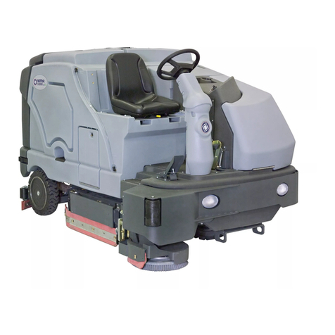
Crescent
Crescent SC8000 Operating instructions

Crescent
Crescent BA611 BA 551D User manual
Crescent
Crescent SC2000 Operating instructions
Crescent
Crescent SC6000 Operating instructions
Crescent
Crescent CS7010 User manual
Crescent
Crescent SC800 User manual
Crescent
Crescent SC530 53 B GO User manual

Crescent
Crescent SC351 Operating instructions

Crescent
Crescent SC250 User manual

