Crescent CS7010 User manual

CS7010
www.crescentindustrial.co.uk
Service
Manual

Contents iiService Manual – CS7010™
Contents
03 - General Information . . . . . . . . . . . . . . . . . . . . . . . . . . . . . 11
General Machine Description . . . . . . . . . . . . . . . . . . . . . . . . . . . . . . . . 11
Service Manual Purpose and Application . . . . . . . . . . . . . . . . . . . . . . . . . .11
Revision History . . . . . . . . . . . . . . . . . . . . . . . . . . . . . . . . . . . . . . . 11
Other Reference Manuals and Information Sources . . . . . . . . . . . . . . . . . . . . 12
Nilsk-Advance Publications . . . . . . . . . . . . . . . . . . . . . . . . . . . . . . 12
Engine Manufacturers’ Technical Manuals. . . . . . . . . . . . . . . . . . . . . . .12
Conventions . . . . . . . . . . . . . . . . . . . . . . . . . . . . . . . . . . . . . . . . . 12
Parts and Service. . . . . . . . . . . . . . . . . . . . . . . . . . . . . . . . . . . . . . .12
Nameplate . . . . . . . . . . . . . . . . . . . . . . . . . . . . . . . . . . . . . . . . . . 12
Safety . . . . . . . . . . . . . . . . . . . . . . . . . . . . . . . . . . . . . . . . . . . . .13
Symbols. . . . . . . . . . . . . . . . . . . . . . . . . . . . . . . . . . . . . . . . . .13
General Safety Instructions . . . . . . . . . . . . . . . . . . . . . . . . . . . . . . 13
Hopper Prop Rod . . . . . . . . . . . . . . . . . . . . . . . . . . . . . . . . . . . . . . .15
To Engage the Hopper Prop Rod . . . . . . . . . . . . . . . . . . . . . . . . . . 15
To Disengage the Hopper Prop Rod. . . . . . . . . . . . . . . . . . . . . . . . .15
Lifting the Machine . . . . . . . . . . . . . . . . . . . . . . . . . . . . . . . . . . . . . 16
Transporting the Machine . . . . . . . . . . . . . . . . . . . . . . . . . . . . . . . . . .16
Towing the Machine . . . . . . . . . . . . . . . . . . . . . . . . . . . . . . . . . . . . . 17
Diagnostic and Service Tools . . . . . . . . . . . . . . . . . . . . . . . . . . . . . . . . 18
Technical Specications . . . . . . . . . . . . . . . . . . . . . . . . . . . . . . . . . . . 19
General Specications . . . . . . . . . . . . . . . . . . . . . . . . . . . . . . . . . .19
Overall Dimensions . . . . . . . . . . . . . . . . . . . . . . . . . . . . . . . . . . . 20
Fastener Torque Specications . . . . . . . . . . . . . . . . . . . . . . . . . . . . . 21
Maintenance . . . . . . . . . . . . . . . . . . . . . . . . . . . . . . . . . . . . . . . . . 22
Maintenance Schedule. . . . . . . . . . . . . . . . . . . . . . . . . . . . . . . . . .22
Recommended Service Materials . . . . . . . . . . . . . . . . . . . . . . . . . . . . 22
Routine Maintenance . . . . . . . . . . . . . . . . . . . . . . . . . . . . . . . . . . 22
Lubrication Points . . . . . . . . . . . . . . . . . . . . . . . . . . . . . . . . . . . . 24
EcoFlex System Maintenance . . . . . . . . . . . . . . . . . . . . . . . . . . . . . .25
To Purge When Changing Detergents (the scrub system must be off) . . . . . . 25
To Purge Weekly (the scrub system must be off). . . . . . . . . . . . . . . . . .25
PM Checklist . . . . . . . . . . . . . . . . . . . . . . . . . . . . . . . . . . . . . . . . . 26
Machine Controls. . . . . . . . . . . . . . . . . . . . . . . . . . . . . . . . . . . . . . .28
Control Panel - General Layout . . . . . . . . . . . . . . . . . . . . . . . . . . . . .28
Miscellaneous Controls . . . . . . . . . . . . . . . . . . . . . . . . . . . . . . . . . 28
Scrub Controls . . . . . . . . . . . . . . . . . . . . . . . . . . . . . . . . . . . . . . 29
Sweep Controls. . . . . . . . . . . . . . . . . . . . . . . . . . . . . . . . . . . . . .30
Hopper Controls . . . . . . . . . . . . . . . . . . . . . . . . . . . . . . . . . . . . .30
OLED Display . . . . . . . . . . . . . . . . . . . . . . . . . . . . . . . . . . . . . . . . 31
Steering Wheel . . . . . . . . . . . . . . . . . . . . . . . . . . . . . . . . . . . . . . . . 32
Foot Pedals . . . . . . . . . . . . . . . . . . . . . . . . . . . . . . . . . . . . . . . . . . 32
04 - Control System . . . . . . . . . . . . . . . . . . . . . . . . . . . . . . . . 33
Functional Description. . . . . . . . . . . . . . . . . . . . . . . . . . . . . . . . . . . .33
Functional Diagram . . . . . . . . . . . . . . . . . . . . . . . . . . . . . . . . . . . 34
Power Modules . . . . . . . . . . . . . . . . . . . . . . . . . . . . . . . . . . . . . .35
CAN Bus Communication . . . . . . . . . . . . . . . . . . . . . . . . . . . . . . . . 36
Component Locations . . . . . . . . . . . . . . . . . . . . . . . . . . . . . . . . . . . . 37
Main Machine Controller Programming . . . . . . . . . . . . . . . . . . . . . . . . . . 38
Service Mode Access . . . . . . . . . . . . . . . . . . . . . . . . . . . . . . . . . . . 38
Menu Navigation. . . . . . . . . . . . . . . . . . . . . . . . . . . . . . . . . . . . .38
Programming Menu Outline . . . . . . . . . . . . . . . . . . . . . . . . . . . . . . 39

Contents iiiService Manual – CS7010™
Hours Menu . . . . . . . . . . . . . . . . . . . . . . . . . . . . . . . . . . . . . . . 40
Faults Menu . . . . . . . . . . . . . . . . . . . . . . . . . . . . . . . . . . . . . . . 40
Service Menu. . . . . . . . . . . . . . . . . . . . . . . . . . . . . . . . . . . . . . .40
A1 Main Controller . . . . . . . . . . . . . . . . . . . . . . . . . . . . . . . . . 40
A2 and A3 Power Modules . . . . . . . . . . . . . . . . . . . . . . . . . . . . . 41
A4 Drive Controller . . . . . . . . . . . . . . . . . . . . . . . . . . . . . . . . . 41
Engine Menu. . . . . . . . . . . . . . . . . . . . . . . . . . . . . . . . . . . . .41
Output Test . . . . . . . . . . . . . . . . . . . . . . . . . . . . . . . . . . . . . 42
Panel Test . . . . . . . . . . . . . . . . . . . . . . . . . . . . . . . . . . . . . . 42
Options Menu . . . . . . . . . . . . . . . . . . . . . . . . . . . . . . . . . . . . . . 42
Conguration Menu . . . . . . . . . . . . . . . . . . . . . . . . . . . . . . . . . . . 44
System Menu. . . . . . . . . . . . . . . . . . . . . . . . . . . . . . . . . . . . . . .44
Maintenance and Adjustment . . . . . . . . . . . . . . . . . . . . . . . . . . . . . . . . 45
Firmware Update . . . . . . . . . . . . . . . . . . . . . . . . . . . . . . . . . . . . 45
Troubleshooting . . . . . . . . . . . . . . . . . . . . . . . . . . . . . . . . . . . . . . . 46
Fault Codes. . . . . . . . . . . . . . . . . . . . . . . . . . . . . . . . . . . . . . . .46
A1 Main Controller . . . . . . . . . . . . . . . . . . . . . . . . . . . . . . . . . 46
A2 Power Module #1. . . . . . . . . . . . . . . . . . . . . . . . . . . . . . . . .49
A3 Power Module #2. . . . . . . . . . . . . . . . . . . . . . . . . . . . . . . . .52
A4 Drive Controller . . . . . . . . . . . . . . . . . . . . . . . . . . . . . . . . . 55
A5 Steering Controller . . . . . . . . . . . . . . . . . . . . . . . . . . . . . . . 57
Device Output Dependencies . . . . . . . . . . . . . . . . . . . . . . . . . . . . . . 59
Removal and Installation . . . . . . . . . . . . . . . . . . . . . . . . . . . . . . . . . . 65
Main Machine Controller . . . . . . . . . . . . . . . . . . . . . . . . . . . . . . . .65
Specications—Shop Measurements . . . . . . . . . . . . . . . . . . . . . . . . . . . . 66
Main Machine Controller . . . . . . . . . . . . . . . . . . . . . . . . . . . . . . . . 66
J1 Connector . . . . . . . . . . . . . . . . . . . . . . . . . . . . . . . . . . . . 66
J2 Connector . . . . . . . . . . . . . . . . . . . . . . . . . . . . . . . . . . . .68
Power Modules . . . . . . . . . . . . . . . . . . . . . . . . . . . . . . . . . . . . . .69
A2 Power Module 1 . . . . . . . . . . . . . . . . . . . . . . . . . . . . . . . . . 69
A3 Power Module 2 . . . . . . . . . . . . . . . . . . . . . . . . . . . . . . . . . 70
10 - Chassis System . . . . . . . . . . . . . . . . . . . . . . . . . . . . . . . . 71
Functional Description. . . . . . . . . . . . . . . . . . . . . . . . . . . . . . . . . . . .71
14 - Wheel System, Non-Traction . . . . . . . . . . . . . . . . . . . . . . . . 72
Functional Description. . . . . . . . . . . . . . . . . . . . . . . . . . . . . . . . . . . .72
Maintenance and Adjustments . . . . . . . . . . . . . . . . . . . . . . . . . . . . . . . 73
Adjust the Brakes . . . . . . . . . . . . . . . . . . . . . . . . . . . . . . . . . . . . 73
Troubleshooting . . . . . . . . . . . . . . . . . . . . . . . . . . . . . . . . . . . . . . . 74
Removal and Installation . . . . . . . . . . . . . . . . . . . . . . . . . . . . . . . . . . 74
Wheel . . . . . . . . . . . . . . . . . . . . . . . . . . . . . . . . . . . . . . . . . . .74
Wheel Bearing . . . . . . . . . . . . . . . . . . . . . . . . . . . . . . . . . . . . . . 74
Brake and Spindle Assembly . . . . . . . . . . . . . . . . . . . . . . . . . . . . . . 75
20 - Wheel System, Traction . . . . . . . . . . . . . . . . . . . . . . . . . . . 76
Functional Description. . . . . . . . . . . . . . . . . . . . . . . . . . . . . . . . . . . .76
Drive Motor . . . . . . . . . . . . . . . . . . . . . . . . . . . . . . . . . . . . . . . 76
Drive Pedal Potentiometer . . . . . . . . . . . . . . . . . . . . . . . . . . . . . . . 77
Drive Controller . . . . . . . . . . . . . . . . . . . . . . . . . . . . . . . . . . . . . 77
Circuit Description. . . . . . . . . . . . . . . . . . . . . . . . . . . . . . . . . . . .78
Powering up the Drive Controller . . . . . . . . . . . . . . . . . . . . . . . . . 78
CAN Bus . . . . . . . . . . . . . . . . . . . . . . . . . . . . . . . . . . . . . . . 79
Component Locations . . . . . . . . . . . . . . . . . . . . . . . . . . . . . . . . . . . . 79
Maintenance and Adjustments . . . . . . . . . . . . . . . . . . . . . . . . . . . . . . . 80
Gear Box Oil . . . . . . . . . . . . . . . . . . . . . . . . . . . . . . . . . . . . . . . 80

Contents ivService Manual – CS7010™
Drive Pedal Neutral Position . . . . . . . . . . . . . . . . . . . . . . . . . . . . . . 80
Troubleshooting . . . . . . . . . . . . . . . . . . . . . . . . . . . . . . . . . . . . . . . 81
Fault Codes. . . . . . . . . . . . . . . . . . . . . . . . . . . . . . . . . . . . . . . .81
Removal and Installation . . . . . . . . . . . . . . . . . . . . . . . . . . . . . . . . . . 81
Drive Motor and Gearbox Assembly . . . . . . . . . . . . . . . . . . . . . . . . . .81
Drive Wheel . . . . . . . . . . . . . . . . . . . . . . . . . . . . . . . . . . . . . . . 84
Drive Controller . . . . . . . . . . . . . . . . . . . . . . . . . . . . . . . . . . . . . 84
Specications . . . . . . . . . . . . . . . . . . . . . . . . . . . . . . . . . . . . . . . . .85
Shop Measurements . . . . . . . . . . . . . . . . . . . . . . . . . . . . . . . . . . . 85
Wheel Drive K4 Contactor . . . . . . . . . . . . . . . . . . . . . . . . . . . . . 85
Drive Controller. . . . . . . . . . . . . . . . . . . . . . . . . . . . . . . . . . .85
22 - Steering System . . . . . . . . . . . . . . . . . . . . . . . . . . . . . . . . 86
Functional Description. . . . . . . . . . . . . . . . . . . . . . . . . . . . . . . . . . . .86
Steering Limit Switches . . . . . . . . . . . . . . . . . . . . . . . . . . . . . . . . .86
Steering Motor . . . . . . . . . . . . . . . . . . . . . . . . . . . . . . . . . . . . . .87
Commutator Resolver . . . . . . . . . . . . . . . . . . . . . . . . . . . . . . . . . . 88
Steering Position Sensor & TFD . . . . . . . . . . . . . . . . . . . . . . . . . . . . 89
Steering Controller . . . . . . . . . . . . . . . . . . . . . . . . . . . . . . . . . . . 89
Functional Diagram . . . . . . . . . . . . . . . . . . . . . . . . . . . . . . . . . . . 90
Component Locations . . . . . . . . . . . . . . . . . . . . . . . . . . . . . . . . . . . . 91
Troubleshooting . . . . . . . . . . . . . . . . . . . . . . . . . . . . . . . . . . . . . . . 92
Fault Codes. . . . . . . . . . . . . . . . . . . . . . . . . . . . . . . . . . . . . . . .92
Symptom Troubleshooting. . . . . . . . . . . . . . . . . . . . . . . . . . . . . . . .92
Removal and Installation . . . . . . . . . . . . . . . . . . . . . . . . . . . . . . . . . . 93
Steering Wheel Sensor and TFD . . . . . . . . . . . . . . . . . . . . . . . . . . . . 93
Steering Controller . . . . . . . . . . . . . . . . . . . . . . . . . . . . . . . . . . . 95
Steering Actuator Motor. . . . . . . . . . . . . . . . . . . . . . . . . . . . . . . . .95
Specications . . . . . . . . . . . . . . . . . . . . . . . . . . . . . . . . . . . . . . . . .96
Shop Measurements . . . . . . . . . . . . . . . . . . . . . . . . . . . . . . . . . . . 96
24 - Electrical System . . . . . . . . . . . . . . . . . . . . . . . . . . . . . . . 97
Functional Description. . . . . . . . . . . . . . . . . . . . . . . . . . . . . . . . . . . .97
Overview . . . . . . . . . . . . . . . . . . . . . . . . . . . . . . . . . . . . . . . . . 97
Wiring Harnesses . . . . . . . . . . . . . . . . . . . . . . . . . . . . . . . . . . . . 97
Circuit Protection . . . . . . . . . . . . . . . . . . . . . . . . . . . . . . . . . . . . 98
Un-Switched Power . . . . . . . . . . . . . . . . . . . . . . . . . . . . . . . . . . . 98
Switched Power . . . . . . . . . . . . . . . . . . . . . . . . . . . . . . . . . . . . . 98
Prime Power Alternator (Generator) . . . . . . . . . . . . . . . . . . . . . . . . . . 98
Lighting . . . . . . . . . . . . . . . . . . . . . . . . . . . . . . . . . . . . . . . . . 98
Low Voltage Cutout . . . . . . . . . . . . . . . . . . . . . . . . . . . . . . . . . . . 98
Component Locations . . . . . . . . . . . . . . . . . . . . . . . . . . . . . . . . . . . . 99
Battery Interlock or Interlock Jumper . . . . . . . . . . . . . . . . . . . . . . . 99
Hybrid Machine Batteries. . . . . . . . . . . . . . . . . . . . . . . . . . . . . .99
Circuit Protection and Control . . . . . . . . . . . . . . . . . . . . . . . . . . 100
Electrical Panel Layout . . . . . . . . . . . . . . . . . . . . . . . . . . . . . . . . 101
Harness to Harness Connector Locations . . . . . . . . . . . . . . . . . . . . . . . . . 102
Connector Pin-Outs . . . . . . . . . . . . . . . . . . . . . . . . . . . . . . . . . . . . 104
Maintenance and Adjustments . . . . . . . . . . . . . . . . . . . . . . . . . . . . . . 115
Charging the Battery (Battery Model) . . . . . . . . . . . . . . . . . . . . . . . . 115
Generator Drive Belt . . . . . . . . . . . . . . . . . . . . . . . . . . . . . . . . . 115
Troubleshooting . . . . . . . . . . . . . . . . . . . . . . . . . . . . . . . . . . . . . . 115
Alternator-generator is not charging . . . . . . . . . . . . . . . . . . . . . . . . . 115
Insufcient machine operation time (Battery Model) . . . . . . . . . . . . . . . . 115
Insufcient machine operation time with engine off (Hybrid models). . . . . . . . 115
Removal and Installation . . . . . . . . . . . . . . . . . . . . . . . . . . . . . . . . . 116

Contents vService Manual – CS7010™
Alternator-Generator Drive Belt . . . . . . . . . . . . . . . . . . . . . . . . . . . 116
Alternator-Generator . . . . . . . . . . . . . . . . . . . . . . . . . . . . . . . . . 118
Wiring Diagrams . . . . . . . . . . . . . . . . . . . . . . . . . . . . . . . . . . . . . . 119
Working with Schematics and Diagrams . . . . . . . . . . . . . . . . . . . . . . . 119
Navigation . . . . . . . . . . . . . . . . . . . . . . . . . . . . . . . . . . . . . 119
Common Schematic Symbols . . . . . . . . . . . . . . . . . . . . . . . . . . . 120
Electrical Schematic (Ladder Diagram) . . . . . . . . . . . . . . . . . . . . . . . 121
Sheet 1, Main Controller Part 1 . . . . . . . . . . . . . . . . . . . . . . . . . 121
Sheet 2, Main Controller Part 2 . . . . . . . . . . . . . . . . . . . . . . . . . 122
Sheet 3, A2 Power Module #1 . . . . . . . . . . . . . . . . . . . . . . . . . . . 123
Sheet 4, A3 Power Module #2 . . . . . . . . . . . . . . . . . . . . . . . . . . . 124
Sheet 5, A4 Drive Controller . . . . . . . . . . . . . . . . . . . . . . . . . . . 125
Sheet 6, A5 Steering Controller. . . . . . . . . . . . . . . . . . . . . . . . . . 126
Sheet 7, Kubota Diesel Engine System . . . . . . . . . . . . . . . . . . . . . . 127
Sheet 8, Kubota Gasoline Engine System . . . . . . . . . . . . . . . . . . . . 128
Sheet 9, Kubota LEV Engine System Part 1 . . . . . . . . . . . . . . . . . . . 129
Sheet 10, Kubota LEV Engine System Part 2 . . . . . . . . . . . . . . . . . . 130
Sheet 11, Trackclean Connections . . . . . . . . . . . . . . . . . . . . . . . . 131
Wiring Harness Diagram . . . . . . . . . . . . . . . . . . . . . . . . . . . . . . . 132
Sheet 1: Main Harness 1 . . . . . . . . . . . . . . . . . . . . . . . . . . . . . 132
Sheet 2: Main Harness 2 . . . . . . . . . . . . . . . . . . . . . . . . . . . . . 133
Sheet 3: Main Harness 3 . . . . . . . . . . . . . . . . . . . . . . . . . . . . . 134
Sheet 4: Hopper Harness . . . . . . . . . . . . . . . . . . . . . . . . . . . . . 135
Sheet 5: LEV Engine Interface . . . . . . . . . . . . . . . . . . . . . . . . . . 136
Sheet 6: Glow Plug, Vacuum, Tail Light . . . . . . . . . . . . . . . . . . . . . 137
Sheet 7: Engine Battery, Generator Harness . . . . . . . . . . . . . . . . . . 138
Sheet 8: Trackclean Harness . . . . . . . . . . . . . . . . . . . . . . . . . . . 139
28 - Engine System - LPG LEV . . . . . . . . . . . . . . . . . . . . . . . . . .140
Functional Description. . . . . . . . . . . . . . . . . . . . . . . . . . . . . . . . . . . 140
Circuit Descriptions . . . . . . . . . . . . . . . . . . . . . . . . . . . . . . . . . . 141
Engine Starter Control . . . . . . . . . . . . . . . . . . . . . . . . . . . . . . 141
Engine RPM Control . . . . . . . . . . . . . . . . . . . . . . . . . . . . . . . 142
Normal Engine Shut Off. . . . . . . . . . . . . . . . . . . . . . . . . . . . . . . . 142
Engine Protection Modes . . . . . . . . . . . . . . . . . . . . . . . . . . . . . . . 142
Component Locations . . . . . . . . . . . . . . . . . . . . . . . . . . . . . . . . . . . 143
Maintenance and Adjustments . . . . . . . . . . . . . . . . . . . . . . . . . . . . . . 145
Maintenance Checklist . . . . . . . . . . . . . . . . . . . . . . . . . . . . . . . . 145
Change Engine Oil and Oil Filter . . . . . . . . . . . . . . . . . . . . . . . . . . . 145
Change Engine Coolant . . . . . . . . . . . . . . . . . . . . . . . . . . . . . . . . 145
Inspect Air Filter. . . . . . . . . . . . . . . . . . . . . . . . . . . . . . . . . . . . 146
Replace Air Filters . . . . . . . . . . . . . . . . . . . . . . . . . . . . . . . . . . . 146
Troubleshooting . . . . . . . . . . . . . . . . . . . . . . . . . . . . . . . . . . . . . . 147
Engine Management System . . . . . . . . . . . . . . . . . . . . . . . . . . . . . . . 147
Checking Spark . . . . . . . . . . . . . . . . . . . . . . . . . . . . . . . . . . . . 147
Checking LPG Primary Pressure . . . . . . . . . . . . . . . . . . . . . . . . . . . 148
Removal and Installation . . . . . . . . . . . . . . . . . . . . . . . . . . . . . . . . . 149
Engine Assembly. . . . . . . . . . . . . . . . . . . . . . . . . . . . . . . . . . . . 149
Specications . . . . . . . . . . . . . . . . . . . . . . . . . . . . . . . . . . . . . . . . 150
Fuel System . . . . . . . . . . . . . . . . . . . . . . . . . . . . . . . . . . . . . . 150
Engine Oil . . . . . . . . . . . . . . . . . . . . . . . . . . . . . . . . . . . . . . . 150
Engine Coolant. . . . . . . . . . . . . . . . . . . . . . . . . . . . . . . . . . . . . 150
Shop Measurements . . . . . . . . . . . . . . . . . . . . . . . . . . . . . . . . . . 150
Ignition System . . . . . . . . . . . . . . . . . . . . . . . . . . . . . . . . . . 150
Fuel System . . . . . . . . . . . . . . . . . . . . . . . . . . . . . . . . . . . . 151
Engine . . . . . . . . . . . . . . . . . . . . . . . . . . . . . . . . . . . . . . . 151
Special Tools . . . . . . . . . . . . . . . . . . . . . . . . . . . . . . . . . . . . . . . . 152

Contents viService Manual – CS7010™
28 - Engine System, Diesel . . . . . . . . . . . . . . . . . . . . . . . . . . . .154
Functional Description. . . . . . . . . . . . . . . . . . . . . . . . . . . . . . . . . . . 154
Engine starter control . . . . . . . . . . . . . . . . . . . . . . . . . . . . . . . . . 155
Fuel pump control . . . . . . . . . . . . . . . . . . . . . . . . . . . . . . . . . . . 155
Engine Protection . . . . . . . . . . . . . . . . . . . . . . . . . . . . . . . . . . . 156
Over Temperature Shutdown . . . . . . . . . . . . . . . . . . . . . . . . . . . 156
Low Oil Pressure Shutdown . . . . . . . . . . . . . . . . . . . . . . . . . . . 157
Engine RPM control . . . . . . . . . . . . . . . . . . . . . . . . . . . . . . . . . . 158
Glow plug control . . . . . . . . . . . . . . . . . . . . . . . . . . . . . . . . . . . 160
Component Locations . . . . . . . . . . . . . . . . . . . . . . . . . . . . . . . . . . . 161
Maintenance and Adjustments . . . . . . . . . . . . . . . . . . . . . . . . . . . . . . 164
Diesel Engine Maintenance Schedule. . . . . . . . . . . . . . . . . . . . . . . . . 164
Change Engine Oil and Oil Filter . . . . . . . . . . . . . . . . . . . . . . . . . . . 165
Change Engine Coolant . . . . . . . . . . . . . . . . . . . . . . . . . . . . . . . . 165
Replace Fuel Filter. . . . . . . . . . . . . . . . . . . . . . . . . . . . . . . . . . . 165
Bleed Fuel System . . . . . . . . . . . . . . . . . . . . . . . . . . . . . . . . . . . 166
Inspect Air Filter. . . . . . . . . . . . . . . . . . . . . . . . . . . . . . . . . . . . 166
Replace Air Filters . . . . . . . . . . . . . . . . . . . . . . . . . . . . . . . . . . . 167
Troubleshooting . . . . . . . . . . . . . . . . . . . . . . . . . . . . . . . . . . . . . . 168
No crank – The starter does not engage . . . . . . . . . . . . . . . . . . . . . . . 168
Cranks but does not start . . . . . . . . . . . . . . . . . . . . . . . . . . . . . . . 168
Cannot Achieve Either Run or Maximum Engine Speed . . . . . . . . . . . . . . 170
Compression Test . . . . . . . . . . . . . . . . . . . . . . . . . . . . . . . . . . . 171
Removal and Installation . . . . . . . . . . . . . . . . . . . . . . . . . . . . . . . . . 173
Engine RPM Sensor Installation . . . . . . . . . . . . . . . . . . . . . . . . . . . 173
Engine Assembly. . . . . . . . . . . . . . . . . . . . . . . . . . . . . . . . . . . . 173
Specications . . . . . . . . . . . . . . . . . . . . . . . . . . . . . . . . . . . . . . . . 174
Fuel Pump; . . . . . . . . . . . . . . . . . . . . . . . . . . . . . . . . . . . . . . 174
Glow Plugs . . . . . . . . . . . . . . . . . . . . . . . . . . . . . . . . . . . . . . . 174
Engine Compression . . . . . . . . . . . . . . . . . . . . . . . . . . . . . . . . . . 174
Engine Oil Capacity . . . . . . . . . . . . . . . . . . . . . . . . . . . . . . . . . . 174
Engine Oil Type . . . . . . . . . . . . . . . . . . . . . . . . . . . . . . . . . . . . 174
Engine Oil Viscosity . . . . . . . . . . . . . . . . . . . . . . . . . . . . . . . . . . 175
Cooling System. . . . . . . . . . . . . . . . . . . . . . . . . . . . . . . . . . . . . 175
Engine Coolant . . . . . . . . . . . . . . . . . . . . . . . . . . . . . . . . . . 175
Radiator Cap. . . . . . . . . . . . . . . . . . . . . . . . . . . . . . . . . . . . 175
Shop Measurements . . . . . . . . . . . . . . . . . . . . . . . . . . . . . . . . . . 175
Engine RPM Sensor . . . . . . . . . . . . . . . . . . . . . . . . . . . . . . . . 175
Actuator . . . . . . . . . . . . . . . . . . . . . . . . . . . . . . . . . . . . . . 175
Engine Compression. . . . . . . . . . . . . . . . . . . . . . . . . . . . . . . .176
Fuel System Return Fuel Flow . . . . . . . . . . . . . . . . . . . . . . . . . . 176
Starter . . . . . . . . . . . . . . . . . . . . . . . . . . . . . . . . . . . . . . . 176
Glow Plug Relay . . . . . . . . . . . . . . . . . . . . . . . . . . . . . . . . . 176
Special Tools . . . . . . . . . . . . . . . . . . . . . . . . . . . . . . . . . . . . . . . . 177
28 - Engine System - Petrol (Gasoline) . . . . . . . . . . . . . . . . . . . . . 178
Functional Description. . . . . . . . . . . . . . . . . . . . . . . . . . . . . . . . . . . 178
Kubota WG972-GL-E3-NFK-1 Petrol (Gasoline) . . . . . . . . . . . . . . . . . . . 178
Circuit Descriptions . . . . . . . . . . . . . . . . . . . . . . . . . . . . . . . . . . 179
Ignition System . . . . . . . . . . . . . . . . . . . . . . . . . . . . . . . . . . 179
Engine Starter and Carburetor Choke Control . . . . . . . . . . . . . . . . . 181
Throttle Control Modes . . . . . . . . . . . . . . . . . . . . . . . . . . . . . . . . 182
Ignition Off. . . . . . . . . . . . . . . . . . . . . . . . . . . . . . . . . . . . . 182
Ignition On. . . . . . . . . . . . . . . . . . . . . . . . . . . . . . . . . . . . . 183
Cranking . . . . . . . . . . . . . . . . . . . . . . . . . . . . . . . . . . . . . . 184
Normal Running . . . . . . . . . . . . . . . . . . . . . . . . . . . . . . . . . . 185
Engine RPM Control . . . . . . . . . . . . . . . . . . . . . . . . . . . . . . . 185

Contents viiService Manual – CS7010™
Normal Engine Shut Off. . . . . . . . . . . . . . . . . . . . . . . . . . . . . . . . 186
Engine Overheat Shutdown. . . . . . . . . . . . . . . . . . . . . . . . . . . . 187
Lost Oil Pressure Shutdown . . . . . . . . . . . . . . . . . . . . . . . . . . . 188
Component Locations . . . . . . . . . . . . . . . . . . . . . . . . . . . . . . . . . . . 189
Engine Right Side View (Toward front of machine) . . . . . . . . . . . . . . . . . 190
Engine Back Side View (Toward right of machine) . . . . . . . . . . . . . . . . . 191
Engine Left Side View (Toward back of machine) . . . . . . . . . . . . . . . . . 191
Fuel Tank Area . . . . . . . . . . . . . . . . . . . . . . . . . . . . . . . . . . . . 192
Maintenance and Adjustments . . . . . . . . . . . . . . . . . . . . . . . . . . . . . . 193
Maintenance Checklist . . . . . . . . . . . . . . . . . . . . . . . . . . . . . . . . 193
Change Engine Oil and Oil Filter . . . . . . . . . . . . . . . . . . . . . . . . . . . 194
Change Engine Coolant . . . . . . . . . . . . . . . . . . . . . . . . . . . . . . . . 194
Inspect Air Filter. . . . . . . . . . . . . . . . . . . . . . . . . . . . . . . . . . . . 195
Replace Air Filters . . . . . . . . . . . . . . . . . . . . . . . . . . . . . . . . . . . 195
Troubleshooting . . . . . . . . . . . . . . . . . . . . . . . . . . . . . . . . . . . . . . 196
Checking Spark . . . . . . . . . . . . . . . . . . . . . . . . . . . . . . . . . . . . 196
No crank - The starter does not engage. . . . . . . . . . . . . . . . . . . . . . . . 196
Cranks but does not start – No Spark . . . . . . . . . . . . . . . . . . . . . . . . 197
Cranks but does not start (has sufcient spark) . . . . . . . . . . . . . . . . . . . 197
Achieves one but not ALL RPM modes.. . . . . . . . . . . . . . . . . . . . . . . .198
Removal and Installation . . . . . . . . . . . . . . . . . . . . . . . . . . . . . . . . . 199
Engine RPM Sensor Installation . . . . . . . . . . . . . . . . . . . . . . . . . . . 199
Engine Assembly. . . . . . . . . . . . . . . . . . . . . . . . . . . . . . . . . . . . 199
Specications . . . . . . . . . . . . . . . . . . . . . . . . . . . . . . . . . . . . . . . . 200
Engine Oil . . . . . . . . . . . . . . . . . . . . . . . . . . . . . . . . . . . . . . . 200
Engine Coolant. . . . . . . . . . . . . . . . . . . . . . . . . . . . . . . . . . . . . 200
Shop Measurements . . . . . . . . . . . . . . . . . . . . . . . . . . . . . . . . . . 200
Ignition System . . . . . . . . . . . . . . . . . . . . . . . . . . . . . . . . . . 200
Spark Controller Measurements: . . . . . . . . . . . . . . . . . . . . . . . . . 201
Governor Control System . . . . . . . . . . . . . . . . . . . . . . . . . . . . . 201
Woodward L Series Actuator Measurements . . . . . . . . . . . . . . . . . . 201
Fuel System . . . . . . . . . . . . . . . . . . . . . . . . . . . . . . . . . . . . 202
Engine . . . . . . . . . . . . . . . . . . . . . . . . . . . . . . . . . . . . . . . 202
30 - Solution System . . . . . . . . . . . . . . . . . . . . . . . . . . . . . . . .203
Functional Description. . . . . . . . . . . . . . . . . . . . . . . . . . . . . . . . . . . 203
Overview . . . . . . . . . . . . . . . . . . . . . . . . . . . . . . . . . . . . . . . . 203
Solution Flow Control - Non-EcoFlex™ Machines . . . . . . . . . . . . . . . . . . 203
Solution Flow Control - EcoFlex™ Machines . . . . . . . . . . . . . . . . . . . . .203
EcoFlex™ Detergent System . . . . . . . . . . . . . . . . . . . . . . . . . . . . . 204
Extended Scrub System . . . . . . . . . . . . . . . . . . . . . . . . . . . . . . . . 204
Optional Hot Water System (LP and Diesel EcoFlex™ Machines Only) . . . . . . 204
Optional Wash Hose Kit . . . . . . . . . . . . . . . . . . . . . . . . . . . . . . . . 204
Optional High-pressure Spray System (LP and Diesel Only) . . . . . . . . . . . . 205
Solution Level Sensor . . . . . . . . . . . . . . . . . . . . . . . . . . . . . . . . . 205
Solution System Wiring Diagram . . . . . . . . . . . . . . . . . . . . . . . . . . . 206
Circuit Description. . . . . . . . . . . . . . . . . . . . . . . . . . . . . . . . . . . 206
Component Locations . . . . . . . . . . . . . . . . . . . . . . . . . . . . . . . . . . . 208
Solution Tank . . . . . . . . . . . . . . . . . . . . . . . . . . . . . . . . . . . . . 208
Drain Hose . . . . . . . . . . . . . . . . . . . . . . . . . . . . . . . . . . . . . 208
Solution Filter and Solution Shutoff Valve. . . . . . . . . . . . . . . . . . . . 208
Solution Pressure Sensor . . . . . . . . . . . . . . . . . . . . . . . . . . . . . 209
Solution Pump (EcoFlex™ Models Only) . . . . . . . . . . . . . . . . . . . . . . . 209
Low Pressure (Wash Hose) Pump . . . . . . . . . . . . . . . . . . . . . . . . . . 209
Solution Solenoid Valve . . . . . . . . . . . . . . . . . . . . . . . . . . . . . . . . 210
Solution Nozzles . . . . . . . . . . . . . . . . . . . . . . . . . . . . . . . . . . . . 210
EcoFlex™ Detergent Bottles and Pumps . . . . . . . . . . . . . . . . . . . . . . . 211

Contents viiiService Manual – CS7010™
High-pressure Spray System Pump. . . . . . . . . . . . . . . . . . . . . . . . . .211
Extended Scrub System . . . . . . . . . . . . . . . . . . . . . . . . . . . . . . . . 212
Maintenance and Adjustments . . . . . . . . . . . . . . . . . . . . . . . . . . . . . . 213
To Clean the Solution Filter Screen. . . . . . . . . . . . . . . . . . . . . . . . . . 213
To Clean the Extended Scrub System Strainer . . . . . . . . . . . . . . . . . . . 214
To Clean the High Pressure Solution Filter . . . . . . . . . . . . . . . . . . . . . 214
To Adjust the Belt Tension on the High Pressure Pump. . . . . . . . . . . . . . . 215
Troubleshooting . . . . . . . . . . . . . . . . . . . . . . . . . . . . . . . . . . . . . . 216
Removal and Installation . . . . . . . . . . . . . . . . . . . . . . . . . . . . . . . . . 218
Solution Tank . . . . . . . . . . . . . . . . . . . . . . . . . . . . . . . . . . . . . 218
Solution Shutoff Valve . . . . . . . . . . . . . . . . . . . . . . . . . . . . . . . . . 222
Solution Filter Assembly . . . . . . . . . . . . . . . . . . . . . . . . . . . . . . . 222
Solution Solenoid Valve . . . . . . . . . . . . . . . . . . . . . . . . . . . . . . . . 223
Detergent Pump (EcoFlex™ Models Only) . . . . . . . . . . . . . . . . . . . . . . 224
Specications . . . . . . . . . . . . . . . . . . . . . . . . . . . . . . . . . . . . . . . . 225
Special Tools . . . . . . . . . . . . . . . . . . . . . . . . . . . . . . . . . . . . . . . . 225
34 - Scrub System . . . . . . . . . . . . . . . . . . . . . . . . . . . . . . . . . 226
Functional Description. . . . . . . . . . . . . . . . . . . . . . . . . . . . . . . . . . . 226
Overview . . . . . . . . . . . . . . . . . . . . . . . . . . . . . . . . . . . . . . . . 226
Scrub System Wiring Diagram . . . . . . . . . . . . . . . . . . . . . . . . . . . . 226
Circuit Description. . . . . . . . . . . . . . . . . . . . . . . . . . . . . . . . . . . 227
Scrub Deck Actuator Motor . . . . . . . . . . . . . . . . . . . . . . . . . . . . 227
Component Locations . . . . . . . . . . . . . . . . . . . . . . . . . . . . . . . . . . . 227
Scrub Motor Assemblies . . . . . . . . . . . . . . . . . . . . . . . . . . . . . . . . 227
Right Swingarm . . . . . . . . . . . . . . . . . . . . . . . . . . . . . . . . . . . . 227
Side Squeegee Assemblies . . . . . . . . . . . . . . . . . . . . . . . . . . . . . . . 228
Scrub Deck Actuator . . . . . . . . . . . . . . . . . . . . . . . . . . . . . . . . . . 228
Maintenance and Adjustments . . . . . . . . . . . . . . . . . . . . . . . . . . . . . . 229
Replace a Leading Deck Blade . . . . . . . . . . . . . . . . . . . . . . . . . . . . 229
Replace a Trailing Deck Blade . . . . . . . . . . . . . . . . . . . . . . . . . . . . 229
Removal and Installation . . . . . . . . . . . . . . . . . . . . . . . . . . . . . . . . . 230
Side Squeegee Assembly. . . . . . . . . . . . . . . . . . . . . . . . . . . . . . . . 230
Scrub Deck Actuator . . . . . . . . . . . . . . . . . . . . . . . . . . . . . . . . . . 231
Actuator Adjustment . . . . . . . . . . . . . . . . . . . . . . . . . . . . . . . 231
Scrub Deck . . . . . . . . . . . . . . . . . . . . . . . . . . . . . . . . . . . . . . . 232
Scrub Motor . . . . . . . . . . . . . . . . . . . . . . . . . . . . . . . . . . . . . . 234
Scrub Motor Carbon Brushes . . . . . . . . . . . . . . . . . . . . . . . . . . . . . 235
Specications . . . . . . . . . . . . . . . . . . . . . . . . . . . . . . . . . . . . . . . . 239
Special Tools . . . . . . . . . . . . . . . . . . . . . . . . . . . . . . . . . . . . . . . . 239
38 - Squeegee System . . . . . . . . . . . . . . . . . . . . . . . . . . . . . . . 240
Functional Description. . . . . . . . . . . . . . . . . . . . . . . . . . . . . . . . . . . 240
Overview . . . . . . . . . . . . . . . . . . . . . . . . . . . . . . . . . . . . . . . . 240
Squeegee and Recovery Wiring Diagram . . . . . . . . . . . . . . . . . . . . . . . 240
Component Locations . . . . . . . . . . . . . . . . . . . . . . . . . . . . . . . . . . . 241
Maintenance and Adjustments . . . . . . . . . . . . . . . . . . . . . . . . . . . . . . 242
Changing Squeegee Blades . . . . . . . . . . . . . . . . . . . . . . . . . . . . . . 242
Squeegee End Wheels . . . . . . . . . . . . . . . . . . . . . . . . . . . . . . . . . 243
Squeegee Caster Wheel Bearings . . . . . . . . . . . . . . . . . . . . . . . . . . . 243
Squeegee Tilt Adjustment . . . . . . . . . . . . . . . . . . . . . . . . . . . . . . . 244
Squeegee Casters Adjustment. . . . . . . . . . . . . . . . . . . . . . . . . . . . . 245
Troubleshooting . . . . . . . . . . . . . . . . . . . . . . . . . . . . . . . . . . . . . . 245
Removal and Installation . . . . . . . . . . . . . . . . . . . . . . . . . . . . . . . . . 246
Squeegee Lift Actuator . . . . . . . . . . . . . . . . . . . . . . . . . . . . . . . . 246
Actuator Adjustment . . . . . . . . . . . . . . . . . . . . . . . . . . . . . . . 246

Contents ixService Manual – CS7010™
Squeegee Support Assembly. . . . . . . . . . . . . . . . . . . . . . . . . . . . . . 247
Squeegee Lift Arm . . . . . . . . . . . . . . . . . . . . . . . . . . . . . . . . . . . 247
Specications . . . . . . . . . . . . . . . . . . . . . . . . . . . . . . . . . . . . . . . . 248
Special Tools . . . . . . . . . . . . . . . . . . . . . . . . . . . . . . . . . . . . . . . . 248
40 - Recovery System . . . . . . . . . . . . . . . . . . . . . . . . . . . . . . . 249
Functional Description . . . . . . . . . . . . . . . . . . . . . . . . . . . . . . . . . . 249
Overview . . . . . . . . . . . . . . . . . . . . . . . . . . . . . . . . . . . . . . . . 249
Recovery and Squeegee Wiring Diagram . . . . . . . . . . . . . . . . . . . . . . . 249
Component Locations . . . . . . . . . . . . . . . . . . . . . . . . . . . . . . . . . . . 250
Recovery Tank . . . . . . . . . . . . . . . . . . . . . . . . . . . . . . . . . . . . . 250
Recovery Tank Cover and Debris Basket . . . . . . . . . . . . . . . . . . . . . . . 250
Vacuum Fan Cover Assembly . . . . . . . . . . . . . . . . . . . . . . . . . . . . . 251
Vacuum Motors . . . . . . . . . . . . . . . . . . . . . . . . . . . . . . . . . . . . 251
Float Cage and Ball Assemblies. . . . . . . . . . . . . . . . . . . . . . . . . . . .251
Maintenance and Adjustments . . . . . . . . . . . . . . . . . . . . . . . . . . . . . . 252
Clean the Vacuum Filter and Filter Screen . . . . . . . . . . . . . . . . . . . . . 252
Clean the Debris Basket. . . . . . . . . . . . . . . . . . . . . . . . . . . . . . . . 253
Troubleshooting . . . . . . . . . . . . . . . . . . . . . . . . . . . . . . . . . . . . . . 253
Removal and Installation . . . . . . . . . . . . . . . . . . . . . . . . . . . . . . . . . 254
Recovery Tank . . . . . . . . . . . . . . . . . . . . . . . . . . . . . . . . . . . . . 254
Vacuum Motor . . . . . . . . . . . . . . . . . . . . . . . . . . . . . . . . . . . . . 256
Specications . . . . . . . . . . . . . . . . . . . . . . . . . . . . . . . . . . . . . . . . 257
Special Tools . . . . . . . . . . . . . . . . . . . . . . . . . . . . . . . . . . . . . . . . 257
42 - Sweep System, Main . . . . . . . . . . . . . . . . . . . . . . . . . . . . . 258
Functional Description. . . . . . . . . . . . . . . . . . . . . . . . . . . . . . . . . . . 258
Overview . . . . . . . . . . . . . . . . . . . . . . . . . . . . . . . . . . . . . . . . 258
Sweep System Wiring Diagram . . . . . . . . . . . . . . . . . . . . . . . . . . . . 259
Circuit Description. . . . . . . . . . . . . . . . . . . . . . . . . . . . . . . . . . . 260
Main Broom Actuator . . . . . . . . . . . . . . . . . . . . . . . . . . . . . . . 260
Main Broom Motor . . . . . . . . . . . . . . . . . . . . . . . . . . . . . . . . 260
Component Locations . . . . . . . . . . . . . . . . . . . . . . . . . . . . . . . . . . . 260
Main Broom and Drive Components . . . . . . . . . . . . . . . . . . . . . . . . . 260
Maintenance and Adjustments . . . . . . . . . . . . . . . . . . . . . . . . . . . . . . 261
Adjust the Main Broom Height . . . . . . . . . . . . . . . . . . . . . . . . . . . . 261
Adjust the Main Broom Tilt . . . . . . . . . . . . . . . . . . . . . . . . . . . . . . 262
Removal and Installation . . . . . . . . . . . . . . . . . . . . . . . . . . . . . . . . . 263
Main Broom . . . . . . . . . . . . . . . . . . . . . . . . . . . . . . . . . . . . . . 263
Broom Motor . . . . . . . . . . . . . . . . . . . . . . . . . . . . . . . . . . . . . . 265
Main Broom Motor Carbon Brushes . . . . . . . . . . . . . . . . . . . . . . . . . 266
Broom Lift Actuator . . . . . . . . . . . . . . . . . . . . . . . . . . . . . . . . . . 269
Specications . . . . . . . . . . . . . . . . . . . . . . . . . . . . . . . . . . . . . . . . 270
48 - Sweep System, Side Broom . . . . . . . . . . . . . . . . . . . . . . . . . 271
Functional Description . . . . . . . . . . . . . . . . . . . . . . . . . . . . . . . . . . 271
Overview . . . . . . . . . . . . . . . . . . . . . . . . . . . . . . . . . . . . . . . . 271
Side Broom and Main Broom Wiring Diagram . . . . . . . . . . . . . . . . . . . . 272
Component Locations . . . . . . . . . . . . . . . . . . . . . . . . . . . . . . . . . . . 273
Side Brooms . . . . . . . . . . . . . . . . . . . . . . . . . . . . . . . . . . . . . . 273
Side Broom Motors. . . . . . . . . . . . . . . . . . . . . . . . . . . . . . . . . . . 273
Side Broom Actuator. . . . . . . . . . . . . . . . . . . . . . . . . . . . . . . . . . 273
Maintenance and Adjustments . . . . . . . . . . . . . . . . . . . . . . . . . . . . . . 274
Replacing a Side Broom . . . . . . . . . . . . . . . . . . . . . . . . . . . . . . . . 274
Side Broom Motor Carbon Brushes . . . . . . . . . . . . . . . . . . . . . . . . . . . . 275
Removal and Installation . . . . . . . . . . . . . . . . . . . . . . . . . . . . . . . . . 277

Contents xService Manual – CS7010™
Side Broom Motor . . . . . . . . . . . . . . . . . . . . . . . . . . . . . . . . . . . 277
Side Broom Hub . . . . . . . . . . . . . . . . . . . . . . . . . . . . . . . . . . . . 278
Side Broom Actuator. . . . . . . . . . . . . . . . . . . . . . . . . . . . . . . . . . 279
Specications . . . . . . . . . . . . . . . . . . . . . . . . . . . . . . . . . . . . . . . . 281
Special Tools . . . . . . . . . . . . . . . . . . . . . . . . . . . . . . . . . . . . . . . . 281
50 - Dust Control/DustGuard™ Systems . . . . . . . . . . . . . . . . . . . . 282
Functional Description . . . . . . . . . . . . . . . . . . . . . . . . . . . . . . . . . . 282
Overview . . . . . . . . . . . . . . . . . . . . . . . . . . . . . . . . . . . . . . . . 282
Dust Control System . . . . . . . . . . . . . . . . . . . . . . . . . . . . . . . 282
DustGuard Spray System (optional) . . . . . . . . . . . . . . . . . . . . . . . 283
Dust Control and Hopper Wiring Diagram . . . . . . . . . . . . . . . . . . . . . . 284
Component Locations . . . . . . . . . . . . . . . . . . . . . . . . . . . . . . . . . . . 285
Impeller and Filter System . . . . . . . . . . . . . . . . . . . . . . . . . . . . 285
Dust Control Filter Switch . . . . . . . . . . . . . . . . . . . . . . . . . . . . 286
DustGuard Spray System . . . . . . . . . . . . . . . . . . . . . . . . . . . . . 287
Maintenance and Adjustments . . . . . . . . . . . . . . . . . . . . . . . . . . . . . . 288
Clean the Dust Control Filter . . . . . . . . . . . . . . . . . . . . . . . . . . . . . 288
Clean the DustGuard Strainer Screen . . . . . . . . . . . . . . . . . . . . . . . . 289
Clean the DustGuard Spray Nozzles . . . . . . . . . . . . . . . . . . . . . . . . . 289
Adjust the DustGuard Spray Nozzles. . . . . . . . . . . . . . . . . . . . . . . . . 290
Troubleshooting . . . . . . . . . . . . . . . . . . . . . . . . . . . . . . . . . . . . . . 290
Removal and Installation . . . . . . . . . . . . . . . . . . . . . . . . . . . . . . . . . 291
DustGuard Solenoid Valve . . . . . . . . . . . . . . . . . . . . . . . . . . . . . . 291
Dust Control Filter Switch . . . . . . . . . . . . . . . . . . . . . . . . . . . . . . 291
DustGuard Pump . . . . . . . . . . . . . . . . . . . . . . . . . . . . . . . . . . . 292
Impeller Assembly . . . . . . . . . . . . . . . . . . . . . . . . . . . . . . . . . . . 293
Specications . . . . . . . . . . . . . . . . . . . . . . . . . . . . . . . . . . . . . . . . 294
52 - Hopper System . . . . . . . . . . . . . . . . . . . . . . . . . . . . . . . . 295
Functional Description . . . . . . . . . . . . . . . . . . . . . . . . . . . . . . . . . . 295
Overview . . . . . . . . . . . . . . . . . . . . . . . . . . . . . . . . . . . . . . . . 295
Hopper and Dust Control Wiring Diagram . . . . . . . . . . . . . . . . . . . . . . 296
Component Locations . . . . . . . . . . . . . . . . . . . . . . . . . . . . . . . . . . . 297
Upper and Lower Hopper . . . . . . . . . . . . . . . . . . . . . . . . . . . . . . . 297
Hydraulic Power Pack Assembly . . . . . . . . . . . . . . . . . . . . . . . . . . . 297
Hopper Dump Door . . . . . . . . . . . . . . . . . . . . . . . . . . . . . . . . . . 298
Hopper Dump Door Actuator . . . . . . . . . . . . . . . . . . . . . . . . . . . . . 298
Dump Door Limit Switch . . . . . . . . . . . . . . . . . . . . . . . . . . . . . . . 298
Hopper Interlock Switch. . . . . . . . . . . . . . . . . . . . . . . . . . . . . . . . 299
Hopper Prop Rod and Pull Rod . . . . . . . . . . . . . . . . . . . . . . . . . . . . 299
Maintenance and Adjustment . . . . . . . . . . . . . . . . . . . . . . . . . . . . . . . 300
Hydraulic Oil Change/Flush. . . . . . . . . . . . . . . . . . . . . . . . . . . . . . 300
Dump Door Actuator Adjustment . . . . . . . . . . . . . . . . . . . . . . . . . . . 308
Removal and Installation . . . . . . . . . . . . . . . . . . . . . . . . . . . . . . . . . 310
Hydraulic Power Pack Assembly . . . . . . . . . . . . . . . . . . . . . . . . . . . 310
LPG and Diesel Models . . . . . . . . . . . . . . . . . . . . . . . . . . . . . . 310
Battery Models. . . . . . . . . . . . . . . . . . . . . . . . . . . . . . . . . . . 312
Hopper Lift Cylinder. . . . . . . . . . . . . . . . . . . . . . . . . . . . . . . . . . 314
Hopper Interlock Switch. . . . . . . . . . . . . . . . . . . . . . . . . . . . . . . . 317
Hopper Dump Door Actuator . . . . . . . . . . . . . . . . . . . . . . . . . . . . . 318
Specications . . . . . . . . . . . . . . . . . . . . . . . . . . . . . . . . . . . . . . . . 319
90 - Options and Accessories . . . . . . . . . . . . . . . . . . . . . . . . . . .320

11Service Manual – CS7010™
03 - General Information
General Machine Description
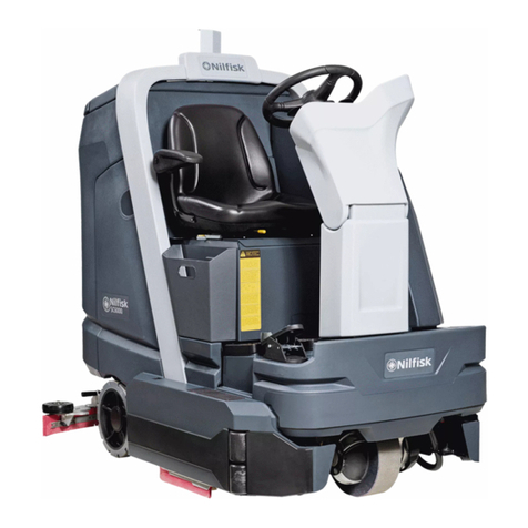
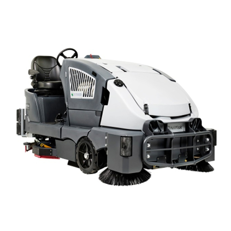
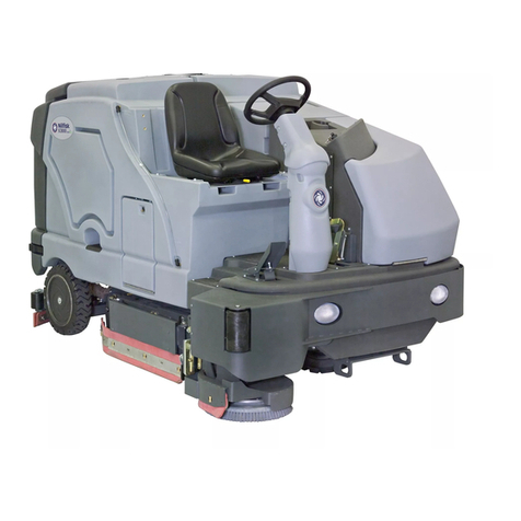
The CS7010 machines are industrial automatic rider sweeper/scrubbers with multiple sweep/scrub single-
pass coverage. Both battery (all electric) and hybrid (engine) models are available with or without the
EcoFlex™and DustGuard™ options. The scrub system uses three disc scrub brushes with variable scrub
pressure and solution ow rates. The sweep system has a center main broom and left- and right-hand side
brooms.
The fuel cell powered model is similar to the battery model in construction, except it is designed to
accommodate an approved fuel cell provided by Plug Power.
Service Manual Purpose and Application
This Service Manual a technical resource designed to aid service personnel in maintaining and repairing the
CS7010 Sweeper/Scrubber to ensure optimum performance and long service life. Please read it thoroughly
before servicing your machine.
Revision History
Revision Summary of Changes
5/2017 First Release
7/2017 • Updated electrical schematic to Rev B.
• Added main broom motor carbon brush replacement procedure
11/2017 • Addedrmwareupdateprocedure
• CorrectedKGSTpassword
• Updated Drive and Steering error codes
• Notedsteeringshaftsetscrewpositioning

12Service Manual – CS7010™ 03 - General Information
Other Reference Manuals and Information Sources
Nilsk-Advance Publications
Model Name Instructions for Use Form Number Parts List
Advance CS7010 56091206: English, Spanish, French
56042665
NilskCS7010
56042666
These manuals can be found on the following Nilsk-Advance’s electronic supported databases:
• Nilsk-Advance Dealer Customer Zone
• Nilsk-Advance website: www.Nilsk-Advance-us.com
• EzParts service/parts CD-ROM
Engine Manufacturers’ Technical Manuals
Engine Model Publication Title
Diesel: D1305-E3B-KEA-1 KubotaWSMWorkshopManual,DieselEngine,05-E3BSeries,05-E3BGSeries
LPG: WG972-GL-E3-NFK-1
KubotaWSMWorkshopManual,Gasoline,LPGEngine,WG752-G-E3,WG752-
GL-E3, WG972-G-E3, WG972-GL-E3
LPG WG972-E4 (LEV): Kubota WorkshopManual–Gasoline,LPG,NGEngineWG972-E4(EFI)
Kubota Diagnostic Manual ECU System WG972-E4” Code No.9Y110-03110
Conventions
All references to right, left, front and rear in this manual are as seen from the Operator’s seat position.
Parts and Service
Repairs should be performed by an Authorized Nilsk-Advance Service Center that employs factory-trained
service personnel and maintains an inventory of Nilsk-Advance original replacement parts and accessories.
Call the Nilsk-Advance Dealer named below for repair parts or service. Please specify the Model Number
(same as the Part Number) and Serial Number when discussing your machine.
(Dealer, afx service sticker here.)
Note: On Fuel Cell models, all issues related to the fuel cell must be referred to Plug Power, not
Nilsk-Advance.
Nameplate
The Part (Model) Number and Serial Number of your machine
are shown on the Nameplate located on the top of the machine
frame, at the left rear side of the machine underneath the
recovery tank. To access the Nameplate, tip the recovery tank
out away from the machine. This information is needed when
ordering repair parts for the machine.
Name
Plate

13Service Manual – CS7010™ 03 - General Information
Safety
Symbols
It is important for you to read and understand this manual. The information it contains relates to protecting
your safety and preventing problems. The symbols below are used to help you recognize this information.
DANGER: Indicates a potentially hazardous situation which, if not avoided, will result in death or
serious injury.
WARNING: Indicates a potentially hazardous situation which, if not avoided, could result in death
or serious injury.
CAUTION: Indicates a potentially hazardous situation which, if not avoided, could result in minor
or moderate injury.
Note: Indicates an important informational message.
General Safety Instructions
These safety instructions are included to warn you of potential bodily injury or property damage.
DANGER: Engine-powered machines emit exhaust gasses, including carbon monoxide, which
can cause serious injury or death. Always provide adequate ventilation when using
the machine.
CAUTION: Read and understand all safety warnings and instructions. Failure to follow the
warnings and instructions may result in electric shock, re, and/or serious injury.
−To avoid personal injury, this machine should be used only by properly trained and
authorized persons. This machine is not intended for use by persons with reduced
physical, sensory, or mental capabilities.
−To avoid pinching or crushing hazard, stay clear of the rear drive wheel when the
machine is initializing or running. When the machine is initialized, the steering system
will turn the wheel to the side to identify home and limit positions of the wheel steering.
−Do not operate the machine near toxic, dangerous, ammable and/or explosive
materials. This machine is not suitable for collecting dangerous or hazardous materials.
−In case of re, use a powder re extinguisher, not a water-based extinguisher.
−Do not use on surfaces having a gradient exceeding that marked on the machine. While
on ramps or inclines, avoid sudden stops when loaded. Avoid abrupt sharp turns.
−Do not use the machine without a falling object protective structure in areas where it is
likely that the operator may be struck by falling objects.
−Disconnect the power source and/or batteries before servicing electrical components.
Turn the key switch off before changing brushes or opening access panels.
−Never work under a machine without safety blocks or stands to support the machine.
−Do not dispense ammable cleaning agents, operate the machine on or near these
agents, or operate in areas where ammable liquids exist.
−When using oor cleaning detergents, follow all safety and handling instructions of the

14Service Manual – CS7010™ 03 - General Information
respective manufacturer.
−Battery charging may produce highly explosive hydrogen gas. Charge the batteries
only in well-ventilated areas and away from ignition sources or open ames.
−Safe operation of this machine requires the operator to ensure others within close
proximity are not endangered or the machine is not left operational and unattended
allowing unauthorized use.
−To avoid hydraulic oil injection or injury, always wear appropriate clothing and eye
protection when working with or near any hydraulic system.
−Take precautions to prevent hair, jewelry, or loose clothing from becoming caught in
moving parts.
Property Damage Messages
−Storage and operation temperature must be above 0°C and a humidity between 30%
and 95%, non-condensing.
−Before use, all doors and hoods should be properly latched.
−This machine is not approved for use on public paths or roads.
−This machine is only approved for hard surface use.
−Use brushes and pads supplied with the machine or those specied in the User
Manual. Using other brushes or pads could reduce safety.
−Do not wash the machine with direct or pressurised water jets, or with corrosive
substances.
−Do not allow the brush/pad to operate while the machine is stationary to avoid
damaging the oor.
−The machine must be inspected by a qualied person on a regular basis, in particular
to the engine and fuel systems on engine-powered machines, to ensure proper
operation and compliance with local or national regulations.
−If the engine misres or runs rough, stop the engine and have the machine serviced by
a qualied technician. Continued operation under this condition may result in damage
to the engine, catalytic converter, or other machine components.
−Use only factory authorized parts and accessories.
−This machine must be properly disposed of in accordance with local laws and
regulations.

15Service Manual – CS7010™ 03 - General Information
Hopper Prop Rod
CAUTION: Never work underneath the raised hopper without the hopper prop rod engaged.
To Engage the Hopper Prop Rod
1. Press and hold the hopper raise button to raise the
hopper all the way up.
2. Pull the pull rod to pivot the bottom of the hopper prop
rod toward the hopper lift cylinder until it contacts the
hopper lift cylinder.
3. Press and hold the hopper lower button to lower the
hopper until the hopper prop rod contacts the top of the
hopper lift cylinder.
To Disengage the Hopper Prop Rod
1. Press and hold the hopper raise button to raise the
hopper slightly so the hopper prop rod lifts off of the
hopper lift cylinder.
2. Push the pull rod to pivot the bottom of the hopper prop
rod away from the hopper lift cylinder.
3. Press and hold the hopper lower button to lower the
hopper.
Hopper
Prop
Rod
Hopper
Lift
Cylinder
Pull
Rod

16Service Manual – CS7010™ 03 - General Information
Lifting the Machine
CAUTION: Never work under a machine without safety stands or blocks to support the machine.
When lifting the machine, do so at the designated Tie Down/Support Locations.
Transporting the Machine
CAUTION: Before transporting the machine on an open truck or trailer, make sure the machine
is tied down securely and all access doors and covers are secured (tape and strap as
needed).
The lifting and tie-down locations are identied with a graphic molded
into the exterior body panels.
The jacking and tie-down locations are in front of the front wheels, and at the rear of the machine below the
solution tank.
Rear Support/Tie-down LocationFront Support/Tie-down Location
Jacking/
Tie-down
Location

17Service Manual – CS7010™ 03 - General Information
Towing the Machine
CAUTION: If the machine must be towed, move the machine for short distances only and do not
move the machine faster than a normal walking pace (2-3 mph, 3-5 kph).
−Tow the machine backward from one of the rear frame tie-down locations as shown
below. Do not push the machine due to the possibility of damage to the solution and
recovery tanks.
−Do not tow the machine by the squeegee tool.
• On machines not equipped with a squeegee
guard kit, tow the machine by one of the two
Tie-down Slots on the chassis (shown in green).
• On machines equipped with a squeegee guard
kit, tow the machine by the two Tie-down Slots
on the squeegee guard (shown in red).
Tie-down
Slot (2)
Tie-down
Slot (2)

18Service Manual – CS7010™ 03 - General Information
Diagnostic and Service Tools
In addition to a full set of metric and standard tools, the following items are required in order to successfully
and quickly perform troubleshooting and repair of Nilsk Industrial oor cleaning equipment.
• Laptop computer loaded with current version of EzParts, Adobe Reader and (preferably cellular) internet
access
• Digital volt ohmmeter (DVOM) with DC current clamp
• Hydrometer
• Battery load tester for checking 36V and 12V batteries.
• Automotive fuel pressure test gauge
• Static control wrist strap
• Set of torque wrenches
• Hard (printed) copies of service manuals for regularly serviced machines (available at www.advance-us.
com and other Nilsk websites).
These tools are also available from Nilsk, Inc.:
• Vacuum water lift gauge, p/n 56205281

19Service Manual – CS7010™ 03 - General Information
Technical Specications
General Specications
Model CS7010 48G CS7010 48LP CS7010 48LP
LEV CS7010 48D CS7010 48B
Battery
Part Numbers 56511001 56509000
56509006 56511540
56511541 56509001
56509007 56511713
56511811
Main Battery 36V, 770 Ah,
C6
Protection Grade IPX4 IPX4 IPX4 IPX4 IPX4
Sound Pressure Level at
operatorear(ISO11201)
82dB LpA,
3dB u(LW) 82dB LpA,
3dB u(LW) 82dB LpA,
3dB u(LW) 81dB LpA,
3dB u(LW) 72dB LpA,
3dB u(LW)
SoundPowerLevel(ISO
3744) 103dB LWA 103dB LWA 103dB LWA 102dB LWA
Gross Vehicle Weight 4676 lbs.
(2121kg)
4676 lbs.
(2121kg)
4676 lbs.
(2121kg)
4537 lbs.
(2058kg)
5716 lbs.
(2593kg)
Transport Weight 3636 lbs.
(1649kg)
3636 lbs
(1649kg)
3636 lbs
(1649kg)
3511 lbs
(1593kg)
4682 lbs.
(2124kg)
Vibrations at the Hand
Controls(ISO5349-1)
0.33 m/s2 0.33 m/s2 0.33 m/s2 0.35 m/s2 0.36 m/s2
Vibrations at the Hand
Controls(ISO5349-1)
Uncertainty
0.03 m/s2 0.03 m/s2 0.03 m/s2 0.03 m/s2 0.04 m/s2
Vibrations at the Seat
(EN 1032) 0.03 m/s2 0.03 m/s2 0.03 m/s2 0.03 m/s2 0.02 m/s2
SolutionTankCapacity 75 gal (284 L) 75 gal (284 L) 75 gal (284 L) 75 gal (284 L) 75 gal (284 L)
RecoveryTankCapacity 75 gal (284 L) 75 gal (284 L) 75 gal (284 L) 75 gal (284 L) 75 gal (284 L)
DustGuardTank
Capacity 29 gal (110 L) 29 gal (110 L) 29 gal (110 L) 29 gal (110 L) 29 gal (110 L)
Maximum Wheel Floor
Loading (right front) 104.5 psi
0.720 N/mm2104.5 psi
0.720 N/mm2102.8 psi
0.709 N/mm2126.6 psi
0.873 N/mm2
Maximum Wheel Floor
Loading (left front) 104.5 psi
0.720 N/mm2104.5 psi
0.720 N/mm2107.9 psi
0.743 N/mm2125.1 psi
0.863 N/mm2
Maximum Wheel Floor
Loading (rear center) 146 psi
1.007 N/mm2146 psi
1.007 N/mm2146 psi
1.007 N/mm2136.5 psi
0.941 N/mm2147.9 psi
1.019 N/mm2
Gradeability - Transport 21 % (12 °) 21 % (12 °) 21 % (12 °) 21 % (12 °) 21 % (12 °)
Gradeability - Cleaning 17.6 % (10 °) 17.6 % (10 °) 17.6 % (10 °) 17.6 % (10 °) 17.6 % (10 °)
Other manuals for CS7010
1
Table of contents
Other Crescent Scrubber manuals

Crescent
Crescent SC6500 User manual

Crescent
Crescent SC6500 User manual

Crescent
Crescent BA611 BA 551D User manual

Crescent
Crescent SC2000 Operating instructions

Crescent
Crescent CS7010 User manual

Crescent
Crescent SC250 User manual

Crescent
Crescent SC8000 Operating instructions

Crescent
Crescent SC800 User manual

Crescent
Crescent SC6000 User manual

Crescent
Crescent SC6000 Operating instructions