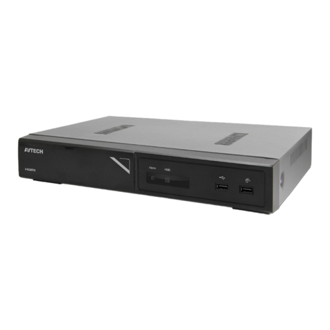
Crest Electronics CDVS-4100 Series User manual

CDVS-4100 Series
Embedded DVR
Setup And
Users Manual
Crest Electronics, Inc.
Version 05.23.06

i
Caution
This installation should be performed by qualified service personnel and should conform to all Federal State
and local laws.
WARNING: This equipment has been tested and found to comply with the limits for a Class B digital
device, pursuant to Part 15 of the FCC rules. These limits are designed to provide reasonable protection
against harmful interference in a residential installation. This equipment generates and uses radio
frequency energy, and if not installed and used in accordance with instructions, may cause harmful
interference to radio communications. However, there is no guarantee that the interference will not
occur in a particular installation. If this equipment does cause harmful interference to radio or television
reception, which can be determined by turning the equipment off and on, the user is encouraged to try to
correct the interference by one of the following methods:
- Relocate the receiving antenna
- Increase the amount of space between the equipment and the receiver.
- Connect the equipment to an outlet which is on a separate circuit than that of the
receiver.
- Consult the dealer or an experienced radio/TV technician for help
CAUTION: Changes or modifications not expressly approved by the party responsible for compliance
with the FCC Rules could void the user’s authority to operate this equipment.
RISK OF ELECTRIC SHOCK
DO NOT OPEN
CAUTION
CAUTION: TO REDUCE THE RISK OF ELECTRIC
SHOCK. DO NOT REMOVE COVER. NO
USER-SERVICEABLE PARTS INSIDE. REFER
SERVICING TO QUALIFIED SERVICE
PERSONNEL.
The lightning flash with arrowhead symbol, within an
equilateral triangle is intended to alert the user to the
presence of uninsulated dangerous voltage within the
product’s enclosure that may be of sufficient magnitude
to constitute a risk of electric shock to persons.
The exclamation point within an equilateral triangle is
intended to alert the user to the presence of important
operating and maintenance (servicing) instructions in
the literature accompanying the appliance.
WARNING: TO REDUCE THE RISK OF ELECTRICAL SHOCK, DO NOT EXPOSE THIS
APPLIANCE TO RAIN OR MOISTURE

ii
Important Safeguards
Warning
1. Turn off power to the unit prior to changing the battery.
2. Check the polarity of the lithium battery while changing.
3. When changing battery use the same type as original or similar type recommended by your vendor.
4. Dispose of old battery in accordance with the manufacturer of the battery.
General Warning
Warning
1. Use the power cord which is supplied or recommended by the manufacturer. Failure to do so could cause
a fire.
2. Use the power transformer which is supplied or recommended by the manufacturer. Failure to do so
could cause a fire.
3. Do not dismantle or assemble the product. Doing so could cause malfunction or fire.
4. Service should only be done by manufacturer or authorized vendor. Electrical shock or fire could result if
repair is not done properly.
5. Do not touch product with wet hands as electric shock may occur.
6. Product must be installed by a qualified professional. Failure to do so could result in malfunction,
electrical shock or fire.
7. Consult the place of purchase if the need for installation arises. Poor installation could cause
malfunction, electric shock or fire.
8. Ground applies to video products equipped with a 3-wire grounding type plug having a third (grounding)
pin. This plug only fits into a grounding type power outlet. If grounding is not done, equipment malfunc-
tion or electric shock may occur.
9. Ground connection must not touch gas pipe, water pipe or telephone lines.
10. Prevent foreign metallic substance from going inside the product. Failure to do so could result in mal-
function or electric shock.
11. Prevent water or other liquids from entering inside the product. Use damp cloth to clean outside of
product. Failure to do so could result in malfunction or electric shock.

iii
Caution
1. Use the power cord and power transformer supplied by the manufacturer or one recommended by the
manufacturer.
2. The internal fan rotates at high speed and may cause injury.
3. Do not drop, give unit strong vibration or shock to the product; doing so will cause malfunction.
4. Slots and openings in the front and back of the cabinet are provided for ventilation, to ensure reliable
operation of the unit, and to protect it from overheating. These openings must not be blocked or covered.
The openings should never be blocked by placing the unit on a bed, sofa, rug or similar surface. The unit
should never be placed near or over a radiator or heat source. This unit should not be placed in a built-
in installation such as a bookcase or rack unless proper ventilation is provided and/or the manufacturer’s
instructions are adhered to.
5. Do not install the product near or on top of heating source. The internal temperature of the product would
be greater than the allowable and could cause malfunction or fire.
6. Do not install the product on inclined or unstable locations such as an unstable cart, slant tripod, bracket,
or table. The unit may fall, causing serious injury, and serious damage to the unit.
Cautions about the Power
Warning
1. This unit should be operated only from the type of power indicated on the power plate. If you are not
sure of the type of power supply at your location, consult your dealer or local power company. For units
intended to operate from battery power, or other sources, refer to the operating instructions.
2. Power supply cords should be routed so that they are not likely to be walked on or pinched by items
placed upon or against them, paying particular attention to the cord at plugs, convenience receptacles,
and the point where they exit from the appliance.
3. Do not cut power cord to connect in the middle of the power cord or use extension cord. Doing so could
generate heat or cause fire.
4. Do not touch power cord in wet area or with wet hands.
5. Hold the body of the plug when removing the power cord. Do not pull cord as doing so may generate
heat or cause fire.
6. Remove the power cord from the outlet when not in use for long periods of time. This will prevent
damage to unit due to lightning and power line surges.

iv
Contents
Box Contents .................................................................................................1-1
Hardware Setup ....................................................................... 2-1
4108 8 Channel Embedded DVR ....................................................................2-1
4108 8 Channel Embedded DVR ....................................................................2-2
4104 4 Channel Embedded DVR ....................................................................2-3
e Embeded DVR Data Input and Output Terminal Pin Assignment........2-4
Description of Hardware Connestions ...........................................................2-5
Powering Up e DVR For e First Time ............................ 3-1
Default User Name and Password ...................................................................3-1
Setting e Time Zone....................................................................................3-2
Different Time Zones Around the World .......................................................3-3
Default Settings ...............................................................................................3-5
Controlling the DVR ..................................................................................4-1
Using e Remote Controller. ........................................................................4-1
Setting the ID on the remote controller .........................................................4-2
Front Panel Functions .....................................................................................4-4
Screen Display ...............................................................................................5-1
Camera Sequence ............................................................................................5-3
Overview of the Main Screen .................................................................6-1
Symbols ............................................................................................................6-1
Channel Swapping ...........................................................................................6-2
Main System Menu Pop Up Box ............................................................7-1
Overview of Pop Up Menu ..............................................................................7-1
Setting Up e DVR........................................................................................7-2
e System Menu.............................................................................................7-3
System (Information) screen ........................................................................7-3
System (Time Setup) Screen .........................................................................7-4
System (Disk Manager) .................................................................................7-5
System (User Account) ..................................................................................7-6
System (Covert Cameras) .............................................................................7-7
System (Factory Default Function) ..............................................................7-7
System (Log Off)...........................................................................................7-7
System (Shut Down) .....................................................................................7-7
e Device Menu ............................................................................................7-8
Device (Camera) Screen ...............................................................................7-8
Device (Camera) PTZ Setup .......................................................................7-10
Device (Camera) Color Control ................................................................7-11
Device (Camera) Audio ..............................................................................7-11
Device (Alarm) ...........................................................................................7-12
Device (Alarm) Sensor ...............................................................................7-12

v
Device (Alarm) Motion ..............................................................................7-14
Device (Alarm) Video Loss ........................................................................7-14
Device (Alarm) System ...............................................................................7-15
e Record Menu ..........................................................................................7-16
Record (Setup) ............................................................................................7-17
Motion Area Setup Window .......................................................................7-18
Record (Schedule) .......................................................................................7-19
Network ........................................................................................................7-21
Network (IP Setup) .....................................................................................7-21
TCP/IP Information ...................................................................................7-22
Network (E-Mail Notification) ...................................................................7-22
Network (Web Server Setup) ......................................................................7-23
Event Menu ....................................................................................................7-24
Searching Recorded Video ...................................................... 8-1
Search Menu ....................................................................................................8-1
Event (Calendar Search) ...............................................................................8-2
Search (Motion Search) ...............................................................................8-3
Search (Event Search) ...................................................................................8-4
Playback Screen Functions ..............................................................................8-5
Backing Up Recorded Video ................................................... 9-1
Digital PTZ .............................................................................10-1
Dynamic PTZ .........................................................................11-1

1-1
Contents
Please check the package for the following items. If any items are missing please contact your dealer.
• 4100 DVR
• Power cord
• Remote controller
• USB Mouse
• Utilities Disk
• Looping Output Cable (16 channel only)
CDVS-4100 Remote Controller
Utilities CD Looping Output Cable
16 channel only.
USB Mouse

2-1
Hardware Setup
is section describes the front and back connections of the CDVS-4116, 4108, 4104 Embedded DVR.
USB PortsCD-RW Drive Front Panel Controls
On/Off Button
Video Output
cable connection
Video Inputs 1 - 16
Spot monitor
Output
Audio Out Audio Input Power On/Off
Power plug
connection
Sensor/Relay/Ground/
422/485 connections
LAN connection
Two way
Audio
In/Out
NTSC/
PAL
Mon.
out
S-Video
Out
VGA
out
USB
ports
Front Panel Controls
Back Panel Controls
4108 8 Channel Embedded DVR
e images that follow show the hardware connections for the 16 channel embedded DVR.

2-2
4108 8 Channel Embedded DVR
e images that follow show the hardware connections for the 8 channel embedded DVR.
Video Outputs 1 - 8
Video Inputs 1 - 8
Spot monitor
Output
Audio Out Audio Input Power On/Off
Power plug
connection
Sensor/Relay/Ground/
422/485 connections
LAN connection
Two way
Audio
In/Out
NTSC/
PAL
Mon.
out
S-Video
Out
VGA
out
USB
ports
USB Ports
CD-RW Drive Front Panel Controls
On/Off Button
Front Panel Controls
Back Panel Controls

2-3
Video Outputs 1 - 4
Video Inputs 1 - 4
Spot monitor
Output
Audio Out Audio Input Power On/Off
Power plug
connection
Sensor/Relay/Ground/
422/485 connections
LAN connection
Two way
Audio
In/Out
NTSC/
PAL
Mon.
out
S-Video
Out
VGA
out
USB
ports
4104 4 Channel Embedded DVR
e images that follow show the hardware connections for the 4 channel embedded DVR.
USB Ports
CD-RW Drive Front Panel Controls
On/Off Button
Front Panel Controls
Back Panel Controls

2-4
28 27 26 25 24 23 22 21 20 19 18 17 16 15
1 2 3 4 5 6 7 8 9 10 11 12 13 14
e Embeded DVR Data Input and Output Terminal Pin Assignment
e drawing below shows the pin assignments for the sensors, relays and PTZ RS 485 data port.
Pin No. Signal Name Pin No. Signal Name
1 Sensor 15 15 Sensor 14
2 Sensor 16 16 Sensor 13
3 Common 17 Sensor 12
4 Common 18 Sensor 11
5 Relay 1-A 19 Sensor 10
6 Relay 1-B 20 Sensor 9
7 Relay 2-A 21 Sensor 8
8 Relay 2-B 22 Sensor 7
9 Relay 3-A 23 Sensor 6
10 Relay 3-B 24 Sensor 5
11 Relay 4-A 25 Sensor 4
12 Relay 4-B 26 Sensor 3
13 RS-485 + 27 Sensor 2
14 RS-485 - 28 Sensor 1

2-5
Description of Hardware Connestions
Video Input BNCs
Use the BNC connection to connect the BNC cable from the camera to the DVR.
Audio Output
Use this connection to connect to (optional) external speakers.
Spot Monitor Output
Use this port to connect an external (optional) spot monitor to the DVR.
Audio Inputs
ese ports are used to connect external (optional) microphones to the DVR.
Looping Output Connection
Use this connection to connect the looping octopus cable. is is used to loop out the video signal to other
equipment.
USB Ports
Use the USB ports to connect the USB mouse (supplied) for use with the DVR. You can also connect an
(optional) external USB hard drive or (optional) thumb disk for use with the DVR.
VGA Monitor
Used to connect the VGA monitor (not supplied) to view DVR
S-Video Input
Use this connection to connect an (optional) analog S-video monitor to the DVR.
Analog Monitor Connection
Use this connection to connect an (optional) analog monitor to the DVR
PAL / NTSC
Use this switch to select video format, either PAL or NTSC.
Two way audio
Use these inputs to connect the two way audio feature of the DVR. Connect (optional) microphone to in jack
and (optional) speaker to out jack.
RJ45 Lan Connection
Use either of these jacks to connect to a Local Area Network.
Alarm Sensor
Use these connections to connect alarms and relays to the DVR. is connection is also used to connect PTZ
cameras to the DVR via a 422/485 connection.
Power Switch
e power switch is used to supply power to the DVR.

3-1
Powering Up e DVR For e First Time
e default settings of the 4100 series DVR will allow the DVR to begin recording in continuous mode aer
all the hardware has been installed and the unit is powered on. e steps below will walk you through setting
the date and time for your unit.
Aer making all connections to the DVR, turn on the DVR by pushing the on/off button located on the front
panel of the DVR. e system will go through a series of self diagnostics aer which, will bring up the main
screen. If you have not connected cameras to all the ports, you will receive a loss signal warning. Click OK to
move past the warning screen. See image below.
Click Yes to remove message from screen
Default User Name and Password
Click the right mouse button or press the menu button on the front panel or remote controller. is will
bring up the log in screen. e system default user is administrator and the password is 1234. Use the mouse
to click the password 1 2 3 4 and click OK. See image below.

3-2
Setting e Time Zone
e time zone can be set for the area in which you live by following the directions below. From the Main
Menu click the Time Setup button as shown in image below.
Click Time Setup
From the Time Setup Menu shown below set the Time Zone, Date Format, Date and Time for your particu-
lar area. Time zone is shown from Greenwich Mean Time. A listing of the different time zones can be seen in
the table that follows.
Note: Failure to set time and time zone when first installing the DVR can lead to lost video when you set the
date and time aer recording has taken place.

3-3
Different Time Zones Around the World
e chart below shows the amount of time + or - from Greenwich Mean Time. is will help you in setting
your particular time zone.
(GMT - 12:00) Eniwetok, Kwajalein
(GMT - 11:00) Midway Island, Samoa
(GMT - 10:00) Hawaii
(GMT - 09:00) Alaska
(GMT - 08:00) Pacific Time (US & Canada); Tijuana
(GMT - 07:00) Arizona
(GMT - 07:00) Mountain Time (US & Canada)
(GMT - 06:00) Central America
(GMT - 06:00) Central Time (US & Canada)
(GMT - 06:00) Mexico City
(GMT - 06:00) Saskatchewan
(GMT - 05:00) Bogotá, Lima, Quito
(GMT - 05:00 Eastern Time (US & Canada)
(GMT - 05:00) Indiana (East)
(GMT - 04:00) Atlantic Time (Canada)
(GMT - 04:00) Caracas, La Paz
(GMT - 04:00) Santiago
(GMT - 03:30) Newfoundland
(GMT - 03:00) Brasilia
(GMT - 03:00) Buenos Aries, Georgetown
(GMT - 03:00) Greenland
(GMT - 02:00) Mid Atlantic
(GMT - 01:00) Azores
(GMT - 01:00) Cape Verde Is.
(GMT) Casablanca, Monrovia
(GMT ) Greenwich Mean Time : Dublin, Edinburgh, Lisbon, London
(GMT + 01:00) Amsterdam, Berlin, Bern, Rome, Stockholm, Vienna
(GMT + 01:00) Belgrade, Bratislava, Budapest, Ljubljana, Prague
(GMT + 01:00) Brussels, Copenhagen, Madrid, Paris
(GMT + 01:00) Sarajevo, Skopje, Vilnius, Warsaw, Zagreb
(GMT + 01:00) West Central Africa
(GMT + 02:00) Athens, Istanbul, Minsk
(GMT + 02:00) Bucharest
(GMT + 02:00) Cairo
(GMT + 02:00) Harare, Pretoria
(GMT + 02:00) Helsinki, Riga, Tallinn
(GMT + 02:00) Jerusalem
(GMT + 03:00) Baghdad
(GMT + 03:00) Kuwait, Riyadh
(GMT + 03:00) Moscow, St. Petersburg, Volgograd
(GMT + 03:00) Nairobi
(GMT + 03:30) Tehran
(GMT + 04:00) Adu Dhabi, Muscat
(GMT + 04:00) Baku, Tbilisi, Verevan
(GMT + 04:30) Kabul

3-4
(GMT + 05:00) Ekaterinburg
(GMT + 05:00) Islamabad, Karachi, Tashkent
(GMT + 05:45) Kathmandu
(GMT + 06:00) Almaty, Novosibirsk
(GMT + 06:00) Astana, Dhaka
(GMT + 06:00) Sri Jayawardenepura
(GMT + 06:30) Rangoon
(GMT + 07:00) Bangkok, Hanoi, Jakarta
(GMT + 07:00) Krasnoyarsk
(GMT + 08:00) Beijing, Chongqing, Hong Kong, Urumqi
(GMT + 08:00) Irkutsk, Ulaan Bataar
(GMT + 08:00) Kuala Lumpur, Singapore
(GMT + 08:00) Perth
(GMT + 08:00) Taipei
(GMT + 09:00) Osaka, Sapporo, Tokyo
(GMT + 09:00) Seoul
(GMT + 09:00) Yakutsk
(GMT + 09:30) Adelaide
(GMT + 09:30) Darwin
(GMT + 10:00) Brisbane
(GMT + 10:00) Canberra, Melbourne, Sydney
(GMT + 10:00) Guam, Port Moresby
(GMT + 10:00) Hobart
(GMT + 10:00) Vladivostok
(GMT + 11:00) Magadan, Solomon Is., New Caledonia
(GMT + 12:00) Auckland, Wellington
(GMT + 12:00) Fiji, Kamchatka, Marshall Is.
(GMT + 13:00) Nuku’alofa

3-5
Default Settings
e following is a listing of the default settings for the DVR.
• All cameras turned on
• Resolution set to 1 CIF
• Each camera set to 8 FPS
• Image quality set to high
• Recording mode set to continuous
• Pre Alarm set to off
• Post Alarm set to off
• Overwrite set to on
• Remote controller ID set to 0
• Time Zone set to (GMT - 12)
• Date format set to YY-MM-DD
• Audio channel 1 set not used
• Audio channel 2 set not used
• Audio channel 3 set not used
• Audio channel 4 set not used
• Two Way Audio set off
• Alarm set enabled
• Alarm contact set to normally open
• Alarm dwell set to 5 sec.
• On Screen Display
Camera title enabled
HDD indicator enabled
Motion Detection enabled
Date and time enabled
FPS disabled
Temp indicator enabled
Audio connection enabled

4-1
Controlling the DVR
ere are three ways to control the DVR; using the USB mouse, using the remote controller, or using the
front panel. is section will provide you an overview of the functions used with the remote controller and
the front panel.
Using e Remote Controller.
e remote controller can be used to control the various functions of the DVR. e controller and DVR
come preset to ID 0. If more than one DVR is used at the same location you can set a different ID for each
DVR and controller. See section later in this chapter on how to do this. e following image shows the fea-
tures of the remote controller.
Power Button: Turns DVR on and off
ID button: used to set controller ID
ID set button: Used to
set controller ID
Numeric keypad: used
to input controller ID
Up button: Used to move
the on screen cursor up
Le button: used to move the
on screen cursor to the le
Right button: Used to move
on screen cursor to the right
Down button: Used to move
the on screen cursor down
Esc button: Used to back out of a command
Enter button: Used to select a command
Zoom Int button: Used to zoom a PTZ camera
Mode button: Used to select
the screen display mode
Record button
Pause button
Advance frame forward
Menu button: Brings up the menu screen
Puts the system in PTZ mode
Search button: Used to bring up the search screen
Zoom Out button
Seq button: Used to put DVR in sequence mode
Play backward
Play forward
Play fast backward
Backward one frame
Play fast forward

4-2
Setting the ID on the remote controller
e controller ID can be set from 00-99; is is useful when there are two DVR in close proximity to each
other. e two controllers can be set to use two different ID so they will not interfere with each other.
e controller ID must be set in both the remote controller and the DVR. To set the ID on the controller, fol-
low the instructions below:
1) Push and hold the ID button until the red light stays on.
2) Enter the number on the numeric key pad you wish to set as the ID. To use 0-9 you must enter 0
in front of number. Example to set ID to 1, enter 01 in the controller.
3) Press the ID set button; the controller’s red light will blink 3 times and go off. e controller is
now set.
You must now set the ID in the DVR. is can be done using the front panel or the mouse. Follow the in-
structions below for setting the controller ID in the DVR:
1) If you have not logged into the DVR, do so now.
2) Push the menu button on the front panel or right click the mouse button. e menu screen
appears. Click Main Menu. (See Image below.)
Click main menu

4-3
3) Click Main Menu to enter the System Menu. (See image below).
System Menu
Select Information Menu
4) Click the Information Menu bar, the System Information screen appears (see below).
System Information Menu
Click the up or down
arrows to move the ID
number
5) Click the up or down arrows to change the setting for the controller ID. Aer changing the ID,
click the OK button to save the change. Click OK at the system menu to get to the main screen.
6) e remote controller is now ready for use.
This manual suits for next models
3
Table of contents
Other Crest Electronics DVR manuals
Crest Electronics
Crest Electronics CDVS-7000 User manual

Crest Electronics
Crest Electronics CDVS-7000 User manual
Crest Electronics
Crest Electronics CDVS-5400 SERIES User manual

Crest Electronics
Crest Electronics CDVS-7000 User manual
Crest Electronics
Crest Electronics CDVS-5000 Series User manual

Crest Electronics
Crest Electronics CDR-1104 User manual

Crest Electronics
Crest Electronics CDR-1104 User manual
