Crest Electronics CDVS-7000 User manual

CDVS-7000 Series
DVR Setup And
Users Manual
Crest Electronics, Inc.
Version 02.28.06

i
Caution
This installation should be performed by qualified service personnel and should conform to all Federal, State
and local laws.
WARNING: This equipment has been tested and found to comply with the limits for a Class B digital
device, pursuant to Part 15 of the FCC rules. These limits are designed to provide reasonable protection
against harmful interference in a residential installation. This equipment generates and uses radio
frequency energy, and if not installed and used in accordance with instructions, may cause harmful
interference to radio communications. However, there is no guarantee that the interference will not
occur in a particular installation. If this equipment does cause harmful interference to radio or television
reception, which can be determined by turning the equipment off and on, the user is encouraged to try to
correct the interference by one of the following methods:
- Relocate the receiving antenna
- Increase the amount of space between the equipment and the receiver.
- Connect the equipment to an outlet which is on a separate circuit than that of the
receiver.
- Consult the dealer or an experienced radio/TV technician for help
CAUTION: Changes or modifications not expressly approved by the party responsible for compliance
with the FCC Rules could void the user’s authority to operate this equipment.
RISK OF ELECTRIC SHOCK
DO NOT OPEN
CAUTION
CAUTION: TO REDUCE THE RISK OF ELECTRIC
SHOCK. DO NOT REMOVE COVER. NO
USER-SERVICEABLE PARTS INSIDE. REFER
SERVICING TO QUALIFIED SERVICE
PERSONNEL.
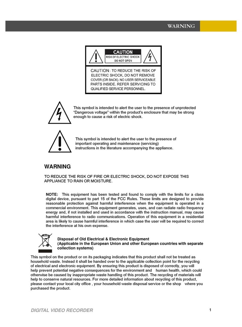
The lightning flash with arrowhead symbol, within an
equilateral triangle is intended to alert the user to the
presence of uninsulated dangerous voltage within the
product’s enclosure that may be of sufficient magnitude
to constitute a risk of electric shock to persons.
The exclamation point within an equilateral triangle is
intended to alert the user to the presence of important
operating and maintenance (servicing) instructions in
the literature accompanying the appliance.
WARNING: TO REDUCE THE RISK OF ELECTRICAL SHOCK, DO NOT EXPOSE THIS
APPLIANCE TO RAIN OR MOISTURE

ii
Important Safeguards
Warning
1. Turn off power to the unit prior to changing the battery.
2. Check the polarity of the lithium battery while changing.
3. When changing battery use the same type as original or similar type recommended by your vendor.
4. Dispose of old battery in accordance with the manufacturer of the battery.
General Warning
Warning
1. Use the power cord, which is supplied or recommended by the manufacturer. Failure to do so could cause
a fire.
2. Use the power transformer, which is supplied or recommended by the manufacturer. Failure to do so
could cause a fire.
3. Do not dismantle or assemble the product. Doing so could cause malfunction or fire.
4. Service should only be done by manufacturer or authorized vendor. Electrical shock or fire could result if
repair is not done properly.
5. Do not touch product with wet hands as electric shock may occour.
6. Product must be installed by a qualified professional. Failure to do so could result in malfunction,
electrical shock or fire.
7. Consult the place of purchase if the need for installation arises. Poor installation could cause
malfunction, electric shock or fire.
8. Ground applies to video products equipped with a 3-wire grounding type plug having a third (grounding)
pin. This plug only fits into a grounding type power outlet. If grounding is not done, equipment malfunc
tion or electric shock may occur.
9. Ground connection must not touch gas pipe, water pipe or telephone lines.
10.Prevent foreign metallic substance from going inside the product. Failure to do so could result in mal
function or electric shock.
11. Prevent water or other liquids from entering inside the product. Use damp cloth to clean outside of
product. Failure to do so could result in malfunction or electric shock.

iii
Caution
1. Use the power cord and power transformer supplied by the manufacturer or one recommended by the
manufacturer.
2. The internal fan rotates at high speed and may cause injury.
3. Do not drop, give unit strong vibration or shock to the product; doing so will cause malfunction.
4. Slots and openings in the front and back of the cabinet are provided for ventilation, to ensure reliable
operation of the unit, and to protect it from overheating. These openings must not be blocked or covered.
The openings should never be blocked by placing the unit on a bed, sofa, rug or similar surface. The unit
should never be placed near or over a radiator or heat source. This unit should not be placed in a built-
in installation such as a bookcase or rack unless proper ventilation is provided and/or the manufacturer’s
instructions are adhered to.
5. Do not install the product near or on top of heating source. The internal temperature of the product would
be greater than the allowable and could cause malfunction or fire.
6. Do not install the product on inclined or unstable locations such as an unstable cart, slant tripod, bracket,
or table. The unit may fall, causing serious injury, and serious damage to the unit.
Cautions about the Power
Warning
1. This unit should be operated only from the type of power indicated on the power plate. If you are not
sure of the type of power supply at your location, consult your dealer or local power company. For units
intended to operate from battery power, or other sources, refer to the operating instructions.
2. Power supply cords should be routed so that they are not likely to be walked on or pinched by items
placed upon or against them, paying particular attention to the cord at plugs, convenience receptacles,
and the point where they exit from the appliance.
3. Do not cut power cord to connect in the middle of the power cord or use extension cord. Doing so could
generate heat or cause fire.
4. Do not touch power cord in wet area or with wet hands.
5. Hold the body of the plug when removing the power cord. Do not pull cord as doing so may generate
heat or cause fire.
6. Remove the power cord from the outlet when not in use for long periods of time. This will prevent
damage to unit due to lightning and power line surges.

i
Contents
Chapter 1
Overview of Main Screen
Image Display Area ............................................................................... 1-1
Camera Display Buttons ............................................................................... 1-2
Display Next Screen Button ............................................................................... 1-3
Auto Rotate ............................................................................... 1-3
Full Screen Mode ............................................................................... 1-3
Snapshot Button ............................................................................... 1-4
Live Audio Button ............................................................................... 1-4
Audible Alarm Mute Button ............................................................................... 1-4
Current Date and Time ............................................................................... 1-5
Change Date and Time ............................................................................... 1-5
Camera Display Bar ............................................................................... 1-6
User Log On ............................................................................... 1-6
Network Connection Button ............................................................................... 1-7
Relay/Control Button ............................................................................... 1-7
Sensor Button ............................................................................... 1-7
Channel Swapping ............................................................................... 1-8
Partial Zoom ............................................................................... 1-8
Quick Search Function ............................................................................... 1-9
Quick search by date and time ............................................................................... 1-10
Image Screen Pop Up Menu ............................................................................... 1-10
Search Menu Button ............................................................................... 1-11
Setup Menu Button ............................................................................... 1-11
Motion Setup Button ............................................................................... 1-11
Emergency Record Button ............................................................................... 1-12
PTZ Button ............................................................................... 1-12
E-map Button ............................................................................... 1-12
Chapter 2
Search Screen Functions
Search Screen Menus ............................................................................... 2-1
Using the Search Screen ............................................................................... 2-2
Playback Screen ............................................................................... 2-2
Screen Swapping ............................................................................... 2-2
Playback Screen Shortcuts ............................................................................... 2-3
Partial Zoom ............................................................................... 2-3
Section Color ............................................................................... 2-4
Brightness Mode ............................................................................... 2-4

ii
Invert Mode ............................................................................... 2-4
Field Mode ............................................................................... 2-5
Screen Division ............................................................................... 2-5
Full ............................................................................... 2-5
Exit ............................................................................... 2-5
Screen Display Buttons ............................................................................... 2-6
Playback Control Buttons ............................................................................... 2-6
Camera Selection Buttons ............................................................................... 2-6
Speed, Brightness, Contrast, & Audio Control ...................................................... 2-7
Zoom ............................................................................... 2-7
Date Calendar ............................................................................... 2-7
Time Control Bar ............................................................................... 2-8
Exit Button ............................................................................... 2-8
Chapter 3
Backing up Data on the CDVS-7000 Series DVR
Navigating to the Backup Menu ............................................................................... 3-1
Using Smart Backup ............................................................................... 3-2
Detail Description of the Smart Backup Screen ..................................................... 3-3
Recorded Data Screen ............................................................................... 3-3
Step By Step Examples of Smart Backup ................................................................. 3-8
AVI Backup ............................................................................... 3-18
Media Backup ............................................................................... 3-19
AVI Capture ............................................................................... 3-21
JPG Capture ............................................................................... 3-21
Event Search ............................................................................... 3-23
Log Viewer ............................................................................... 3-25
Motion Search ............................................................................... 3-27
Data Path ............................................................................... 3-32
Bookmark ............................................................................... 3-33
Watermark ............................................................................... 3-33
Snapshot ............................................................................... 3-34
Chapter 4
SYSTEM SETUP
Camera Setup ............................................................................... 4-1
Import/Export ............................................................................... 4-4
Sensor Setup ............................................................................... 4-5
Relay Setup Window ............................................................................... 4-7
Recording Schedule Setup Window ........................................................................ 4-9
Network Setup Window ............................................................................... 4-19
User Setup Window ............................................................................... 4-22
Information Window ............................................................................... 4-25

iii
Chapter 5
PTZ Function
PTZ connection ............................................................................... 5-1
PTZ Function Controls ............................................................................... 5-2
Preset Tour Setup Screen ............................................................................... 5-4
Controlling e PTZ Camera ............................................................................... 5-6
Setting Presets ............................................................................... 5-7
Calling a Preset ............................................................................... 5-7
Chapter 6
Backup Player
Backup Player ............................................................................... 6-1
Overview of the Backup Player Screen .................................................................... 6-3
Functions Buttons ............................................................................... 6-4
Playback Controls ............................................................................... 6-4
Date Calendar ............................................................................... 6-5
Time Control Bar ............................................................................... 6-5
Zoom ............................................................................... 6-6
Using Data Path ............................................................................... 6-6
Partial Zoom ............................................................................... 6-7
Field Mode ............................................................................... 6-9
Screen Division ............................................................................... 6-9
Full ............................................................................... 6-9
Exit ............................................................................... 6-9
Backup Function ............................................................................... 6-10
AVI Backup ............................................................................... 6-10
Media Backup ............................................................................... 6-11
AVI Capture ............................................................................... 6-13

Chapter 1
Overview of Main Screen
1

1-1
Overview of Main Screen
This section describes the main screen and its menu buttons. The image below details the name
of the buttons.
Image Display Area
The image display area displays the live images of the current cameras. This display can be
changed by clicking on the screen division buttons (see screen division section on the different
views available). To change the screen from multi camera view to single camera view, double
click the left mouse button in the image you want to bring up in single view, or click in the image
making it the selected camera (will be highlighted in red), then click the single camera division
button. To change back, double click within the image. Each image displays the camera name
and the recording mode in use at the top of every image. The various modes are: C - Continuous
recording, S - Sensor recording, M - Motion recording, MS - Motion and Sensor recording, N
- No recording. (To change these settings please see Scheduling in Chapter 4, System Setup)
Screen Division and control
Network Connections
Relays
Sensors
Current Date and Time
Search
Setup
Motion
Emergency record
PTZ control and setup
E-Map
Snapshot
Audio on/off
Mute Alarm
System Exit
User Logon
Recording Mode
Display Camera Selection
Image Display Area

1-2
Camera Display Buttons
The following is a description of the different views available in the Crest CDVS-7000 series
DVR software.
This will allow the user to view only one camera at a time. To view a single camera, left click
highlighting the desired camera in a red outline. Next, left click the single camera display button.
The selected camera will replace the current view with a single camera view. To have the sys-
tem rotate from one camera to another, click the Next button. To have the system automatically
change from one camera to another, click the Auto Rotate button (see below).
4 Camera Display Button
This will allow the user to view four cameras at a time. The system displays the cameras in
the following configurations: cameras 1,2,3,4, cameras 5,6,7,8, cameras 9,10,11,12, cameras
13,14,15,16. To have the system rotate from one 4 camera view to another, click the Next but-
ton. To have the system automatically change from one 4 camera view to another, click the Auto
Rotate button (see below).
6 Camera Display Button
This will allow the user to display six cameras at a time. The different configurations are: camer-
as 1 - 6, 7 - 12, and 11 - 16. To view, click on one of the cameras you want to view and click the
6 camera display button. To have the system rotate from one 6 camera view to another, click the
Next button. To have the system automatically change from one 6 camera view to another, click
the Auto Rotate button (see below).
9 Camera Display Button
This will allow the user to display nine cameras at a time. The different configurations are:
cameras 1 - 9, and 8 - 16. To view, click on one of the cameras you want to view and click the 9
camera display button. To have the system rotate from one 9 camera view to another, click the
Next button. To have the system automatically change from one 9 camera view to another, click
the Auto Rotate button (see below).
Single Camera Display Button

1-3
10 Camera Display Button
This will allow the user to display ten cameras at a time. The different configurations are: cam-
eras 1 - 10, and 7 - 16. To view, click on one of the cameras you want to view and click the 10
camera display button. To have the system rotate from one 10 camera view to another, click the
Next button. To have the system automatically change from one 10 camera view to another, click
the Auto Rotate button (see below).
13 Camera Display Button
This will allow the user to display thirteen cameras at a time. The different configurations are:
cameras 1 - 13, and 4 - 16. To view, click on one of the cameras you want to view, and click the
13 camera display button. To have the system rotate from one 13 camera view to another, click
the Next button. To have the system automatically change from one 13 camera view to another,
click the Auto Rotate button(see below).
16 Camera Display Button
This will allow the user to display 16 cameras at a time.
Display Next Screen Button
If you are in any other screen display mode other than 16 camera display, use this button to go to
the next display configuration. By repeatedly clicking this button you will rotate through all the
available display screens for the currently selected screen division.
Auto Rotate
This button is used to have the system automatically rotate through the available screens for the
currently selected screen division (see system setup section for more details).
Full Screen Mode
This button is used to hide the GUI. Click this button to have the live images go full screen.

1-4
Snapshot Button
This function allows the user to capture a snapshot of the live screen. Click this button to take a
snapshot of the current live screen. After clicking, the snapshot interface will come on screen as
shown below. Snapshot allows you to manipulate the contrast, brightness, flip or mirror the im-
age. You can save, print or email the image. Printing requires that you have a printer connect and
set up on the DVR. E-Mail requires that you have an email account and email set up on the DVR.
LIVE SNAPSHOT VIEW IN 4 CAMERA DIVISION
Live Audio Button
This button turns live audio on and off. To listen to live audio, click on the desired camera (im-
age will be highlighted in red) and click the audio button (button will turn blue). To listen to an-
other microphone, click in the image (will become highlighted in red) where the desired audio is
linked. To stop listening to live audio, click the audio button (button will turn from blue to gray).
Please see the section on setting up audio in the Setup Chapter.
Audible Alarm Mute Button
This feature allows you to turn off the audible alarm. See Setup section for setting up alarms.

1-5
Current Date and Time
This is the system clock; it displays the current date and time.
change date warning
date and time screen
To change current date and time, double click inside the date and time screen. Caution: You
could lose data by changing the date and time
Change Date and Time
After clicking yes to the change date warning screen, the following screen appears allowing you
to change the system time or date. See image below.
change date
change date screen
apply and save changes exit date change
change time
Hour displayed in 24 hr format

1-6
Camera Display Bar
The camera display bar allows the user to see which camera is currently selected (currently se-
lected image will be highlighted in red). To change the selected camera, simply click the camera
number. The letters below the camera number indicate the recording mode the camera is cur-
rently in. The following is a list of recording modes:
C -Continuous recording
S - Sensor recording
M - Motion recording
MS - Motion and sensor recording
N - No recording
The recording mode is also displayed in the image at the top right corner of each image.
User Log On
To log on, click the lock in the left corner of the user login button.
The following screen will display allowing you to enter a user name and password. The factory
default user name is: system The password is: manager. Use caution when entering usernames
and passwords as they are case sensitive. The default password will work until a user is added
to the system. After a user has been added the default password will be disabled. If you should
forget your password, call the company that installed your DVR.
click here to log on.
enter user name
enter user password
click to login virtual keyboard

1-7
Network Connection Button
When the network connection button is highlighted, it means that there is a remote connection to
the DVR. To see who is connected, click this button to display the network connection screen. It
will list all connections to the DVR (see picture below).
Relay/Control Button
When a relay is activated, this button will flash. To bring
up the relay and sensor bar, click on this button. Acti-
vated relays will be highlighted.
Sensor Button
When a sensor is activated, this button will flash. To
see the sensor and relay bar, click this button. Active
sensors will be highlighted.
Sensor and Relay
display bar

1-8
Crest provides channel swapping function for user’s convenience. One channel position can be
swapped with another by clicking and dragging one channel to another. The swapped positions
are not permanent. The swapped channels are returned to their original positions when the user
chooses another screen division or the DVR is rebooted.
Channel Swapping
Crest CDVS-7000 series DVR system provides a partial zoom in function on both live and play-
back image. The area selected by clicking and dragging is expanded into the whole screen area.
Partial Zoom

1-9
Quick Search Function
The quick search function allows the user to view recorded video from one camera without leav-
ing the main screen. The system starts playback from the last recorded image and starts playing
video backwards. The quick search function allows the users to specify a date and time to review
video. To start quick search, select the camera you want to view (selected camera is the camera
image highlighted in red) by clicking in the image area. You could also select one of the camera
numbers at the bottom of the screen. After selecting the camera, right click in the image area.
This will bring up the live screen pop up menu.
Click Quick Search from the pop up menu. The quick search screen appears in the lower right
corner of the screen. Quick search searches for the last video recorded to the hard disk and starts
playing video backwards from that date. The following images show the quick search screen and
the functions of its buttons.
Date and time
of current
video
Camera
playing
Exit
Date & time
search
Back one
Play backwards
Advance one frame
Play forward
Pause

1-10
Quick search by date and time
User can search by date and time by clicking on the month, day, or year and advancing back-
ward or forward using the buttons to the right of the date bar. Do the same for the desired time.
Click the search button; Quick Search searches for that date and time. If there is recorded video,
it starts playing video back. If there is no video for the date and time selected, quick search will
playback the first recorded video after the requested time. Example: User chooses October 4,
2005 at 5:39:14 PM; quick search looks for video on that date and time, but cannot find any
recorded video. The system then begins searching for recorded video from the date and time en-
tered by the user. In this case 10/4/2005, 5:39:14 PM and going forward from that date and time
until it finds recorded video. It then starts playback from this point.
Quick Search assumes that the user wants to play back the most recent file or knows the date
and time of the requested video. For more comprehensive search features, please see Chapter 2
Search Screen Functions.
Image Screen Pop Up Menu
This pop up menu allows the user to access the different screen divisions, as well as quick search
and emergency record while the screen is in Full mode (No GUI showing). To return the GUI
to the screen, uncheck Full on the menu. Using the Emergency Record function on the pop up
menu allows the user to select only the current (highlighted) camera for Emergency Record. This
is different than using the emergency record button on the main screen which puts all cameras
in Emergency Record. The camera will continue to record in Emergency Record mode until the
user unchecks emergency record.
advance or move backward with these arrows
Search for video and begin playback

1-11
Search Menu Button
The search menu allows the user to playback and search for recorded video. The user can search
one or all cameras by date and time. During search the user can play video forward, backward,
fast or slow, or frame by frame. The user can change the brightness or contrast of the images dur-
ing playback. From this menu the user can do a backup of recorded video for all cameras or just
one camera. The backup function also allows for watermarking of the video, as well as exporting
video as an AVI file. The backup function allows the user to export a snapshot in JPEG format.
The search menu allows the user to bookmark an event allowing for easy retrieval at a later date.
Through the Search menu the user can do an event or motion search. Please see the Chapter 2
Search Screen Functions for details on these and other features available in the search menu.
Setup Menu Button
The setup menu is where the user sets up the system environment. These functions include
Camera setup, Sensor setup, Relay setup, scheduling of recording mode and time, setting of pre
and post alarm recording, the setting of channels for analog output, video database management,
network environment setup, user management and more. Please refer to the Chapter 4 System
Setup for detailed information on the different functions available in the setup menu.
Motion Setup Button
Click this button to set the motion fields for each image. The CDVS 7000 series allows the user
to have multiple sensitivity settings within the camera picture. Other systems will only allow a
single sensitive setting for each camera. This can cause problems if the field of view contains
elements requiring different sensitivity before triggering motion. This menu also allows the user
to adjust the brightness, contrast and saturation for each camera image displayed on the live view
screen. This menu allows the user to adjust the volume for the audio associated with each camera
(if used). Please see Chapter 4 System Setup for detailed information on using this menu.

1-12
Emergency Record Button
When clicked, the emergency record button will begin the continuous recording of all cameras.
After emergency recording has been activated, the record mode indicator will change to an E.
The system will continue recording in emergency mode until the emergency record button is
clicked a second time. Clicking this button will affect all cameras. To use emergency mode with
a single camera, right click in the image area bringing up the pop up menu and select emergency
record. To turn off, repeat actions and uncheck emergency record. Please see live screen pop up
menu earlier in the section for information on the other items in this menu.
PTZ Button
The PTZ button gives the user access to the Pan Tilt Zoom controller for controlling any PTZ
cameras which have been set up in the system. For information on PTZ setup, please refer to
Chapter 5 Set Up PTZ Function.
E-map Button
The E-map button allows the user to access any camera maps that may have been loaded into
the system. The function allows the user to create visual maps on which Sensor, Relay and/or
Camera icons may be placed. The sensor and relay icons will turn red and flash indicating that an
alarm has occurred. The user can then see, on the map, where in the building the alarm is coming
from, and can then click on a camera to view live images from that particular area. This feature
comes in handy in large buildings where all the images look the same, such as hallways. By us-
ing maps, the user can easily identify which area is giving the alarm.
Other manuals for CDVS-7000
2
Table of contents
Other Crest Electronics DVR manuals
Crest Electronics
Crest Electronics CDVS-5000 Series User manual

Crest Electronics
Crest Electronics CDR-1104 User manual
Crest Electronics
Crest Electronics CDVS-4100 Series User manual
Crest Electronics
Crest Electronics CDVS-5400 SERIES User manual
Crest Electronics
Crest Electronics CDVS-7000 User manual

Crest Electronics
Crest Electronics CDR-1104 User manual

Crest Electronics
Crest Electronics CDVS-7000 User manual

