Description
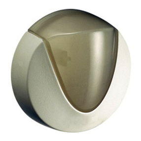
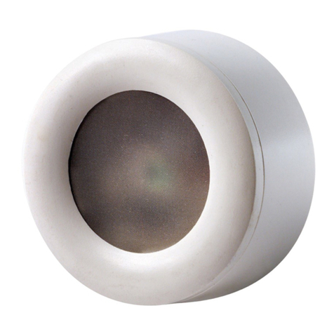
The IRP2, shown below,contains an infrared (IR) LED housed in a miniature, mouse shaped, black,
injection molded plastic shell. The IRP2 shell emits IR control signals sent to it by a Crestron®
control system. The shell can be installed directly on the IR sensor window of the controlled
device. It is also compatible with X-Generation controllers by exchanging the 3.5 mm connector
for a 5 mm connector (not supplied). It is not compatible with the CNMS generation.
Contents
In addition to the IRP2, this package also contains an IR mask and three pieces of two-sided tape.
Installation
Attaching the IRP2 to IR Sensor Window (Refer to Below)
1. Identify the clear adhesive layer on the flat bottom surface of the IRP2 shell.
2. Peel off the protective cover and affix the IRP2 to the center of the IR sensor window on the
controlled component’s front panel.
NOTE: In some cases it may be difficult to find the location of the IR sensor on the component.
Consult the owner’s manual of the unit, or the manufacturer, for the exact IR window location.
3. If the IRP2 shell must be removed and repositioned for any reason,it may be necessary to
replace the adhesive with a new piece of the two-sided tape (supplied) to restore adhesion.
Installing the IR Mask (Refer to Above)
The IR mask (supplied) is designed to fit over the IRP2 shell (shown in B above) so that the sensor
window of the controlled component is completely covered. It prevents unwanted external IR
signals from passing through or leaking past it. It also prevents IR emitted from the IRP2 shell from
radiating backward into the IR sensors of other nearby components.
1. Without removing the adhesive backing from the IRP2 shell or IR mask, fit the two pieces
together and accurately position them over the IR sensor window of the component to be
controlled.
2. If necessary, neatly trim the IR mask being sure that it overlaps the extremities of the
component’s IR sensor window.
3. Remove the adhesive backing from the IRP2 shell and IR mask and position them over the IR
sensor windows while pressing down firmly.
A
B
#LEAR!DHESIVE,AYER
!DHESIVE
)2-ASK
3IDE6IEW
)20
3HELL
!"
)NTERNAL)2
%MITTER
)2
/UTPUT
)2
/UTPUT
)20
-INIWIRE
,EAD
Connecting the IRP2
Insert the 2-pin connector of the IRP2 into an infrared-serial output port of the control system, or
other device as shown in the following illustration.
NOTE: The white-traced wire connects to the pin labeled S.
)23ENSOR
7INDOW
Projector
$-2-# 3'3'
Side View
Top View
FT
^M
FT
MM
IN
MM
IN
MM
IN
MM
0IN#ONNECTOR
./4%7HITESTRIPED
SIDEISPOSITIVE
Side View
Top View
FT
^M
FT
MM
IN
MM
IN
MM
IN
MM
0IN#ONNECTOR
./4%7HITESTRIPED
SIDEISPOSITIVE
Description
The IRP2, shown below,contains an infrared (IR) LED housed in a miniature, mouse shaped, black,
injection molded plastic shell. The IRP2 shell emits IR control signals sent to it by a Crestron®
control system. The shell can be installed directly on the IR sensor window of the controlled
device. It is also compatible with X-Generation controllers by exchanging the 3.5 mm connector
for a 5 mm connector (not supplied). It is not compatible with the CNMS generation.
Contents
In addition to the IRP2, this package also contains an IR mask and three pieces of two-sided tape.
Installation
Attaching the IRP2 to IR Sensor Window (Refer to Below)
1. Identify the clear adhesive layer on the flat bottom surface of the IRP2 shell.
2. Peel off the protective cover and affix the IRP2 to the center of the IR sensor window on the
controlled component’s front panel.
NOTE: In some cases it may be difficult to find the location of the IR sensor on the component.
Consult the owner’s manual of the unit, or the manufacturer, for the exact IR window location.
3. If the IRP2 shell must be removed and repositioned for any reason,it may be necessary to
replace the adhesive with a new piece of the two-sided tape (supplied) to restore adhesion.
Installing the IR Mask (Refer to Above)
The IR mask (supplied) is designed to fit over the IRP2 shell (shown in B above) so that the sensor
window of the controlled component is completely covered. It prevents unwanted external IR
signals from passing through or leaking past it. It also prevents IR emitted from the IRP2 shell from
radiating backward into the IR sensors of other nearby components.
1. Without removing the adhesive backing from the IRP2 shell or IR mask, fit the two pieces
together and accurately position them over the IR sensor window of the component to be
controlled.
2. If necessary, neatly trim the IR mask being sure that it overlaps the extremities of the
component’s IR sensor window.
3. Remove the adhesive backing from the IRP2 shell and IR mask and position them over the IR
sensor windows while pressing down firmly.
#LEAR!DHESIVE,AYER
!DHESIVE
)2-ASK
3IDE6IEW
)20
3HELL
!"
)NTERNAL)2
%MITTER
)2
/UTPUT
)2
/UTPUT
)20
-INIWIRE
,EAD
Connecting the IRP2
Insert the 2-pin connector of the IRP2 into an infrared-serial output port of the control system, or
other device as shown in the following illustration.
NOTE: The white-traced wire connects to the pin labeled S.
)23ENSOR
7INDOW
Projector
$-2-# 3'3'
A
B
