CREVIS GN-9222 User manual

1FnIO PROFIBUS Adapter GN-9222 FnIO G-Series
Copyright(C) CREVIS Co.,Ltd Support +82-31-273-6453 URL : www.crevis.co.kr
CREVIS co.,LTD
GN-9222
User Manual
PROFIBUS Network Adapter

2FnIO PROFIBUS Adapter GN-9222 FnIO G-Series
Copyright(C) CREVIS Co.,Ltd Support +82-31-273-6453 URL : www.crevis.co.kr
DOCUMENT CHANGE SUMMARY
REV
PAGE
REMARKS
DATE
EDITOR
1.00
New
Document
2018/07/30
JY HYUN
1.01
Add
Revision related to UL certification
2020/05/10
JY HYUN

3FnIO PROFIBUS Adapter GN-9222 FnIO G-Series
Copyright(C) CREVIS Co.,Ltd Support +82-31-273-6453 URL : www.crevis.co.kr
CONTENTS
1. Important Notes ........................................................................................................................5
1.1. Safety Instruction.................................................................................................................5
1.1.1. Symbols..........................................................................................................................6
1.1.2. Safety Notes................................................................................................................... 6
1.1.3. Certification....................................................................................................................6
2. Environment Specification .......................................................................................................7
3. GN-9222(PROFIBUS Network Adapter) ...................................................................................8
3.1. GN-9222 Specification..........................................................................................................8
3.2. GN-9222 Wiring Diagram ...................................................................................................10
3.3. GN-9222 LED Indicator.......................................................................................................11
3.3.1. LED Indicator ...............................................................................................................11
3.3.2. MOD(Module Status LED)............................................................................................ 11
3.3.3. NET(Network Status LED) ........................................................................................... 11
3.3.4. DIA(Diagnostic Status LED)........................................................................................ 12
3.3.5. IOS LED(Expansion Module Status LED)................................................................... 12
3.3.6. Field Power, System Power LED ................................................................................ 12
3.4. GN-9222 Electrical Interface..............................................................................................13
3.4.1. PROFIBUS Connector.................................................................................................. 13
3.4.2. Dip Switch ....................................................................................................................13
3.4.3. RS232 Port for MODBUS/RTU, Touch Panel or IO Guide..........................................14
3.5. I/O Process Image Map .....................................................................................................14
3.5.1. Example of Input Process Image (Input Register) Map.............................................15
3.5.2. Example of Output Process Image (Input Register) Map.......................................... 16
4 Dimension ................................................................................................................................ 17
4.1. GN-9222 ..............................................................................................................................17
5. Mechanical Set Up .................................................................................................................. 18
5.1. Total Expansion.................................................................................................................. 18
5.2. Plugging and Removal of the Components...................................................................... 18
5.3. Internal G-Bus/Field Power Contacts................................................................................ 19
6.PROFIBUS Electrical Interface...............................................................................................20
6.1. G-Bus System..................................................................................................................... 20

4FnIO PROFIBUS Adapter GN-9222 FnIO G-Series
Copyright(C) CREVIS Co.,Ltd Support +82-31-273-6453 URL : www.crevis.co.kr
6.2.PROFIBUS Electrical Interface........................................................................................... 22
6.2.1. GN-9222........................................................................................................................ 22
6.2.2. Terminator Resistor.....................................................................................................23
6.2.3. PROFIBUS Address Setup .......................................................................................... 24
6.2.4. Choice of PROFIBUS data transfer cable type...........................................................25
6.2.5. I/O Process Image Map................................................................................................26
7. Parameter................................................................................................................................27
7.1. GN-9222 ..............................................................................................................................27
8. DPV1 Service...........................................................................................................................27
8.1. MSAC1 Read(PROFIBUS-DP Extensions to EN50170) ....................................................27
8.2. MSAC1 Write(PROFIBUS-DP Extensions to EN50170)....................................................28
8.3. Error_Decode(PROFIBUS-DP Extensions to EN50170)................................................... 29
8.4. Error_Decode_1(PROFIBUS-DP Extensions to EN50170)...............................................29
8.5. Dignostics........................................................................................................................... 30
9. MODBUS Interface.................................................................................................................. 31
9.1. MODBUS Interface Register/Git Map ................................................................................31
9.2. Surpported MODBUS Function Codes..............................................................................31
9.2.1. 8(0x08) Diagnostics .....................................................................................................33
9.2.2. Error Response............................................................................................................34
9.3. MODBUS Special Register Map.........................................................................................35
9.3.1. Adapter Identification Special Register(0x1000,4096)............................................... 35
9.3.2. Adapter Information Special Register(0x1100,4352) ................................................. 36
9.3.3. Expansion Slot Information Special Resister(0x2000,8192) .....................................36
10. Trouble Shooting .................................................................................................................. 39
10.1. How to diagnose by LED indicator................................................................................ 39
A. APPENDIX A ........................................................................................................................... 41
A.1. Product List...................................................................................................................... 41
A.2. Glossary ...........................................................................................................................43

5FnIO PROFIBUS Adapter GN-9222 FnIO G-Series
Copyright(C) CREVIS Co.,Ltd Support +82-31-273-6453 URL : www.crevis.co.kr
1. Important Notes
Solid state equipment has operational characteristics differing from those of electromechanical equipment.
Safety Guidelines for the Application, Installation and Maintenance of Solid State Controls describes some
important differences between solid state equipment and hard-wired electromechanical devices.
Because of this difference, and also because of the wide variety of uses for solid state equipment, all
persons responsible for applying this equipment must satisfy themselves that each intended application of
this equipment is acceptable.
In no event will CREVIS be responsible or liable for indirect or consequential damages resulting from the use
or application of this equipment.
The examples and diagrams in this manual are included solely for illustrative purposes. Because of the many
variables and requirements associated with any particular installation, CREVIS cannot assume responsibility
or liability for actual use based on the examples and diagrams.
✓If you don't follow the directions, it could cause a personal injury, damage to the equipment or
explosion
⚫Do not assemble the products and wire with power applied to the system. Else it may cause an electric
arc, which can result into unexpected and potentially dangerous action by field devices. Arching is
explosion risk in hazardous locations. Be sure that the area is non-hazardous or remove system power
appropriately before assembling or wiring the modules.
⚫Do not touch any terminal blocks or IO modules when system is running. Else it may cause the unit to
an electric shock or malfunction.
⚫Keep away from the strange metallic materials not related to the unit and wiring works should be
controlled by the electric expert engineer. Else it may cause the unit to a fire, electric shock or
malfunction.
✓If you disobey the instructions, there may be possibility of personal injury, damage to equipment
or explosion. Please follow below Instructions.
⚫Check the rated voltage and terminal array before wiring. Avoid the circumstances over 55℃of
temperature. Avoid placing it directly in the sunlight.
⚫Avoid the place under circumstances over 85% of humidity.
⚫Do not place Modules near by the inflammable material. Else it may cause a fire.
⚫Do not permit any vibration approaching it directly.
⚫Go through module specification carefully, ensure inputs, output connections are made with the
specifications. Use standard cables for wiring.
⚫Use Product under pollution degree 2 environment.
Warning!
Caution!
6FnIO PROFIBUS Adapter GN-9222 FnIO G-Series
Copyright(C) CREVIS Co.,Ltd Support +82-31-273-6453 URL : www.crevis.co.kr
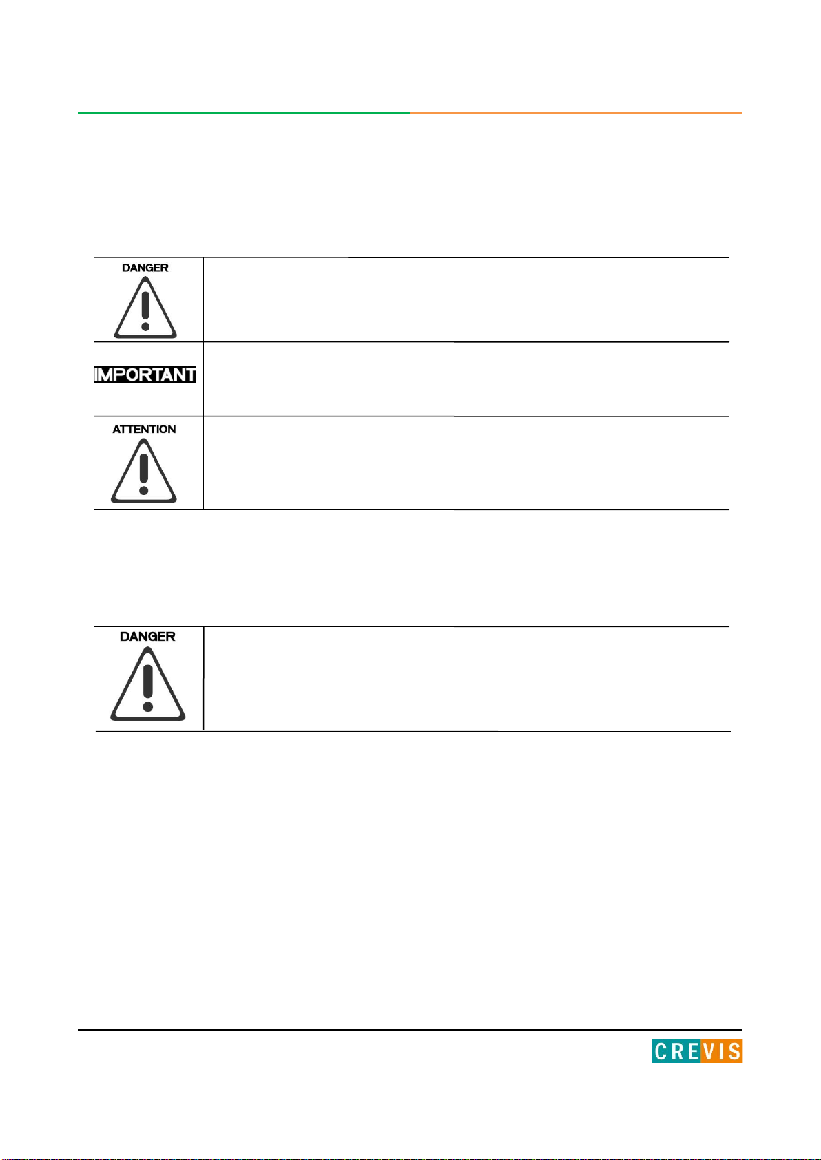
1.1.1. Symbols
Identifies information about practices or circumstances that can cause an explosion
in a hazardous environment, which may lead to personal injury or death property
damage or economic loss.
Identifies information that is critical for successful application and understanding of
the product.
Identifies information about practices or circumstances that can lead to personal
injury, property damage, or economic loss.
Attentions help you to identity a hazard, avoid a hazard, and recognize
the consequences.
1.1.2. Safety Notes
The modules are equipped with electronic components that may be destroyed by
electrostatic discharge. When handling the modules, ensure that the environment
(persons, workplace and packing) is well grounded. Avoid touching conductive
components, e.g. G-BUS Pin.
1.1.3. Certification
c-UL-us UL Listed Industrial Control Equipment, certified for U.S. and Canada
See UL File E235505
FCC, Reach, RoHS- II, China RoHS
CE Certificate
EN 61000-6-2; Industrial Immunity
EN 61000-6-4; Industrial Emissions
7FnIO PROFIBUS Adapter GN-9222 FnIO G-Series
Copyright(C) CREVIS Co.,Ltd Support +82-31-273-6453 URL : www.crevis.co.kr
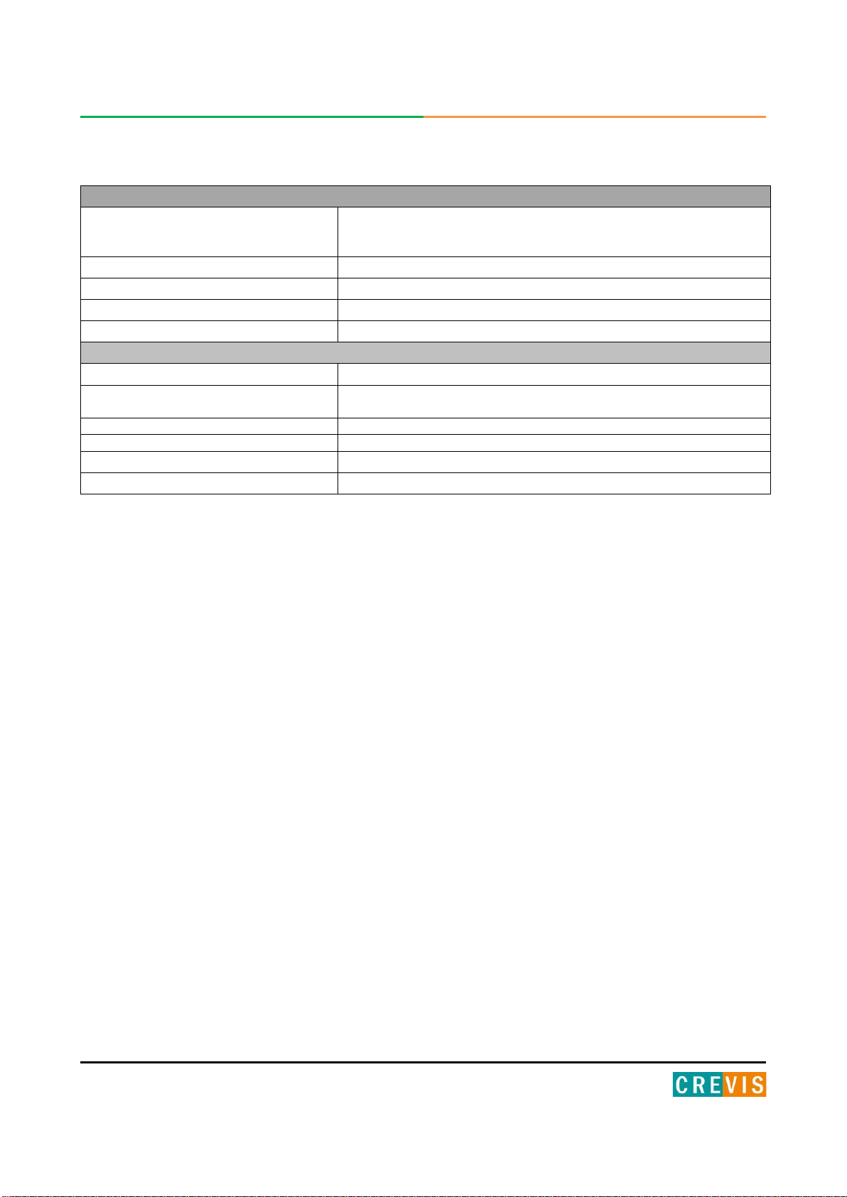
2. Environment Specification
Environment Specification
Operating Temperature
60℃~ 70℃: Power dissipation is limited to 0.8A
-40℃~ 60℃: 1.5A full load is allowed
UL Temperature
-20℃~60℃
Storage Temperature
-40℃~85℃
Relative Humidity
5% ~ 90% non-condensing
Mounting
DIN rail
General Specification
Shock Operating
IEC 60068-2-27
Vibration resistance
Based on IEC 60068-2-6
DNVGN-CCG-0039 : Vibration Class B, 4g
Industrial Emissions
EN 61000-6-4/ALL : 2011
Industrial Immunity
EN 61000-6-2 : 2005
Installation Position
Vertical and horizontal installation is available.
Product Certifications
CE, UL, FCC

8FnIO PROFIBUS Adapter GN-9222 FnIO G-Series
Copyright(C) CREVIS Co.,Ltd Support +82-31-273-6453 URL : www.crevis.co.kr
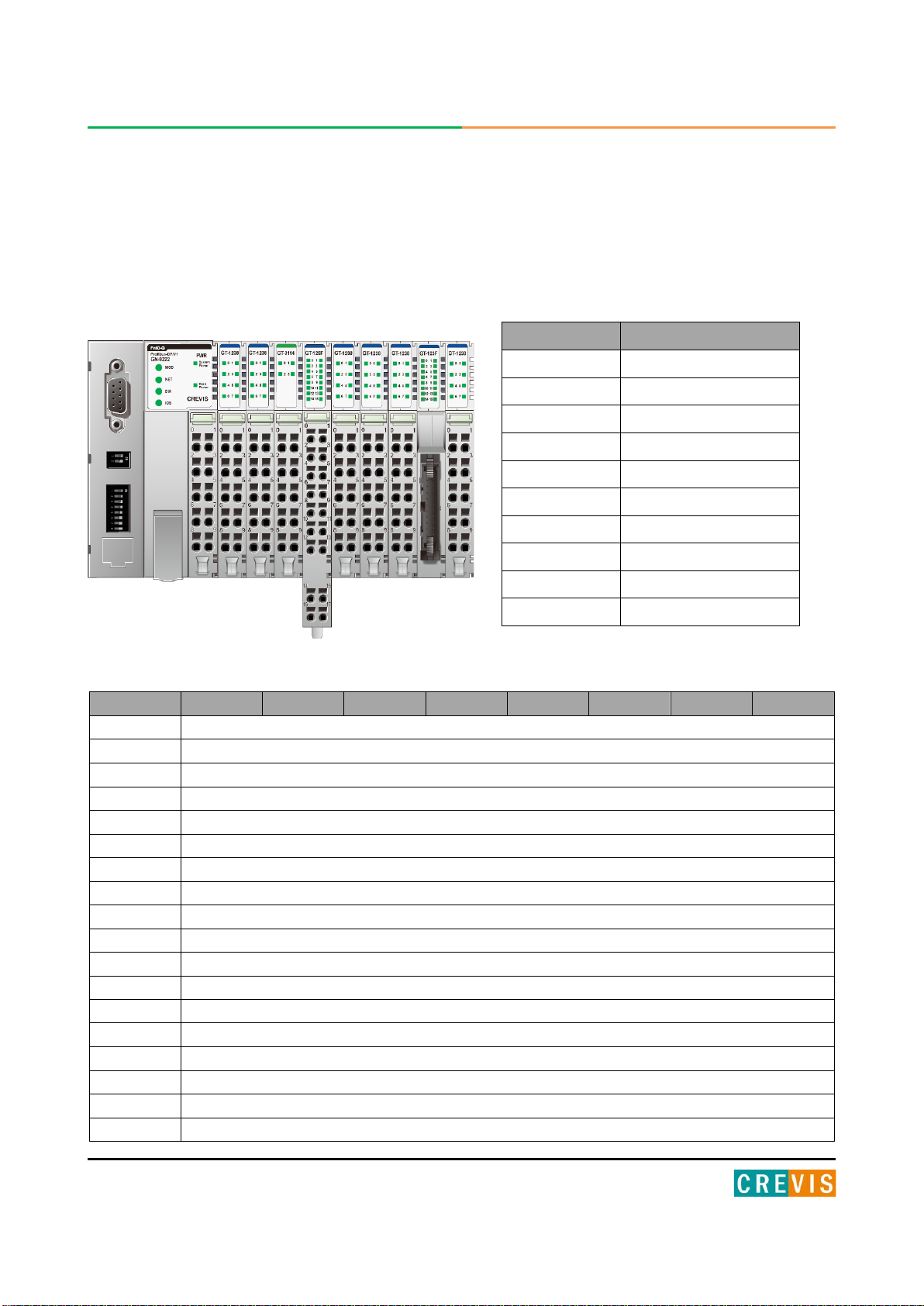
3. GN-9222 (PROFIBUS Network Adapter)
3.1. GN-9222 Specification
Interface Specification, GN-9222
Communication Interface Specification
Redundancy
Not supported
Repeater Control Signal
RS-485 Signal
Freeze mode
Support
Sync mode
Support
Auto baudrate
Support
Fail safe mode
Support
Station type
Slave
FMS support
Not supported
Max. Network Node
125 Nodes
Max. Expansion Slot
63 Slots
I/O Data Size
Input : 244bytes / Output : 244bytes
Indicators
6 Status LEDs
1 Green/Red, Module Status (MOD)
1 Green/Red, Network Status (NET)
1 Red, Diagnostic Status (DIA)
1 Green/Red Expansion I/O Module Status (IOS)
1 Green, System Power Status
1 Green, Field Power Status
Communication Rate
9.6K~12M(1.2Km~100m)
Communication Speed
9.6 ~12000Kbps (Auto baudrate selection)
Bus Connection
9 Pin D-Sub Connector
Other Serial Port
RS232 for MODBUS/RTU, Touch Panel or IOGuide
Serial Configuration (RS232)
Node : 1 (Fixed)
Baud Rate : 115200 (Fixed)
Data bit : 8 (Fixed)
Parity bit : No parity (Fixed)
Stop bit : 1 (Fixed)
Module Location
Starter module left side of G-Series System
Field Power Detection
About 14Vdc
General Specification
UL System Power
Supply voltage : 24Vdc Nominal, Class 2
System Power
Supply voltage : 24Vdc nominal
Supply voltage range : 16~30Vdc
Protection : Output current limit (Min. 1.5A)
Reverse polarity protection
Power Dissipation
100mA @24Vdc
Current for I/O Module
1.5A @5Vdc

9FnIO PROFIBUS Adapter GN-9222 FnIO G-Series
Copyright(C) CREVIS Co.,Ltd Support +82-31-273-6453 URL : www.crevis.co.kr
* Operating temperature
-. -40 ~ 70 temperature range specification can be guaranteed℃under the follwing conditions.
-. Current for I/O Modules : 0.8A below.
-. Otherwise, temperature specification can be guranteed with -40 ~ 60℃.
Isolation
System power to internal logic : Non-Isolation
System power I/O driver : Isolation
UL Field Power
Supply voltage : 24Vdc nominal, Class 2
Field Power
Supply voltage : 24Vdc typical (Max.30Vdc)
Field Power range is defferent depending on IO module series.
Refer to IO module’s specification.
Max. Current Field Power Contact
DC 10A Max.
Wiring
I/O Cable Max. 2.0mm²(AWG 14)
Torque
0.8Nm(7 lb-in)
Weight
163g
Module Size
54mm x 99mm x 70mm
Environment Condition
Refer to ‘Environment Specification’
10 FnIO PROFIBUS Adapter GN-9222 FnIO G-Series
Copyright(C) CREVIS Co.,Ltd Support +82-31-273-6453 URL : www.crevis.co.kr
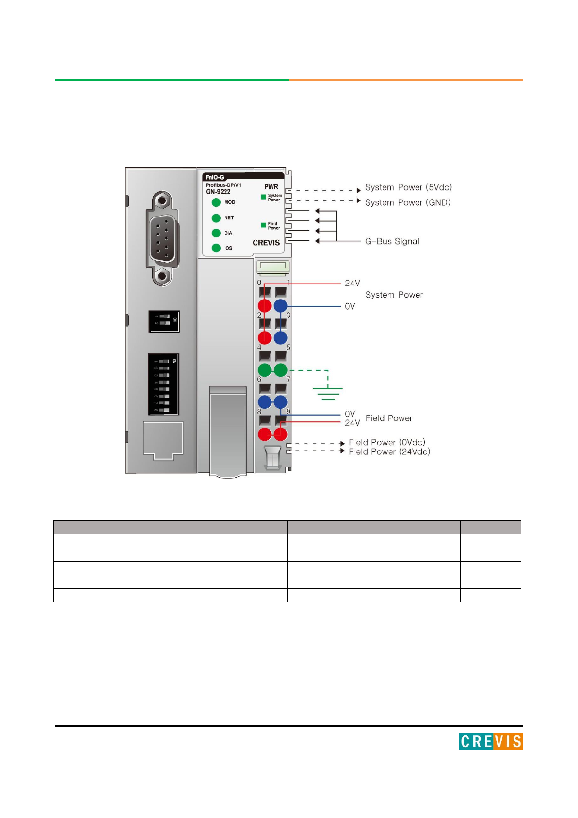
3.2. GN-9222 Wiring Diagram
Pin No.
Signal Description
Signal Description
Pin No.
0
System Power, 24V
System Power, Ground
1
2
System Power, 24V
System Power, Ground
3
4
F.G
F.G
5
6
Field Power, Ground
Field Power, Ground
7
8
Field Power, 24V
Field Power, 24V
9

11 FnIO PROFIBUS Adapter GN-9222 FnIO G-Series
Copyright(C) CREVIS Co.,Ltd Support +82-31-273-6453 URL : www.crevis.co.kr
3.3. GN-9222 LED Indicator
3.3.1. LED Indicatior
3.3.2. MOD(Module Status LED)
Status
LED
To indicate
Not Powered
OFF
power is not supplied to the unit.
Normal, Operational
Green
The unit is operating in normal condition.
Device in Standby
Flashing Green
The EEPROM parameter is not initialized yet.
Serial Number is zero value (0x00000000)
Minor Fault
Flashing Red
The unit has occurred recoverable fault in self-testing.
- EEPROM checksum fault.
Unrecoverable Fault
Red
The unit has occurred unrecoverable fault in self-testing.
- Firmware fault
3.3.3. NET(Network Status LED)
LED No.
LED Function / Description
LED Color
MOD
Module Status
Green/Red
NET
Network Status
Green/Red
DIA
Diagnostic Status
Red
IOS
Extension Module Status
Green/Red
System Power
System Power Enable
Green
Field Power
Field Power Enable
Green
State
LED
To indicate
Not Powered
Not On-line
OFF
Device is not on-line or may not be powered
On-line,
Not connected
Flashing
Green
Device is on-line but has no connections in the
established state.
- Not allocated to a master
On-line,
Connected
Green
Device is on-line and allocated to a master
Connection Time-out
Flashing Red
One or more I/O connections are in the time-out state.
Critical Communication Failure
Red
Faild communication

12 FnIO PROFIBUS Adapter GN-9222 FnIO G-Series
Copyright(C) CREVIS Co.,Ltd Support +82-31-273-6453 URL : www.crevis.co.kr
3.3.4. DIA (Diagnostic Status LED)
3.3.5. IOS LED (Expansion Module Status LED)
3.3.6. Field Power, System Power LED (Field Power, System Power Status LED)
Status
LED
To indicate :
Hardware Error
Flashing Red
Device has hardware cheching error.
(with MOD led is red.)
Expansion Module Error
Flashing Red
Device has expansion module error.
(with IOS led is red.)
IO Configuration Error
Flashing Red
Failed to initalize expansion module
- Overflow Input/Output size. (244bytes / 244bytes)
- Overflow Configuration data size. (244bytes / 244bytes)
- Too many expansion module. (Max 63 slot)
- Mismatch vendor code between adapter and expension
module.
State
LED
To indicate
Not Powered
No Expansion Module
OFF
Device has no expansion module or may not be powered.
On-line,
Do not Exchanging I/O
Flashing
Green
I/O Communication is normal but does not exchanging I/O data.
(Passed the expantion module confiration)
Connection,
Run Exchanging I/O
Green
Exchanging I/O data.
Connection Fault during
Exchanging I/O
Red
One or more expansion module occurred in fault state.
- Changed expansion module configuration.
- Communication failure.
Expansion Configuration
Failed
Flashing
Red
Failed to initialize expansion module.
- Detect invalid expansion module ID.
- Overflow Input/Outeput size. (244bytes/ 244bytes)
- Too many expansion module.
- Initial protocol failure.
- Mismatch vendor code between adapter and expansion
module.
State
LED
To indicate
Not supplied field, system power
OFF
Not supplied 24Vdc field power, 5Vdc system poser.
Supplied field, system power
Green
Supplied 24Vdc field power, 5Vdc system power.
13 FnIO PROFIBUS Adapter GN-9222 FnIO G-Series
Copyright(C) CREVIS Co.,Ltd Support +82-31-273-6453 URL : www.crevis.co.kr
3.4. GN-9222 Electrical Interface
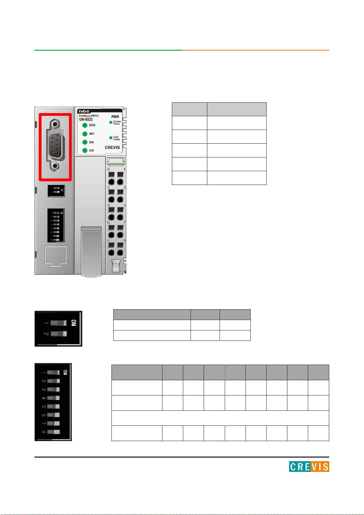
3.4.1. PROFIBUS Connector
3.4.2. Dip Switch
Pin No.
Description
3
RxD / TxD-P
4
CNTR-P
5
DGND
6
VP
8
RXD / TxdD-N
Terminating Resistance
1
2
Applied
On
On
Not applied
Off
Off
Node ID
1
2
3
4
5
6
7
8
1
On
Off
Off
Off
Off
Off
Off
Off
2
Off
On
Off
Off
Off
Off
Off
Off
~
125
On
Off
On
On
On
On
On
Off

14 FnIO PROFIBUS Adapter GN-9222 FnIO G-Series
Copyright(C) CREVIS Co.,Ltd Support +82-31-273-6453 URL : www.crevis.co.kr
3.4.3. RS232 Port for MODBUS/RTU, Touch Panel or IOGuide
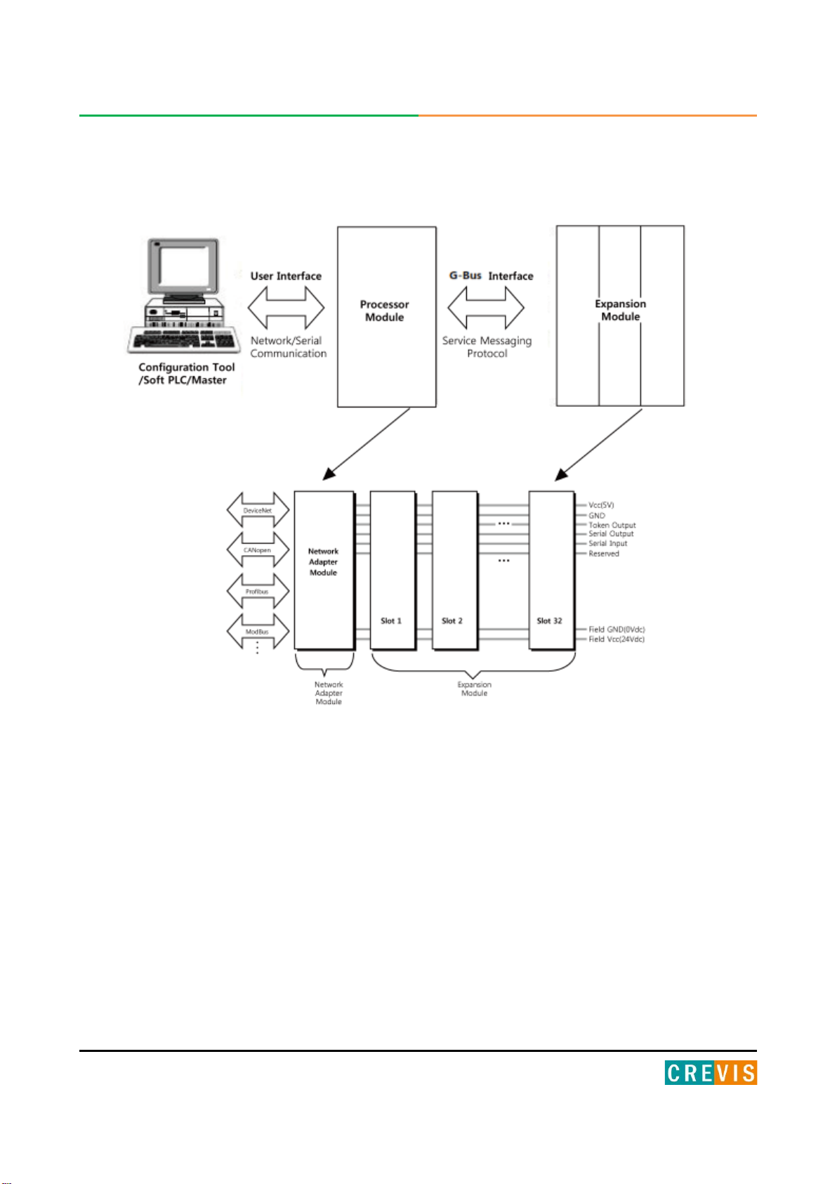
3.5. I/O Process Image Map
An expansion module may have 3 types of data as I/O data, configuration parameter and memory register.
The data exchange between network adapter and expansion modules is done via an I/O process image data
by G-Series Internal Bus protocol. The following figure shows the data flow of process image between
network adapter and expansion modules.
Pin#
Signal Name
Description
1
Reserved
----
2
TXD
RS232 TXD
3
RXD
RS232 RXD
4
GND
RS232 GND
15 FnIO PROFIBUS Adapter GN-9222 FnIO G-Series
Copyright(C) CREVIS Co.,Ltd Support +82-31-273-6453 URL : www.crevis.co.kr
3.5.1. Example of Input Process Image (Input Register) Map
Input image data depends on slot position and expansion slot data type. Input process image data is only
ordered by expansion slot position.
• For example slot configuration
• Input Process Image
Solt Address
Module Description
#0
PROFIBUS Adapter
#1
8-discrete input
#2
8-discrete input
#3
4-analog input
#4
16-discrete input
#5
8-discrete input
#6
8-discrete input
#7
8-discrete input
#8
16-discrete input
#9
8-discrete input
Byte
Bit 7
Bit 6
Bit 5
Bit 4
Bit 3
Bit 2
Bit 1
Bit 0
0
Discrete Input 8 pts (Slot#1)
1
Discrete Input 8 pts (Slot#2)
2
Analog Input Ch0 low byte (Slot#3)
3
Analog Input Ch0 high byte (Slot#3)
4
Analog Input Ch1 low byte (Slot#3)
5
Analog Input Ch1 high byte (Slot#3)
6
Analog Input Ch2 low byte (Slot#3)
7
Analog Input Ch2 high byte (Slot#3)
8
Analog Input Ch3 low byte (Slot#3)
9
Analog Input Ch3 high byte (Slot#3)
10
Discrete Input 8 pts (Slot#4)
11
Discrete Input 8 pts (Slot#4)
12
Discrete Input 8 pts (Slot#5)
13
Discrete Input 8 pts (Slot#6)
14
Discrete Input 8 pts (Slot#7)
15
Discrete Input 8 pts (Slot#8)
16
Discrete Input 8 pts (Slot#8)
17
Discrete Input 8 pts (Slot#9)

16 FnIO PROFIBUS Adapter GN-9222 FnIO G-Series
Copyright(C) CREVIS Co.,Ltd Support +82-31-273-6453 URL : www.crevis.co.kr
3.5.2. Example of Output Process Image (Output Register) Map
Output image data depends on slot position and expansion slot data type. Output process image data is only
ordered by expansion slot position.
• For example slot configuration
Output Process Image Mode#0 (Uncompressed Input Processing Data), default output image
Byte
Bit 7
Bit 6
Bit 5
Bit 4
Bit 3
Bit 2
Bit 1
Bit 0
0
Discrete Output 8 pts(Slot#1)
1
Discrete Output 8 pts(Slot#2)
2
Analog Output Ch0 low byte(Slot#3)
3
Analog Output Ch0 high byte(Slot#3)
4
Analog Output Ch1 low byte(Slot#3)
5
Analog Output Ch1 high byte(Slot#3)
6
Analog Output Ch2 low byte(Slot#3)
7
Analog Output Ch2 high byte(Slot#3)
8
Analog Output Ch3 low byte(Slot#3)
9
Analog Output Ch3 high byte(Slot#3)
10
Discrete Output low 4 pts(Slot#4)
12
Discrete Output low 4 pts(Slot#5)
13
Discrete Output low 8 pts(Slot#6)
14
Discrete Output low 8 pts(Slot#7)
15
Analog Output Ch0 low byte(Slot#8)
16
Analog Output Ch0 high byte(Slot#8)
17
Analog Output Ch1 low byte(Slot#8)
18
Analog Output Ch1 high byte(Slot#8)
19
Analog Output Ch2 low byte(Slot#8)
20
Analog Output Ch2 high byte(Slot#8)
21
Analog Output Ch3 low byte(Slot#8)
22
Analog Output Ch3 high byte(Slot#8)
24
Discrete output low 8 pts(Slot#9)
25
Discrete output low 8 pts(Slot#10)
26
Discrete output low 8 pts(Slot#10)
Slot Address
Module Description
#0
PROFIBUS Adapter
#1
8-discrete output
#2
8-discrete output
#3
4-analog output
#4
4-relay output
#5
4-relay output
#6
8-discrete output
#7
8-discrete output
#8
4-analog output
#9
4-relay output
#10
16-discrete output

17 FnIO PROFIBUS Adapter GN-9222 FnIO G-Series
Copyright(C) CREVIS Co.,Ltd Support +82-31-273-6453 URL : www.crevis.co.kr
4. Dimension
4.1. GN-9222
(mm)
18 FnIO PROFIBUS Adapter GN-9222 FnIO G-Series
Copyright(C) CREVIS Co.,Ltd Support +82-31-273-6453 URL : www.crevis.co.kr
5. Mechanical Set Up
5.1. Total Expansion
The number of the module assembly that can be connected is 63. So the maximum length is 426mm
Exception.
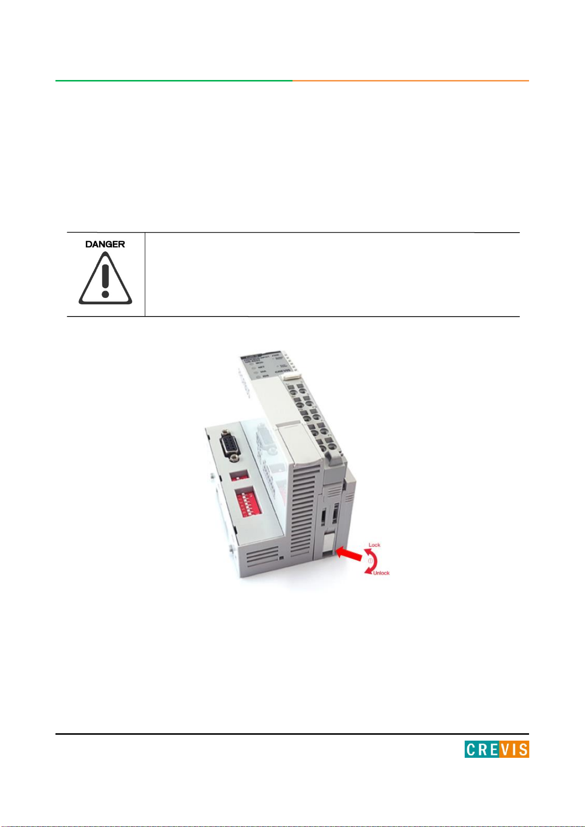
5.2. Plugging and Removal of the Components.
Before work is done on the components, the voltage supply must be
turned off.
As above figure in order to safeguard the FnIO module from jamming, it should be fixed onto the DIN rail
with locking level. To do so, fold on the upper of the locking lever.
To pull out the FnIO module, unfold the locking lever as below figure.

19 FnIO PROFIBUS Adapter GN-9222 FnIO G-Series
Copyright(C) CREVIS Co.,Ltd Support +82-31-273-6453 URL : www.crevis.co.kr
5.3. Internal G-Bus/Field Power Contacts
Communication between the NA series and the expansion module as well as system / field power
supply of the bus modules is carried out via the internal bus. It is comprised of 6 data pin and 2 field
power pin.
Do not touch data and field power pins in order to avoid soiling and damage by ESD
noise.
20 FnIO PROFIBUS Adapter GN-9222 FnIO G-Series
Copyright(C) CREVIS Co.,Ltd Support +82-31-273-6453 URL : www.crevis.co.kr
6.PROFIBUS Electrical Interface
6.1. G-Bus System
•Network Adapter Module
The Network Adapter Module forms the link between the field bus and the field devices with the
Expansion Modules.
The connection to different field bus systems can be established by each of the corresponding
Network Adapter Module, e.g. for SyncNet, PROFIBUS, CANopen, DeviceNet , Ethernet/IP, CC-Link,
MODBUS/Serial, MODBUS/TCP etc.
•Expansion Module
The Expansion Modules are supported a variety of input and output field devices.
There are digital and analog input/output modules and special function modules.
Table of contents
Other CREVIS Adapter manuals


Popular Adapter manuals by other brands


IOGear
IOGear GKMB01 user manual

Panasonic
Panasonic CA-PANSC1U quick start guide

TRENDnet
TRENDnet TEG-PCBUSR Quick installation guide

Encore
Encore ENUBT-C1 Specifications

ZyXEL Communications
ZyXEL Communications NWD2205 quick start guide

Mobility Electronics
Mobility Electronics INVISION PS6U1UPE user guide

TIME MARK
TIME MARK DRA-1 quick start guide

Desoutter
Desoutter CVI2 manual

Poly
Poly Polycom OBi302 Installation and configuration guide

ATTO Technology
ATTO Technology Celerity FC-21PS Specification sheet

OSS
OSS OSS-CPCIe3-3U-10GbE-x4-QUAD installation guide

D-Link
D-Link AirPlus G DWL-G510 Quick installaion guide