CREVIS FnIO SSeries User manual

1FnIO PROFINET Adapter NA-9187 FnIO S-Series
Copyright(C) CREVIS Co.,Ltd Support +82-31-899-4599 URL : www.crevis.co.kr
Version 1.06
2013 CREVIS Co.,Ltd
NA-9187
User Manual
PROFINET Adapter

2FnIO PROFINET Adapter NA-9187 FnIO S-Series
Copyright(C) CREVIS Co.,Ltd Support +82-31-899-4599 URL : www.crevis.co.kr
DOCUMENT CHANGE SUMMARY
REV
PAGE
REMARKS
DATE
EDITOR
1.0
New
Document
2011/10/21
JE Kang
1.01
5
6
17
Add your experience
Changed Certification
Add to Cable
2012/1/13
JE Kang
1.02
Add Example GSDML setting
Changed 6.2. and Trouble shooting, LED
2012/2/13
JE Kang
Changed Cover
2012/2/28
JE Kang
1.03
Changed Crevis TEL
2013/4/4
JE Kang
1.04
8
Changed Storage Temperature (-25℃-40℃)
2013/6/3
JE Kang
1.05
Environment Spec. 50℃→55℃(UL Temp)
2013/7/3
JE Kang
1.06
Modify the Pin Description
2014/05/08
YMKIM

3FnIO PROFINET Adapter NA-9187 FnIO S-Series
Copyright(C) CREVIS Co.,Ltd Support +82-31-899-4599 URL : www.crevis.co.kr
CONTENTS
1. Important Notes ......................................................................................................................................................... 6
1.1. Safety Instruction ...................................................................................................................................... 7
1.1.1. Symbols......................................................................................................................................................... 7
1.1.2. Safety Notes................................................................................................................................................ 7
1.1.3. Certification ................................................................................................................................................. 7
2. Specification.................................................................................................................................................................. 8
2.1. The Interface ............................................................................................................................................... 8
2.1.1. NA-9187........................................................................................................................................................ 8
2.2. Specification ................................................................................................................................................ 9
2.2.1. General Specification............................................................................................................................... 9
2.2.2. Interface Specification...........................................................................................................................10
2.3. LED Indicator.............................................................................................................................................11
2.3.1. Module Status LED (MOD) .................................................................................................................11
2.3.2. Network Status LED (NET) ..................................................................................................................11
2.3.3. Expansion Module Status LED (I/O) ...............................................................................................12
2.3.4. Field Power Status LED ........................................................................................................................12
2.3.5. Port1, Port2 : Link and Activity.........................................................................................................12
3. Dimension....................................................................................................................................................................13
3.1. NA-9187......................................................................................................................................................13
4. Mechanical Set Up...................................................................................................................................................14
4.1. Total Expansion........................................................................................................................................14
4.2. Plugging and Removal of the Components...............................................................................14

4FnIO PROFINET Adapter NA-9187 FnIO S-Series
Copyright(C) CREVIS Co.,Ltd Support +82-31-899-4599 URL : www.crevis.co.kr
5. PROFINET Electrical Interface..............................................................................................................................15
5.1. FnBus System............................................................................................................................................15
5.2. FnBus Pin Description...........................................................................................................................17
5.3. PROFINET Electrical Interface ............................................................................................................18
5.3.1. NA-9187......................................................................................................................................................18
5.3.2. PROFINET Parameterization by Rotary Switch ..........................................................................19
5.3.3. I/O Process Image Map .......................................................................................................................21
5.4. Example Configuration with SEIMENS PLC STEP7...................................................................22
5.4.1. Example GSDML Setting......................................................................................................................22
5.4.2. Example Assign the device name....................................................................................................24
5.4.3. Example Editing Ethernet Nodes(in non-volatile memory) .................................................26
5.4.4. Parameters, IO cycle time and port option with STEP7........................................................29
6. NA-9187 PROFINET.................................................................................................................................................33
6.1. NA-9187 Parameter ...............................................................................................................................33
6.2. NA-9187 PROFINET IO Characteristics..........................................................................................34
6.2.1. Device identity..........................................................................................................................................34
6.2.2. Device Access Point...............................................................................................................................34
6.2.3. Sub-slot of NA-9187 .............................................................................................................................35
7. Trouble Shooting......................................................................................................................................................36
7.1. How to diagnose by LED indicator.................................................................................................36
7.2. How to diagnose when device couldn’t communicate network.......................................37
APPENDIX A.........................................................................................................................................................................38
A.1. Product List.............................................................................................................................................................38


6FnIO PROFINET Adapter NA-9187 FnIO S-Series
Copyright(C) CREVIS Co.,Ltd Support +82-31-899-4599 URL : www.crevis.co.kr
1.Important Notes
Solid state equipment has operational characteristics differing from those of electromechanical equipment.
Safety Guidelines for the Application, Installation and Maintenance of Solid State Controls describes some important
differences between solid state equipment and hard-wired electromechanical devices.
Because of this difference, and also because of the wide variety of uses for solid state equipment, all persons
responsible for applying this equipment must satisfy themselves that each intended application of this equipment is
acceptable.
In no event will CREVIS be responsible or liable for indirect or consequential damages resulting from the use or
application of this equipment.
The examples and diagrams in this manual are included solely for illustrative purposes. Because of the many variables
and requirements associated with any particular installation, CREVIS cannot assume responsibility or liability for actual
use based on the examples and diagrams.
If you don’t follow the directions, it could cause a personal injury, damage to the equipment or explosion
Do not assemble the products and wire with power applied to the system. Else it may cause an electric arc, which
can result into unexpected and potentially dangerous action by field devices. Arching is explosion risk in
hazardous locations. Be sure that the area is non-hazardous or remove system power appropriately before
assembling or wiring the modules.
Do not touch any terminal blocks or IO modules when system is running. Else it may cause the unit to an electric
shock or malfunction.
Keep away from the strange metallic materials not related to the unit and wiring works should be controlled by the
electric expert engineer. Else it may cause the unit to a fire, electric shock or malfunction.
If you disobey the instructions, there may be possibility of personal injury, damage to equipment or
explosion. Please follow below Instructions.
Check the rated voltage and terminal array before wiring. Avoid the circumstances over 55℃of temperature.
Avoid placing it directly in the sunlight.
Avoid the place under circumstances over 85% of humidity.
Do not place Modules near by the inflammable material. Else it may cause a fire.
Do not permit any vibration approaching it directly.
Go through module specification carefully, ensure inputs, output connections are made with the specifications. Use
standard cables for wiring.
Use Product under pollution degree 2 environment..
Warning!
Caution!
7FnIO PROFINET Adapter NA-9187 FnIO S-Series
Copyright(C) CREVIS Co.,Ltd Support +82-31-899-4599 URL : www.crevis.co.kr
1.1. Safety Instruction
1.1.1. Symbols
Identifies information about practices or circumstances that can cause an explosion in a
hazardous environment, which may lead to personal injury or death property damage or
economic loss.
Identifies information that is critical for successful application and understanding of the
Product.
Identifies information about practices or circumstances that can lead to personal
injury, property damage, or economic loss.
Attentions help you to identity a hazard, avoid a hazard, and recognize the consequences.
1.1.2. Safety Notes
The modules are equipped with electronic components that may be destroyed by electrostatic
discharge. When handling the modules, ensure that the environment (persons, workplace and
packing) is well grounded. Avoid touching conductive components, e.g. FnBUS Pin.
1.1.3. Certification
c-UL-us UL Listed Industrial Control Equipment, certified for U.S. and Canada
See UL File E235505
CE Certificate
EN 61000-6-2; Industrial Immunity
EN 61000-6-4; Industrial Emissions
FCC
8FnIO PROFINET Adapter NA-9187 FnIO S-Series
Copyright(C) CREVIS Co.,Ltd Support +82-31-899-4599 URL : www.crevis.co.kr
2.Specification
2.1. The Interface
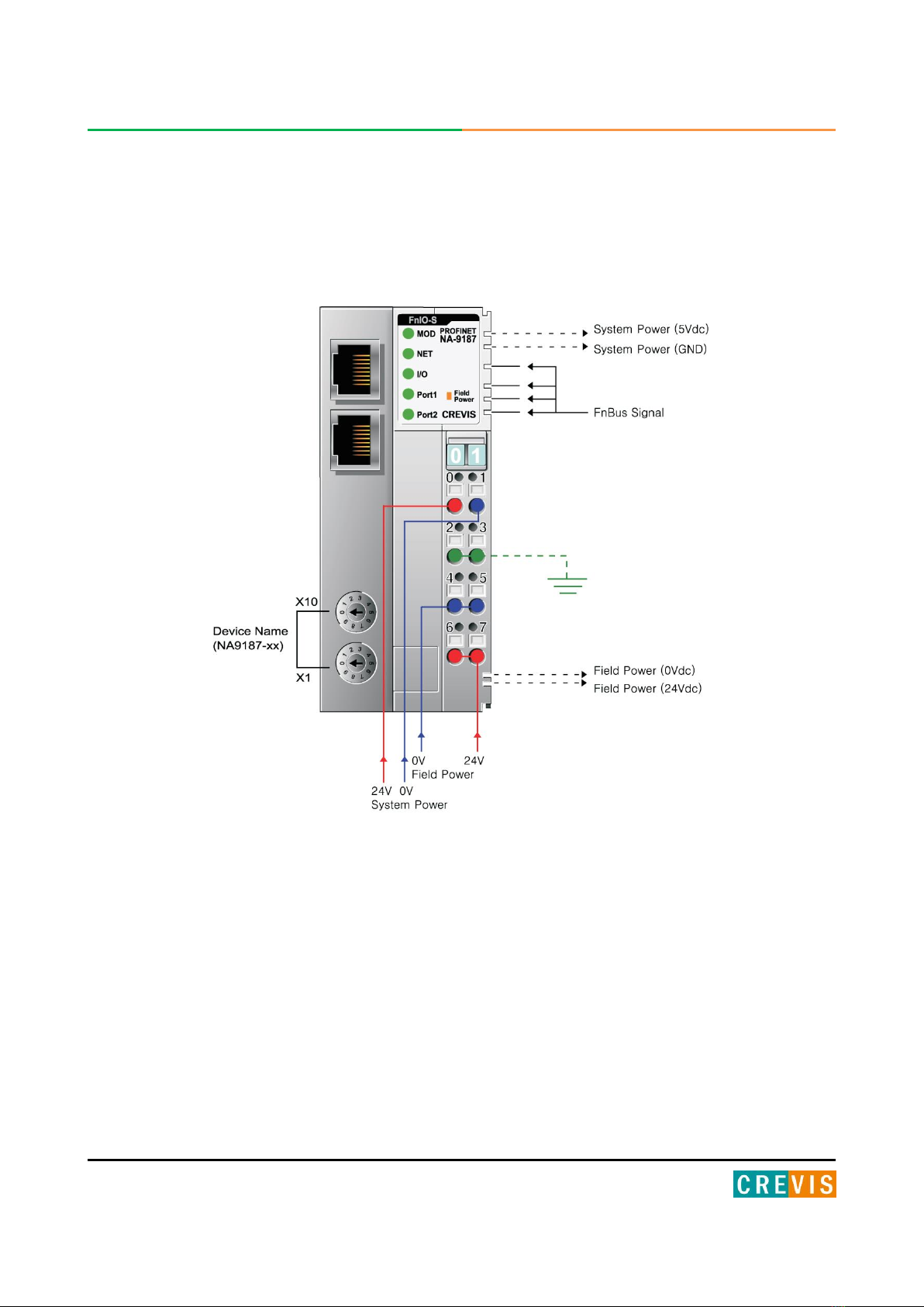
2.1.1. NA-9187

9FnIO PROFINET Adapter NA-9187 FnIO S-Series
Copyright(C) CREVIS Co.,Ltd Support +82-31-899-4599 URL : www.crevis.co.kr
2.2. Specification
2.2.1. General Specification
General Specification
System Power
Supply voltage : 24Vdc nominal
Supply voltage range : 11~28.8Vdc
Protection : Output current limit (Min. 1.5A)
Reverse polarity protection
Power Dissipation
115mA typical @24Vdc
Current for I/O Module
1.5A @5Vdc
Isolation
System power to internal logic : Non-isolation
System power to I/O driver : Isolation
Field Power
Supply voltage : 24Vdc nominal
Supply voltage range : 11~28.8Vdc
Current in Jumper Contacts
DC 10A Max.
Weight
150g
Module Size
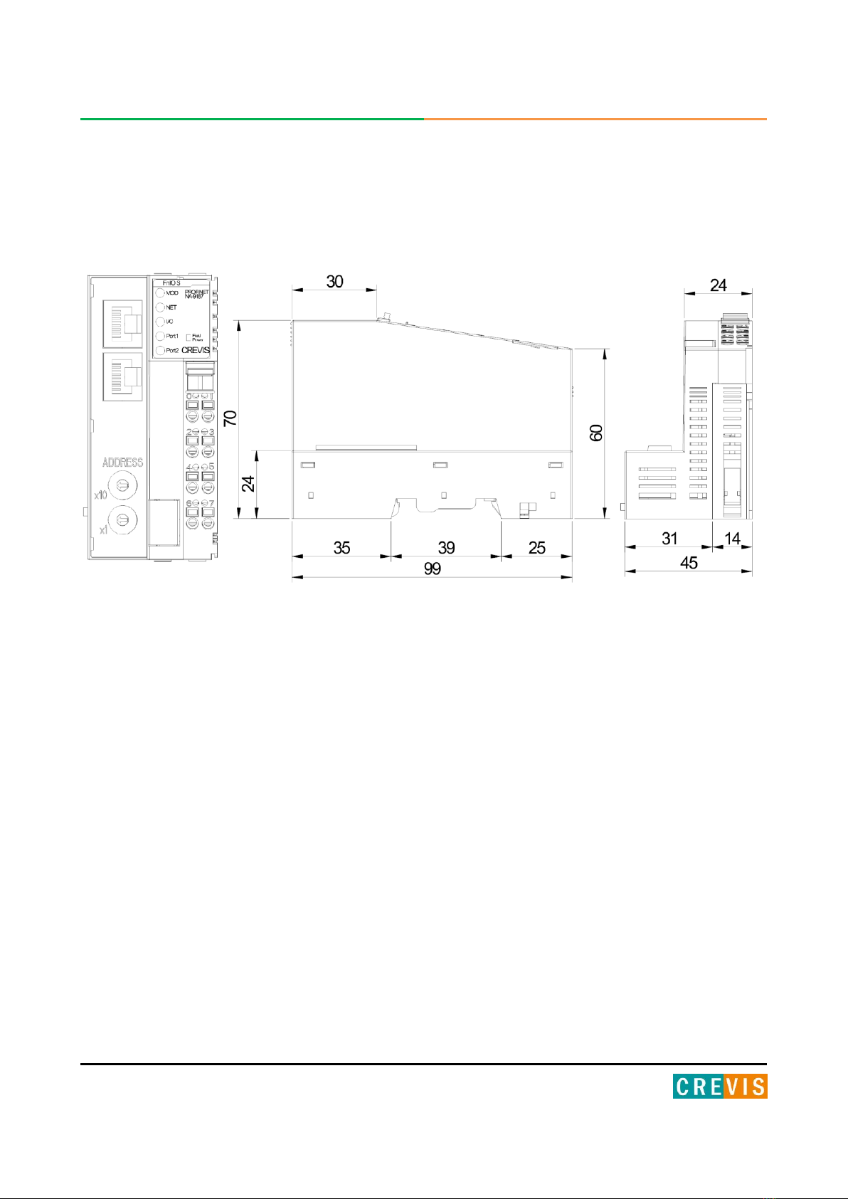
45mm x 99mm x 70mm
Environment Condition
Refer to Environment Specification
Environmental Specifications
Surrounding Temperature
0 to 55℃
Operating Temperature
0 to 55℃
Storage Temperature
-40℃to 85℃
Relative Humidity
90% non-condensing
Protection Class
IP 20
Mounting
DIN rail

10 FnIO PROFINET Adapter NA-9187 FnIO S-Series
Copyright(C) CREVIS Co.,Ltd Support +82-31-899-4599 URL : www.crevis.co.kr
2.2.2. Interface Specification
Interface Specification, NA-9187
Protocol
PROFINET I/O RT, DCP, SNMP, LLDP
Station Type
PROFINET IO Device
Topology
Line or Star topology
Number of Nodes
Limited by the IP address
Number of Expansion I/O slots
Max. 32 slots
I/O Data Size
252 Bytes inputs/252 Bytes outputs
Indicators
1 green/red MOD Status Indicator
1 green/red NET Status Indicator
1 green/red I/O Status Indicator
1 green Port1 Link/Active Status Indicator
1 green Port2 Link/Active Status Indicator
1 green Field Power Status indicator
Baud rate
100Mbps Full-Duplex
Module Location
Starter module - Left side of FnIO System

11 FnIO PROFINET Adapter NA-9187 FnIO S-Series
Copyright(C) CREVIS Co.,Ltd Support +82-31-899-4599 URL : www.crevis.co.kr
2.3. LED Indicator
2.3.1. Module Status LED (MOD)
State
LED is :
To indicate :
No Power
Off
No power is supplied to the unit.
OS Handle Error
Flashing Green
0.2s
OS handle unexpected exceptions.
Wrong IP address
Flashing Green 1s
IP address is 0.0.0.0
Device Operational
Green
The unit is operating in normal condition.
OS Fatal Error
Flashing Red 0.2s
OS Fatal error is occurred
Invalid RAM Image
Flashing Red 1s
Invalid RAM Image
User fatal error
Red
Invalid boot image header(Flash), ROM Boot loader
2.3.2. Network Status LED (NET)
State
LED is :
To indicate :
Not Powered
Not On-line
Off
Device is not on-line or may not be powered
On-line,
Not connected
Flashing Green
0.2s
PROFINET IO connection has been established.
Wait parameters.
Data Exchange Stop
Flashing Green 1s
PROFINET IO data exchange stop
On-line,
Connected
Green
Device is on-line and allocated to a master
Invalid Configuration
Flashing Red 0.2s
Invalid Configuration
Minor Fault
Flashing Red 1s
PROFINET IO Connection is aborted after Data exchange
Fault
RED
PROFINET IO connection is aborted before a data exchange

12 FnIO PROFINET Adapter NA-9187 FnIO S-Series
Copyright(C) CREVIS Co.,Ltd Support +82-31-899-4599 URL : www.crevis.co.kr
2.3.3. Expansion Module Status LED (I/O)
2.3.4. Field Power Status LED
2.3.5. Port1, Port2 : Link and Activity
State
LED is :
To indicate :
Not Powered
No Expansion Module
Off
Device has no expansion module or may not be powered
Fn-Bus On-line,
Do not Exchanging I/O
Flashing Green
Fn-Bus is on-line but does not exchanging I/O data
- Passed the expansion module configuration.
Fn-Bus Connection,
Run Exchanging IO
Green
Expansion Slot is connected and run exchanging I/O data
FnBus connection fault
during exchanging IO
Red
One or more expansion module occurred in fault state.
- Changed expansion module configuration.
- FnBus communication failure.
- Word data type error
- Parameter setting error
Expansion
Configuration Failed
Flashing Red
Failed to initialize expansion module
- Detected invalid expansion module ID.
- Overflowed Input / Output Size
- Too many expansion module
- Initial protocol failure
- Mismatch vendor code between adapter and expansion module.
State
LED is :
To indicate :
Not Supplied Field
Power
Off
Not supplied 24V dc field power
Supplied Field Power
Green
Supplied 24V dc field power
State
LED is :
To indicate :
Link Down
Off
Link is down
Active
Flashing Green
Active is present
Link UP
Green
Link is up (Physical connection is established)
13 FnIO PROFINET Adapter NA-9187 FnIO S-Series
Copyright(C) CREVIS Co.,Ltd Support +82-31-899-4599 URL : www.crevis.co.kr
3.Dimension
3.1. NA-9187
(mm)
14 FnIO PROFINET Adapter NA-9187 FnIO S-Series
Copyright(C) CREVIS Co.,Ltd Support +82-31-899-4599 URL : www.crevis.co.kr
4.Mechanical Set Up
4.1. Total Expansion
The number of the module assembly that can be connected is 32. So the maximum length is 426mm Exception.
ST-2748 is excepted to calculate maximum length because that is double width module.
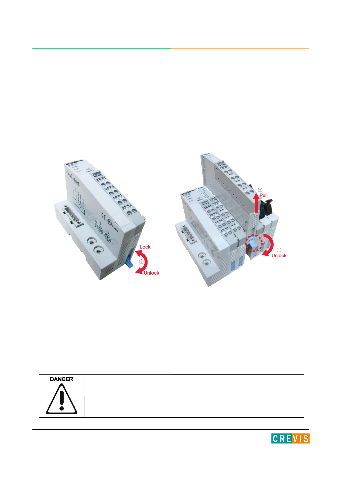
4.2. Plugging and Removal of the Components.
As above figure in order to safeguard the FnIO module from jamming, it should be fixed onto the DIN rail with locking
level. To do so, fold on the upper of the locking lever.
To pull out the FnIO module, unfold the locking lever as below figure.
Before work is done on the components, the voltage supply must be turned
off.

15 FnIO PROFINET Adapter NA-9187 FnIO S-Series
Copyright(C) CREVIS Co.,Ltd Support +82-31-899-4599 URL : www.crevis.co.kr
5.PROFINET Electrical Interface
5.1. FnBus System

16 FnIO PROFINET Adapter NA-9187 FnIO S-Series
Copyright(C) CREVIS Co.,Ltd Support +82-31-899-4599 URL : www.crevis.co.kr
• Network Adapter Module
The Network Adapter Module forms the link between the field bus and the field devices with the Expansion
Modules.
The connection to different field bus systems can be established by each of the corresponding Network Adapter
Module, e.g. for SyncNet, PROFIBUS, CANopen, DeviceNet, Ethernet/IP, CC-Link, MODBUS/Serial,
MODBUS/TCP etc.
• Expansion Module
The Expansion Modules are supported a variety of input and output field devices.
There are digital and analog input/output modules and special function modules.
• Two types of FnBus Message
- Service Messaging
- I/O Messaging
17 FnIO PROFINET Adapter NA-9187 FnIO S-Series
Copyright(C) CREVIS Co.,Ltd Support +82-31-899-4599 URL : www.crevis.co.kr
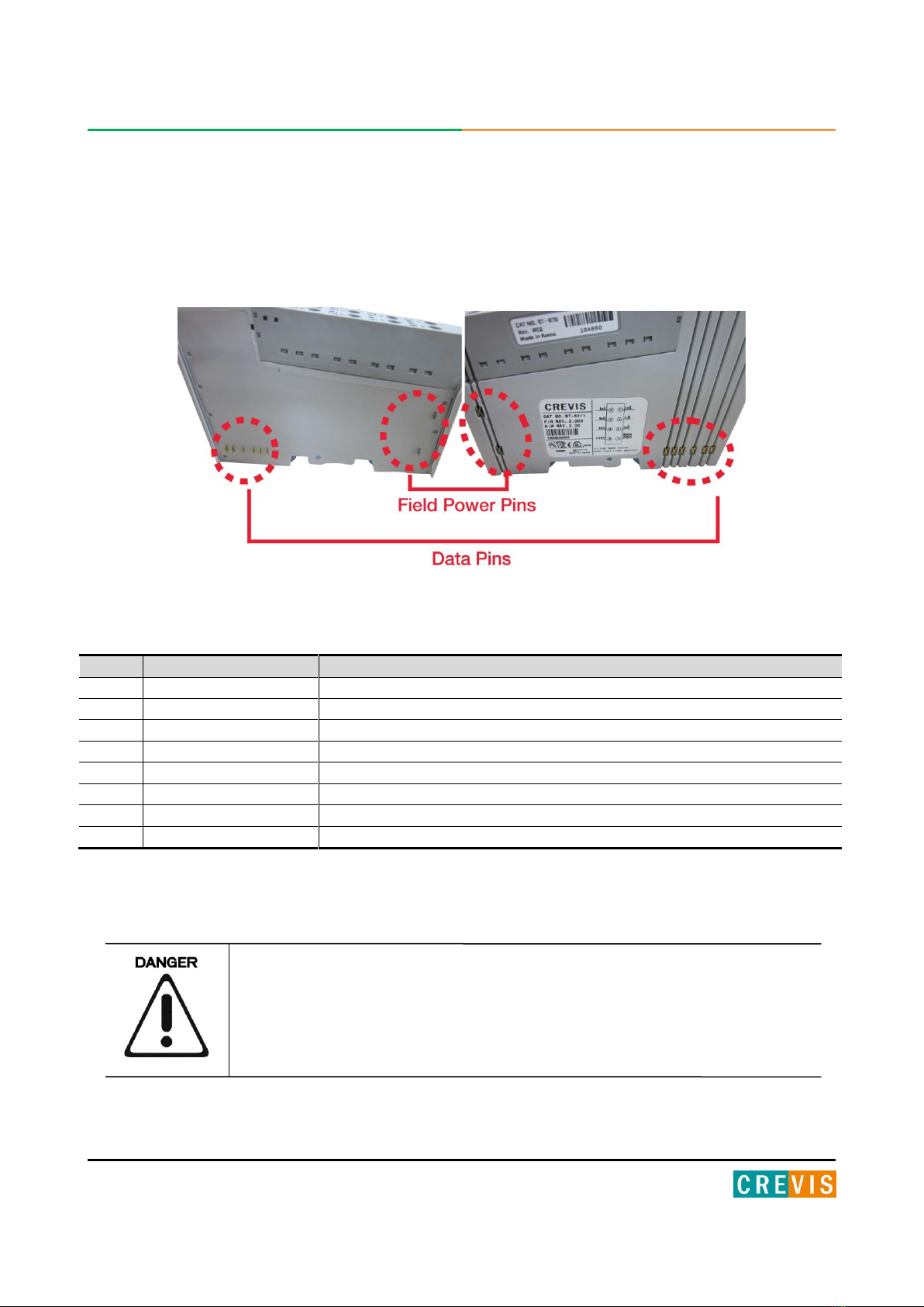
5.2. FnBus Pin Description
Communication between the NA series and the expansion module as well as system / field power supply of the bus
modules is carried out via the internal bus. It is comprised of 6 data pin and 2 field power pin.
Do not touch data and field power pins in order to avoid soiling and damage
by ESD noise.
No.
Name
Description
1
Vcc
System supply voltage (5V dc).
2
GND
System Ground.
3
Token Output
Token output port of Processor module.
4
Serial Output
Transmitter output port of Processor module.
5
Serial Input
Receiver input port of Processor module.
6
Reserved
Reserved for bypass Token.
7
Field GND
Field Ground.
8
Field Vcc
Field supply voltage (24Vdc).

18 FnIO PROFINET Adapter NA-9187 FnIO S-Series
Copyright(C) CREVIS Co.,Ltd Support +82-31-899-4599 URL : www.crevis.co.kr
5.3. PROFINET Electrical Interface
5.3.1. NA-9187
Shielded RJ-45 Socket
Cable : EtherNet Cable
Up to 100m from Ethernet Hub
The use of an incorrect supply voltage or frequency can cause severe damage
to the component.
RJ-45
Signal
Name
Description
1
TD+
Transmit +
2
TD-
Transmit -
3
RD+
Receive +
4
-
5
-
6
RD-
Receive -
7
-
8
-
Case
Shield
Hub
FnIO
FnIO
Upto 100m
Upto 100m
※Caution
- Industrial HUB for EIP recommended
- Cable, the noise cable recommended

19 FnIO PROFINET Adapter NA-9187 FnIO S-Series
Copyright(C) CREVIS Co.,Ltd Support +82-31-899-4599 URL : www.crevis.co.kr
5.3.2. PROFINET Parameterization by Rotary Switch
Value
Description
Factory settings
0
- Name of station will be read from flash memory.
(For example,NA9187-1)
- IP address will be read from flash memory.
- Name of station : NA9187-00
- IP address :192.168.0.254
- Subnet mask : 255.255.255.0
- Gateway : 192.168.0.1
1~99
- Name of station will be NA9187-xx.
(xx is the value of Rotary Switch)
- IP address will be read from flash memory.
When the rotary switch is not set to non-zero (1~99):
If the decimal value of the rotary switch is not zero (0), the name of device will be fixed as
“NA9187-xx” (xx: 1~99). You must put the fixed device name.
X 10 (MSD)
X 1 (LSD)
When the rotary switch is set to zero (0):
If the decimal value of the rotary switch set to zero (0), the device name will be read from nonvolatile memory. You
should put the same name as the name from non-volatile memory. If you want to read the name in non-volatile memory,
please refer to Chapter 3.Editing Ethernet nodes.
NA-1987 Devices on a PROFINET subnet must have unique names. The device names must satisfy DNS naming
conventions. This means that the following rules must be observed:
–Names are limited to a total of 127 characters (letters, numbers, dashes or dots)
–Any component part (that is, a character string between two dots) of the device name may only be up to 63 characters
long.
–Names cannot contain any special characters such as umlauts, parentheses, underscores, forward or backward slashes,
empty spaces, etc. The dash is the only special character allowed.
–Names must not begin or end with the "-" or "." characters.
–Names must not have the format n.n.n.n (where n = 0...999).
–The device name must not start with numbers.
–Names must not begin with the character sequence "port-xyz-" (where x, y, z = 0...9).
–If you want to change the IP address in non-volatile memory, please refer to Chapter3. (Editing Ethernet Nodes)
20 FnIO PROFINET Adapter NA-9187 FnIO S-Series
Copyright(C) CREVIS Co.,Ltd Support +82-31-899-4599 URL : www.crevis.co.kr
Device names are assigned to PROFINET IO device when the device is being set up and placed in operation for the first
time ("commissioned").
The default name is “NA9187-SW”(see "Short Designation").
If several devices of the same type are arranged on the same PROFINET IO system, then STEP7 automatically adds
sequential number to the name from the GSD file. In this case, the second device has the extension "-1", the third one
has the extension "-2", etc.
◆Communication Speed Setting
- See Master Module Setting about communication speed setting.
MAC ID addresses have to be unique throughout the entire interconnected
networks.
Other manuals for FnIO SSeries
3
This manual suits for next models
1
Table of contents
Other CREVIS Adapter manuals


