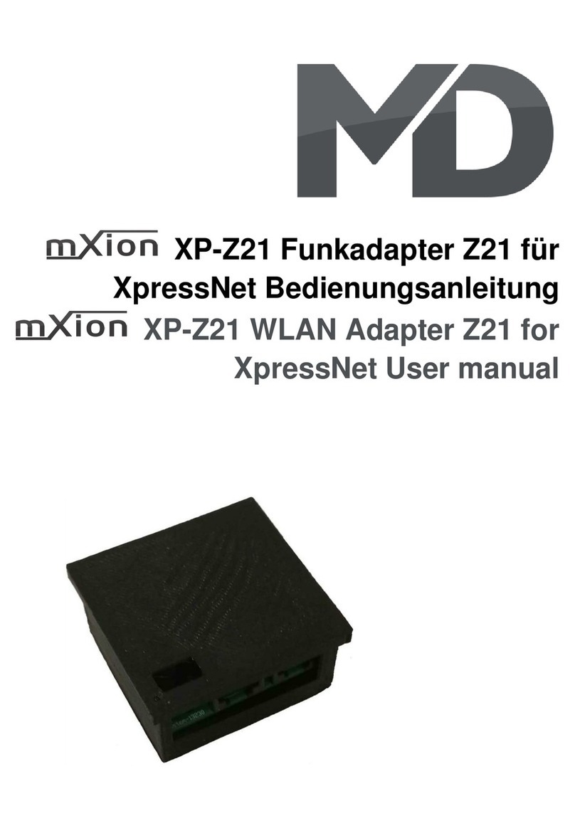
CREVIS M Series User manual

M9287
Specification
Revision 1.01
M-Series ProfiNet
Network Adapter (Sing e Type)
Page 1
Date: 2020. 3. 16
FnIO M - Series:
M9287
M9287 Profinet Network Adapter (Single Type)

M9287
Specification
Revision 1.01
M-Series ProfiNet
Network Adapter (Sing e Type)
Page 2
Tab e of Contents
Tab e of Contents .............................................................................................................................................. 2
History .............................................................................................................................................................. 4
1.ENVIRONMENT SPECIFICATION ............................................................................................................ 5
2.M9287 (PROFINET NETWORK ADAPTER) .............................................................................................. 6
2.1.M9287 Specification ............................................................................................................................... 6
2.2.9287 Wiring Diagram ............................................................................................................................. 7
2.3.M9287 LED Indicator ............................................................................................................................. 8
2.3.1.LED Indicator .................................................................................................................................. 8
2.3.2.MOD (Modu e Status LED) ............................................................................................................. 8
2.3.3.NET (Network Status LED) ............................................................................................................. 8
2.3.4.Error (Exchange Data/Traffic Present LED) .................................................................................... 8
2.3.5.IOS LED (Extension Modu e Status LED) ...................................................................................... 8
2.4.M7001 LED Indicator ............................................................................................................................. 9
2.4.1.LED Indicator .................................................................................................................................. 9
2.4.2. RUN(RUN Status LED) .................................................................................................................. 9
2.4.3. PRI(Primary Status LED) ............................................................................................................... 9
2.4.4.Error(Error Status LED) ................................................................................................................... 9
2.4.5.Fie d Power LED (Fie d Power Status LED) ................................................................................... 9
2.5.M9287 E ectrica Interface .................................................................................................................... 10
2.5.1.RJ-45 Socket .................................................................................................................................. 10
2.5.2.Dip Switch ..................................................................................................................................... 10
2.5.3.RS232 Port for MODBUS/RTU, Touch Pane or IO-Guide ........................................................... 11
2.6.Hot Swap Function ............................................................................................................................... 12
2.6.1.Network Adapter ............................................................................................................................ 12
2.6.2.Power Modu e ................................................................................................................................ 12
2.6.3.IO Modu e ...................................................................................................................................... 12
2.7.I/O Process Image Map ......................................................................................................................... 13
2.8.Mapping Data into Image Tab e ............................................................................................................ 13
2.8.1.Discrete Input Modu e ................................................................................................................... 13
2.8.2.Discrete Output Modu e ................................................................................................................. 14
2.8.3.Ana og Input Modu e ..................................................................................................................... 15
2.8.4.Ana og Output Modu e .................................................................................................................. 16
2.9.Examp e of Input Process Image (Input Register) Map ........................................................................ 17
3.FnIO M-Series Caution(Before using the unit) ............................................................................................ 18

M9287
Specification
Revision 1.01
M-Series ProfiNet
Network Adapter (Sing e Type)
Page 3
3.1.How to wire communication & Power .................................................................................................. 18
3.1.1.Wiring of communication & System power ine for Ethernet. ..................................................... 18
3.2.Modu e Mounting ................................................................................................................................. 19
4.MODBUS INTERFACE .............................................................................................................................. 21
4.1.MODBUS Specia Register Map .......................................................................................................... 21
4.1.1.Adapter Identification Specia Register (0x1000, 4096) ................................................................ 21
4.1.2.Time Specia Register (0x1020, 4128) ........................................................................................... 21
4.1.3.Adapter TCP/IP, Hotswap Specia Register (0x1040, 4160) .......................................................... 21
4.1.4.Adapter Information Specia Register (0x1100, 4352) ................................................................... 22
4.1.5.Expansion S ot Information Specia Resister (0x2000, 8192) ........................................................ 23
4.2.Supported MODBUS Function Codes .................................................................................................. 25
5.PARAMETER ............................................................................................................................................. 26
5.1.M9287 Parameter .................................................................................................................................. 26
5.2.M9287 PROFINET IO Characteristics ................................................................................................. 26
5.2.1.Device Identity ............................................................................................................................... 26
5.2.2.Device Access Point ....................................................................................................................... 26
5.2.3.Sub-s ot of M9287 ......................................................................................................................... 27
6.Use in Hazardous Environments .................................................................................................................. 28

M9287
Specification
Revision 1.01
M-Series ProfiNet
Network Adapter (Sing e Type)
Page 4
History
REV. PAGES REMARKS DATE E itor
- Pre iminary 2019/8/7 JY BAE
1.01 Vibration, Product changed, Added ATEX certification,
M-Series caution 2020/05/20 CW SEO

M9287
Specification
Revision 1.01
M-Series ProfiNet
Network Adapter (Sing e Type)
Page 5
1. ENVIRONMENT SPECIFICATION
Environmental specification
Operating Temperature -25℃~60℃
UL Temperature -20℃~60℃
Storage Temperature -40℃~85℃
Re ative Humidity 5% ~ 90% non-condensing
Mounting DIN rai
General specification
Shock Operating IEC 60068-2-27
Vibration Resistance Based on IEC 60068-2-6
DNVGL-CG-0039 : Vibration C ass B, 4g
Industria Emissions EN 61000-6-4/A11 : 2011
Industria Immunity EN 61000-6-2 : 2005
Insta ation Position Vertica and horizonta insta ation is avai ab e.
Product Certifications CE, UL, FCC, ATEX

M9287
Specification
Revision 1.01
M-Series ProfiNet
Network Adapter (Sing e Type)
Page 6
2. M9287 (PROFINET NETWORK ADAPTER)
2.1. M9287 Specification
Items Specification
Input Specification
Adapter Type S ave node (Profinet), Sing e
Protoco Profinet, Modbus RTU
Max. Expansion Modu e 32 s ots
Max. Data Size(Input + Output) Max 1440 bytes
Max Length Bus Line Up to 100m from Ethernet Hub/Switch with twisted CAT5 UTP/STP
Max. Nodes Limited by Profinet Specification.
Baud Rate 100Mbps, Auto-negotiation, Fu dup ex
Interface Connector RJ-45 socket * 2pcs
IP-Address Setup Via Master Device Software
Max. Parameter Size 2048 Bytes (ex : 1 s ot = 64 Byte + I/O Parameter Size(Dword size))
Seria Port RS232 for MODBUS/RTU, Touch Panne or IOGuide
Seria Configuration (RS232) Node : 1 (Fixed)
Baud Rate : 115200 (Fixed)
Data bit : 8 (Fixed)
Parity bit : No parity (Fixed)
Stop bit : 1 (Fixed)
Indicator 4 LEDs
1 Green/Red, Modu e Status (MOD)
1 Green, Physica Connection (NET)
1 Green/RED, Network Error (ERROR)
1 Green/Red, Expansion I/O Modu e Statsus (IOS)
2 LEDs (each RJ45 Connector)
1 Ye ow, Link/Active
1 Green, Not used
Modu e Location Starter modu e eft side of M-Series system
Fie d Power Detection About 15Vdc
General specification (Supplie by M7001)
UL System Power Supp y vo tage : 24Vdc nomina , C ass 2
System Power Supp y vo tage : 24Vdc nomina
Supp y vo tage range : 15~28.8Vdc
Protection : Output current imit, Reverse po arity protection
Power Dissipation 85mA typica @ 24Vdc
Current for I/O Modu e 2.0A @ 5Vdc
(If except for NA, current for I/O modu e is about 1.7A)
Iso ation System power to interna ogic : Non-iso ation
System power I/O driver : Iso ation
UL Fie d Power Supp y vo tage : 24Vdc nomina , C ass 2
Fie d Power Supp y vo tage : 24Vdc typica (Max. 28.8Vdc)
* Fie d Power Range is different depending on IO Modu e series.
Refer to IO Modu e`s Specification.
Max. Current Fie d Power Contact DC 10A Max
Weight 179g
Modu e Size 25.7mm x 107.5mm x 56.5mm
Environment Con ition Refer to ‘1. Environment Specification’
* C ass 2, adjacent to vo tage rating (30Vmax)

M9287
Specification
Revision 1.01
M-Series ProfiNet
Network Adapter (Sing e Type)
Page 7
2.2. 9287 Wiring Diagram
* Primary Power Setting (P.S pin)
- Short the P.S pin to set one of the two M7001 as the primary power.
Pin No. Signal Description
0 SP System Power, 24V
1 SP System Power, 24V
2 SN System Power, 0V(GND)
3 SN System Power, 0V(GND)
4 NC ------------
5 NC ------------
6 PS Primary Power Setting
7 PS Primary Power Setting
8 FG F.G
9 FG F.G
10 FN Fie d Power 0V (GND)
11 FN Fie d Power 0V (GND)
12 FN Fie d Power 0V (GND)
13 FN Fie d Power 0V (GND)
14 FP Fie d Power 24V
15 FP Fie d Power 24V
16 FP Fie d Power 24V
17 FP Fie d Power 24V
Series No Through Air Over Surface CTI
RTB18C 1.5mm 1.5mm 175≤CTI≤400
Spacings : The fo wing minimum spcing in inches(mi imeters) sha be
maintained between uninsu ated ive parts of opposite po arity; and
beween an uninsu ated ive part and a grounded Part inc uding any
mounting surface or exposed meta part.

M9287
Specification
Revision 1.01
M-Series ProfiNet
Network Adapter (Sing e Type)
Page 8
2.3. M9287 LED In icator
2.3.1. LED In icator
LED No. LED Function / Description LED Color
MOD Modu e Status Green/Red
NET Current communication status Green
ERROR Error Status (Profinet) RED
I/O Extension Modu e Status Green/Red
2.3.2. MOD (Mo ule Status LED)
Status LED To in icate
Not Powered OFF Power is not supp ied to the unit.
Device Operationa Green The unit is operating in norma condition.
Unrecoverab e Fau t Red The device has an unrecoverab e fau t.
- Memory error or CPU watchdog error.
2.3.3. NET (Network Status LED)
Status LED To in icate
No Powered OFF No power is supp ied to the unit.
Communication Green Norma communication.
Communication Ready F ashing Green Communication identification.
Inva id Configuration F ashing Red DCP Communication error(Inva id Configuration).
2.3.4. Error (Exchange Data/Traffic Present LED)
Status LED To in icate
Not Powered OFF Device is id e or may not be powered.
Connection error Red Communication connection error.
Inva id configuration F ashing Red Mismatch I/O Modu e between Master and Device
* Inva id configuration is compare the I/O modu e number of setting by the master.
2.3.5. IOS LED (Extension Mo ule Status LED)
Status LED To in icate
Not Powered OFF Device may not be powered.
Incorrect IO Modu e F ashing Red If Hotswap function is enab e, configured modu e is incorrect.
Interna Bus Connection,
Run Exchanging I/O
Green Exchanging I/O data.
Expansion Configuration
Fai ed
Red One or more expansion modu e occurred in fau t state.
- Detected inva id expansion modu e ID.
- Overf owed Input/Output Size
- Too many expansion modu e
- Initia ization fai ure
- Communication fai ure.
- Changed expansion modu e configuration.
- Mismatch vendor code between adapter and expansion
modu e.

M9287
Specification
Revision 1.01
M-Series ProfiNet
Network Adapter (Sing e Type)
Page 9
2.4. M7001 LED In icator
2.4.1. LED In icator
LED No. LED Function / Description LED Color
RUN M-Bus Status Green
PRI Primary Status Green
ACT Active Green
Fie d Power Fie d Power Enab e Green
2.4.2. RUN(RUN Status LED)
Status LED To in icate
Supp ied System power Green Supp ied 5Vdc system power.
No System power OFF Not Supp ied 5Vdc system power.
2.4.3. PRI(Primary Status LED)
Status LED To in icate
Primary Setting Green Primary power modu e.
Not Primary Setting OFF Secondary power modu e or not use redundancy function.
2.4.4. Error(Error Status LED)
Status LED To in icate
Main Power Modu e Green When the Power Modu e is operating in main operation.
Substitution Power Modu e OFF Standby with Substitution Power Modu e.
2.4.5. Fiel Power LED (Fiel Power Status LED)
Status LED To in icate
No fie d power OFF Not supp ied 24Vdc fie d power.
Supp ied fie d power Green Supp ied 24Vdc fie d power.

M9287
Specification
Revision 1.01
M-Series ProfiNet
Network Adapter (Sing e Type)
Page 10
2.5. M9287 Electrical Interface
2.5.1. RJ-45 Socket
RJ-45 Signal
Name Description
1 TD+ Transmit +
2 TD- Transmit -
3 RD+ Receive +
4 -
5 -
6 RD- Receive -
7 -
8 -
Case Shie d
2.5.2. Dip Switch
* Set No e 1~99
DIP
Pole# Description
1 Node ID Bit0 Device Name (M9287-XX)
- XX must a va ue between 1~99.
2 Node ID Bit1
3 Node ID Bit2
4 Node ID Bit3
5 Node ID Bit4
6 Node ID Bit5
7 Node ID Bit6
8 Reserve
9 Reserve
10 Node ID : F ash Memory Va ue
• When the ip switch is not set to non-zero (1~99):
If the decima va ue of the dip switch is not zero (0), the name of device wi be fixed as
“M9287-xx” (xx: 1~99). You must put the fixed device name.
• When the ip switch “10 pole” is set to switch ON:
M9287 Devices on a PROFINET subnet must have unique names. The device names must satisfy DNS naming
conventions. This means that the fo owing ru es must be observed:
– Names are imited to a tota of 127 characters ( etters, numbers, dashes or dots)
– Any component part (that is, a character string between two dots) of the device name may on y be up to 63
characters ong.
– Names cannot contain any specia characters such as um auts, parentheses, underscores, forward or backward
s ashes, empty spaces, etc. The dash is the on y specia character a owed.
– Names must not begin or end with the "-" or "." characters.
– Names must not have the format n.n.n.n (where n = 0...999).
– The device name must not start with numbers.
– If you want to change the IP address in non-vo ati e memory, p ease refer to Chapter3. (Editing Ethernet Nodes)
Device names are assigned to PROFINET IO device when the device is being set up and p aced in operation for the
first time ("commissioned").
The defau t name is “M9287-address”.

M9287
Specification
Revision 1.01
M-Series ProfiNet
Network Adapter (Sing e Type)
Page 11
2.5.3. RS232 Port for MODBUS/RTU, Touch Panel or IO-Gui e
Pin# Signal
Name Description
1 Reserved ----
2 TXD RS232 TXD
3 RXD RS232 RXD
4 GND RS232 GND

M9287
Specification
Revision 1.01
M-Series ProfiNet
Network Adapter (Sing e Type)
Page 12
2.6. Hot Swap Function
The M-Series has hot-swap capabi ity to protect your system.
※ Caution
If you remove mu tip e IO modu es by mistake, you must connect IO modu es one by one, starting with the ower s ot
number.
2.6.1. Network A apter
If one of the network adapters fai s( )①, the rest of the network adapters( )② function norma y to protect the system.
2.6.2. Power Mo ule
If one of the power modu es fai s( ), the remaining power modu es perform norma operation( ). For the hot swap ① ②
funcion of the power modu e, the main and auxi iary power must be set. Refer to Power Modu e Specifications for
re ated contents.
2.6.3. IO Mo ule
Even if a prob em occurs in the IO modu e( )①, the remaining modu es except for the prob em modu e can communicate
norma y( )②. If the prob ematic modu e is restored, norma communication can be performed again. And each modu e
must be rep aced one by one.

M9287
Specification
Revision 1.01
M-Series ProfiNet
Network Adapter (Sing e Type)
Page 13
2.7. I/O Process Image Map
An expansion modu e may have 3 types of data as I/O data, configuration parameter and memory register.
The data exchange between network adapter and expansion modu es is done via an I/O process image data by M-Series
protoco . The fo owing figure shows the data f ow of process image between network adapter and expansion modu es.
2.8. Mapping Data into Image Table
2.8.1. Discrete Input Mo ule
•4 Point Input Modu e
•8 Point Input Modu e
•16 Point Input Modu e

M9287
Specification
Revision 1.01
M-Series ProfiNet
Network Adapter (Sing e Type)
Page 14
•32 Point Input Modu e
2.8.2. Discrete Output Mo ule
•8 Point Output Modu e
•16 Point Output Modu e
•32 Point Output Modu e

M9287
Specification
Revision 1.01
M-Series ProfiNet
Network Adapter (Sing e Type)
Page 15
2.8.3. Analog Input Mo ule
•4 Channe Ana og Input Modu e
•8 Channe Ana og Input Modu e

M9287
Specification
Revision 1.01
M-Series ProfiNet
Network Adapter (Sing e Type)
Page 16
2.8.4. Analog Output Mo ule
•4 Channe Ana og Input Modu e
•8 Channe Ana og Input Modu e

M9287
Specification
Revision 1.01
M-Series ProfiNet
Network Adapter (Sing e Type)
Page 17
2.9. Example of Input Process Image (Input Register) Map
Input image data depends on s ot position and expansion s ot data type. Input process image data is on y ordered by
expansion s ot position .
•For example slot configuration
•Input Process Image
Byte Slot # Bit 7 Bit 6 Bit5 Bit 4 Bit 3 Bit 2 Bit 1 Bit 0
Read Byte 0 S ot 1 Power Input(PRI)
Read Byte 1 S ot 2 Power Input (SEC)
Read Byte 2 S ot 3 Discrete Input 16 Point ow byte
Read Byte 3 Discrete Input 16 Point high byte
Read Byte 4
S ot 5
Ana og Input Ch0 ow byte
Read Byte 5 Ana og Input Ch0 high byte
Read Byte 6 Ana og Input Ch1 ow byte
Read Byte 7 Ana og Input Ch1 high byte
Read Byte 8 Ana og Input Ch2 ow byte
Read Byte 9 Ana og Input Ch2 high byte
Read Byte 10 Ana og Input Ch3 ow byte
Read Byte 11 Ana og Input Ch3 high byte
Read Byte 12 Ana og Input Ch4 ow byte
Read Byte 13 Ana og Input Ch4 high byte
•Output Process Image
Byte Slot # Bit 7 Bit 6 Bti 5 Bit 4 Bit 3 Bit 2 Bit 1 Bit 0 Bit 0
Write Byte 0 S ot 4 Discrete Output 16 Point ow byte
Write Byte 1 Discrete Output 16 Point high byte
Write Byte 2
S ot 6
Ana og Output Ch0 ow byte
Write Byte 3 Ana og Output Ch0 high byte
Write Byte 4 Ana og Output Ch1 ow byte
Write Byte 5 Ana og Output Ch1 high byte
Write Byte ... ...
Write Byte ... ...
Write Byte 14 Ana og Output Ch6 ow byte
Write Byte 15 Ana og Output Ch6 high byte
Write Byte 16 Ana og Output Ch7 high byte
Write Byte 17 Ana og Output Ch7 ow byte
Write Byte 18 S ot 7 Discrete Output 8 Point byte
Write Byte 19 S ot 8 Discrete Output 8 Point byte
Slot A ress Mo ule Description
#0 ProfiNet Adapter
#1 Power Input
#2 Power Input
#3 16-discrete input
#4 16-discrete output
#5 16-ana og input
#6 8-ana og output
#7 8-discrete output
#8 8-discrete output

M9287
Specification
Revision 1.01
M-Series ProfiNet
Network Adapter (Sing e Type)
Page 18
3. FnIO M-Series Caution(Before using the unit)
■ We appreciate you for purchasing CREVIS Products. To use the units more effective y, p ease read this quick guide
and refer to the respective user manua for further detai s.
Cautions for your Safety
If you don’t fo ow the directions, it cou d cause a persona injury, damage to the equipment or exp osion. Warning !
Do not assemb e the products and wire with power app ied to the system. E se it may cause an e ectric arc, which can
resu t into unexpected and potentia y dangerous action by fie d devices. Arching is exp osion risk in hazardous
ocations. Be sure that the area is non-hazardous or remove system power appropriate y before assemb ing or wiring
the modu es.
Do not touch any termina b ocks or IO modu es when system is running. E se it may cause the unit to an e ectric
shock or ma function. Keep away from the strange meta ic materia s not re ated tot the unit and wiring works shou d
be contro ed by the e ectric expert engineer. E se it may cause the unit to a fire, e ectric shock or ma function.
If you disobey the instructions, there may be possibi ity of persona injury, Caution !
damage to equipment or exp osion. P ease fo ow be ow instructions.
Check the rated vo tage and termina array before wiring.
Do not p ace Modu es near by the inf ammab e materia . E se it may cause a fire.
Do not permit any vibration approaching it direct y.
Go through modu e specification carefu y, ensure inputs, output connections are made with the specifications. Use
standard cab es for wiring.
Use Product under po ution degree 2 environment.
These devices are open type devices which have to be insta ed in an enc osure with door or cover which is too
accessib e on y suitab e for use in C ass I, Zone 2 / Zone 22, Groups A,B,C and D hazardous ocations, or non-
hazardous ocation on y.
3.1. How to wire communication & Power
3.1.1. Wiring of communication & System power line for Ethernet.
Notice for Wiring of communication and Fie d power
1. The communication power and Fie d power respective y are supp ied to each network adapter.
1) Communication Power : Power for System and MODBUS TCP connection.
2) Fie d Power : Power for I/O Connection
2. Fie d power and separated by System power must be used.
3. To avoid a short circuit, tape the un-shie d wire.
4. Do not insert any other devices such as converter in to the connecter besides products.
■ M7001 is used with M9*** (Sing e Network), MD9*** (Dua type Network) and I/O as power modu e.

M9287
Specification
Revision 1.01
M-Series ProfiNet
Network Adapter (Sing e Type)
Page 19
3.2. Mo ule Mounting
3.2.1. How to mount & ismount M-Series Mo ules on Din-Rail
1) Ready
2) Un ock the 'Din Rai -Locker' ike Number (1).
3) Push the modu e to the din-rai .
4) Lock the 'Din Rai -Locker' ike Number (3) to fix the modu e on the din rai .
5) Connect the communication cab e after ocking the 'Din Rai -Locker'.

M9287
Specification
Revision 1.01
M-Series ProfiNet
Network Adapter (Sing e Type)
Page 20
6) To remove the modu e on the din-rai ,
first un ock the 'Din-Rai Locker' ike Number (5).
7) Pu the modu e against the din-rai .
8) End
Other manuals for M Series
1
This manual suits for next models
1
Table of contents
Other CREVIS Adapter manuals

