Cristec SOLO 24V 2300W User guide
SOLO3DEE 30015977
1
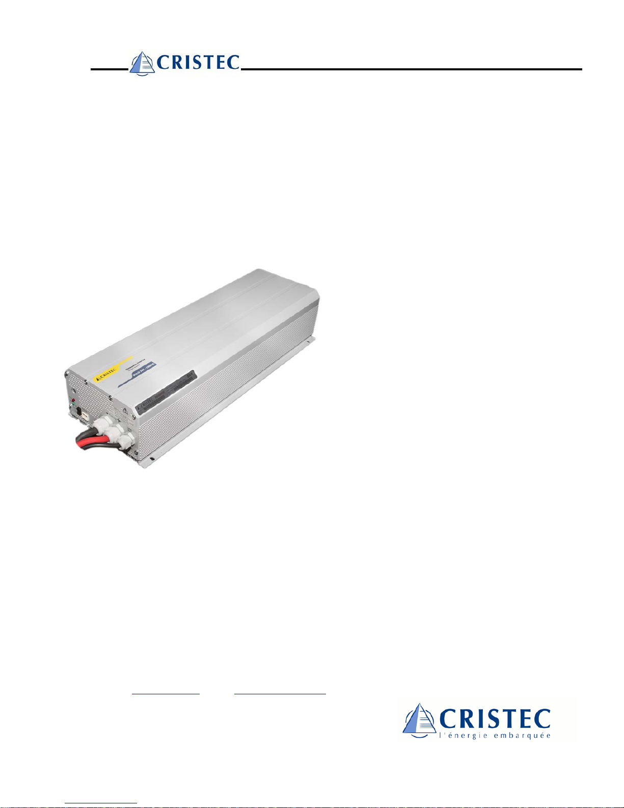
Onduleur sinusoïdal - Sinewave inverter
Gamme SOLO
SOLO range
Manuel d'utilisation et de montage
User's and Installer's Handbook
S.A.S. CRISTEC
31 rue Marcel Paul
Z.I. Kerdroniou est
29 000 QUIMPER - FRANCE
Tél. 33 (0)2 98 53 80 82 – Fax 33 (0)2 98 55 64 94
e-mail : info@cristec.fr - site : http://www.cristec.fr
SOLO 24V 2300W
SOLO 24V 3300W
SOLO 48V 1200W
SOLO 48V 2300W
SOLO 48V 3500W

SOLO3DEE 30015977
2
Table des matières
INTRODUCTION......................................................................................................................3
CONSIGNES IMPORTANTES.................................................................................................3
APPLICATIONS ET PERFORMANCES .................................................................................3
PRESENTATION ..................................................................................................................... 4
LIEU DU MONTAGE...................................................................................................................4
FIXATION................................................................................................................................4
RACCORDEMENT................................................................................................................... 4
UTILISATION...........................................................................................................................4
COMMANDE A DISTANCE..........................................................................................................5
RÉGLAGES .............................................................................................................................5
Standby Level (1) .............................................................................................................5
Procédure de réglage.......................................................................................................5
SURVEILLANCE......................................................................................................................5
INDICATEURS..........................................................................................................................5
Run - LED verte (3) ..........................................................................................................5
Fault - LED rouge (2)........................................................................................................5
SÉCURITÉ................................................................................................................................6
FUSIBLES INTERNES.............................................................................................................6
ENTRETIEN .............................................................................................................................6
PRESCRIPTIONS ....................................................................................................................6
EXCLUSION DE LA RESPONSABILITE................................................................................6
DECLARATION DE CONFORMITE CE.................................................................................. 6
DESCRIPTIF ET PLAN DE CABLAGE...................................................................................7
DONNEES TECHNIQUES.......................................................................................................8

SOLO3DEE 30015977
3
Introduction
Les onduleurs de la série SOLO ont été conçus
de manière à répondre aux besoins tant
industriels que domestiques. Ils répondent aux
plus hautes exigences de confort, de sécurité et
de fiabilité.
Chaque appareil conçu pour le réseau
électrique public 230V / 50 Hz peut s’y brancher
sans aucun problème.
La série "SOLO" est la solution idéale comme
source de tension partout où le réseau public
n’est pas présent.
Veuillez lire attentivement les instructions de
raccordement et les transmettre au monteur qui
câblera l'installation de manière à éviter tout
dysfonctionnement. Ainsi vous disposerez
d'une installation moderne, fiable et conforme
aux normes.
En cas de doute ou de question, n'hésitez pas
à contacter votre vendeur spécialisé qui saura
vous renseigner.
Consignes importantes
Un montage incorrect peut endommager
l'appareil, entraîner un mauvais fonctionnement
ou mettre en danger les utilisateurs.
L’appareil en fonction génère de hautes
tensions pouvant être fatales en cas de contact.
Le travail sur l'onduleur doit donc faire l'objet
d'une attention toute particulière. Les points
suivants doivent absolument être respectés :
•L'installation du "SOLO" ainsi que sa mise
en service doivent être réalisés
exclusivement par une personne
compétente.
•En cas de panne les réparations ne peuvent
être effectuées que par une personne
expressément désignée par la société
CRISTEC et spécialement formée à cet
effet.
Attention! L’ouverture de l’appareil ou
l'utilisation non conforme des onduleurs
SOLO entraîne la perte immédiate de la
garantie.
Aucun appareil générateur de courant ou de
tension ne doit être connecté à la sortie de
l'onduleur car il peut entraîner la destruction de
celui-ci (réseau public, génératrice ...).
Pour l'utilisation de batteries, veuillez vous
conformer aux directives d'utilisation du
fabricant.
IMPORTANT: Après déconnexion de la
batterie, la tension de sortie (230V) peut
subsister encore pendant 30 secondes.
L'aération de cet appareil ne doit en aucun cas
être bouchée. En cas de montage dans une
armoire, assurez-vous que l'évacuation de la
chaleur soit possible et suffisante.
L’installation et le montage de cet appareil doit
être conforme aux normes en vigueur dans le
pays.
Ce document fait partie intégrante de
l'onduleur, il doit être transmis à chaque
livraison et tenu à disposition de toute personne
travaillant sur l'installation.
Applications et Performances
De part sa conception moderne et ses
spécifications techniques, l'onduleur SOLO est
utilisable dans pratiquement toutes les
applications de manière simple et peu
coûteuse.
Tous les appareils fonctionnant sur le réseau
électrique public (230V - 50Hz) sont utilisables
avec l’onduleur (Jusqu'à la puissance nominale
de l'onduleur).
L'onduleur génère une tension de sortie
parfaitement sinusoïdale réglée avec une
excellente précision grâce à un système de
régulation de haute technologie.
Ainsi la tension de sortie est parfaitement
indépendante de la charge et de la fluctuation
de tension de la batterie.
Tous les onduleurs de la série SOLO sont
protégés contre les surcharges et les courts-
circuits.
Pour des raisons évidentes de sécurité,
l'onduleur ne se ré-enclenche pas
automatiquement après une erreur (surcharge,
court-circuit... )

SOLO3DEE 30015977
4
3500W
3300W
2300W
1200W
335mm
535mm
735mm
200mm
Présentation
Les onduleurs Serie SOLO sont livrés
complètement équipés, avec les câbles de
batterie, le câble 230V et le manuel d’utilisation.
Lieu du montage
Le choix du lieu de montage de l'onduleur doit
respecter les points suivants :
•A l'abri des personnes non autorisées.
•Dans une pièce sèche, sans condensation.
•Pas directement au-dessus des batteries.
•Aération libre.
•Rien ne doit être déposé sur l’appareil.
•Pour la ventilation une zone de 20 cm au
dessus de l’appareil et une zone de 20 cm
au dessous doivent être laissées libres.
Fixation
L'onduleur est prévu pour une utilisation
uniquement verticale et une pose murale. La
fixation doit être faite à l'aide des quatre trous
accessibles depuis l'extérieur de l'onduleur (∅
5,5 mm).
Les vis de fixation ne font pas partie du matériel
livré avec l'onduleur.
Attention :
Le boîtier de l’onduleur peut atteindre des
températures élevées (80 °C)
Raccordement
•Vérifier que l’interrupteur (4) est en position.
« OFF »
•Raccorder tout d’abord la sortie 230V (6) à
une prise, de manière à éviter tout contact
intempestif ultérieur.
Contrôler la tension et la polarité de la
batterie!
•La tension de la batterie doit correspondre à
celle prévue par la fiche technique de
l’onduleur.
•Raccordement de la batterie:
Cette connexion doit être faite avec le plus
grand soin en respectant impérativement la
polarité sous peine d'endommager
l'appareil.
•S’assurer que les connexions soient
correctement serrées.
Utilisation
Après le branchement de l'onduleur, vérifier
que les utilisateurs soient correctement
raccordés et qu’il n’y ait aucun contact
accidentel possible entre la sortie « Line OUT »
(6) et une personne.
L’appareil en fonction génère de hautes
tensions pouvant être fatales en cas de
contact!
L’onduleur peut être enclenché par le
basculement du commutateur de commande en
position « Auto ». L’indicateur de mise en
fonction -LED verte -(3) s’allume.
Si aucun consommateur n’est présent, après
quelques secondes la LED clignote indiquant le
passage en mode veille ou « standby ». En
présence d’un consommateur, la LED verte
reste allumée indiquant la présence
permanente du 230V à la sortie.
Si l’on souhaite désactiver le mode standby,
mettre alors le commutateur de commande en
position « Lock ». L’onduleur sera alors en
permanence en fonction.
Attention! Avec le mode « lock », la
consommation à vide de l’onduleur est 15 à
20 fois plus grande!

SOLO3DEE 30015977
5
Commande à distance
L’onduleur peut être commandé à distance à
l’aide d’un interrupteur (bi-stable) raccordé au
connecteur « Faston »(5) sur la face inférieure
de l’appareil. L’interrupteur principal (4) reste
prioritaire pour le mode de fonctionnement de
l’appareil. Lorsque l’interrupteur est ouvert
l’onduleur est en fonction.
Réglages
Standby Level (1)
La mise en marche de l'onduleur, lors du
fonctionnement en mode automatique, est
commandée par la détection d'une charge. Il
est possible de régler la charge minimale
détectée à l'aide de cette fonction entre 0,3 et
20 Watts. Le réglage d’usine est de 2 watts
et dispense généralement l’utilisateur de
tout réglage.
Procédure de réglage
•Assurez-vous qu’aucun appareil n’est
raccordé.
Attention à la présence de consommateurs
cachés tel que télévision, fax, vidéo, etc., qui
possèdent un mode veille et restent
consommateurs même après mise hors
fonction!
•Mettre l’onduleur en position « Autom. »
•Introduire délicatement un tournevis N°1
dans le trou (1) prévu à cet effet et tourner
doucement jusqu’à sentir l’insertion dans la
fente de la vis de réglage.
•Tourner sans appuyer dans le sens horaire
jusqu’à l’arrêt. (ne pas forcer!)
•Attendre que la LED verte clignote.
•Enclencher la charge minimale que vous
souhaitez détecter.
•Tourner sans appuyer dans le sens anti-
horaire jusqu’à ce que l’onduleur
s’enclenche. (LED verte allumée)
•Vérifier que l’onduleur retourne en mode
stand-by quelques secondes après
déclenchement de toutes les charges.
Attention: En position maximum anti-horaire,
l’onduleur reste en fonction même en l’absence
de toute charge.
Surveillance
La tension des batteries est surveillée. Durant
l'utilisation, la plage de tension doit être
comprise entre :
22.8 V et 32 V pour les modèles 24 Volts,
45.6 V et 61 V pour les modèles 48 Volts.
Hors de ces valeurs, l'onduleur est
automatiquement mis hors fonction.
Ces valeurs sont données pour un
fonctionnement à vide, elles sont
automatiquement corrigées en fonction de la
charge.
De même la température interne et la
puissance maximale sont surveillées.
En cas de surcharge prolongée ou d’aération
déficiente, Il n’est possible de redémarrer
l’onduleur qu’après refroidissement de celui-ci.
Indicateurs
Run - LED verte (3)
Allumée: L'onduleur est enclenché. La tension
230 V est présente à la sortie.
Clignotante: Indique que l’onduleur est en
mode « Autom. » et qu’aucune charge n’est
détectée par le système standby.
! La tension 230 V est présente par
intermittence!
Fault - LED rouge (2)
L'onduleur est arrêté:
•La tension de batterie est incorrecte
•Après une surcharge, une surchauffe ou un
court-circuit
Pour réinitialiser l’onduleur après une condition
de faute, mettre l’interrupteur (4) en position
« OFF » durant 15 secondes puis réenclencher.
SOLO3DEE 30015977
6
Sécurité
L'onduleur est protégé de manière interne
contre les surcharges et les courts-circuits. En
cas de défaut de cette protection, l'onduleur est
équipé d'un fusible (protection d'incendie). Si le
fusible est cassé, l’installation doit être
contrôlée et le fusible changé par du personnel
compétent.
Fusibles internes
Fusible
Onduleur SOLO (mod.)
50A
48V-1200W
80A
48V-2300W
100A
48V-3500W
2*100A
24V-2300W
2*125A
24V-3300W
L’installation d’un fusible de plus forte
intensité est dangereuse pour la sécurité de
l’installation et n’améliore pas les
caractéristiques de l’onduleur.
Entretien
Les onduleurs de la série "SOLO" ne
nécessitent aucun entretien particulier. Le
boîtier peut éventuellement être nettoyé avec
un chiffon humide (pas mouillé).
Si un dysfonctionnement devait apparaître,
l'onduleur doit être envoyé au fournisseur, dans
son emballage d’origine, pour contrôle.
Prescriptions
Dans tous les cas le montage et l’installation
doivent être réalisés par du personnel
compétent, en conformité avec les prescriptions
et règlements nationaux. Veuillez vous en
informer auprès des organismes compétents.
Exclusion de la responsabilité
La pose, la mise en fonction, l'utilisation, la
maintenance et le service ne peuvent pas faire
l'objet d'une surveillance par la société
CRISTEC. Pour cette raison, nous déclinons
toute responsabilité pour les dommages, les
coûts ou les pertes résultants d'une installation
non conforme aux prescriptions, d'un
fonctionnement défectueux, ou d'un entretien
déficient.
L’utilisation des onduleurs CRISTEC relève
dans tout les cas de la responsabilité du client.
Cet appareil n’est pas conçu ni garanti pour
l’alimentation d’installation destinée à supporter
la vie, ou toute autre installation critique
comportant des risques potentiels de dégât
important à l’homme ou à l’environnement.
Nous n'assumons aucune responsabilité pour
les violations de droits de brevets ou d'autres
droits de tiers résultant de l'utilisation de
l’onduleur.
CRISTEC se réserve le droit de toute
modification sur le produit sans communication
préalable.
Déclaration de conformité CE
La société CRISTEC déclare que les appareils
mentionné dans cette notice sont conformes
aux normes ou documents de
normalisation suivants :
EN 50081 I/II, EN 50014 -
50022, IEC 801 II / III / IV, CEI 555
Quimper, le 15 juin 1999

SOLO3DEE 30015978
7
Descriptif et plan de câblage
Commande à distance
(Remote control)
Faston 6x0,8mm
Entrée - de la batterie
Entrée + de la batterie
Sortie 230 Vac (Attention! Haute tension!)
Connecteur pour commande à distance
Commutateur de commande
Indicateur de mise en fonction (LED verte)
Indicateur de défaut (LED rouge)
Réglage du niveau de mise en veille (standby)
!!!! Vérifier la polarité des batteries !!!!
Longueur des câbles max. 2 m.! Utiliser des
batteries adaptées à la puissance de l’onduleur:
Cbatt [Ah] = 5 x Pnom / Unom
(Cette valeur peut être divisée par trois pour des
applications de courte durée).
Câblage de la batterie
Brun = L
Jaune-vert =
Bleu = N
Sortie 230 Vac (Line Out)
(Pas de réglage sur SITP)
Entrée - de la batterie
1
2
3
4
5
8
7
6
5
4321
87
6
SI 12XX - 3548 SI 4XX - 8XX
7
6
5
4
3
2
1
6
8
+Solar charger
910 11
12
9
10
11
12 Contact d'alarme 60V/0,5A (libre de potentiel)
Entrée module solaire (2,5mm#)
Indicateur "batterie en charge"(jaune)
indicateur "batterie chargée" (vert)
OPTIONS

SOLO3DEE 30015978
8
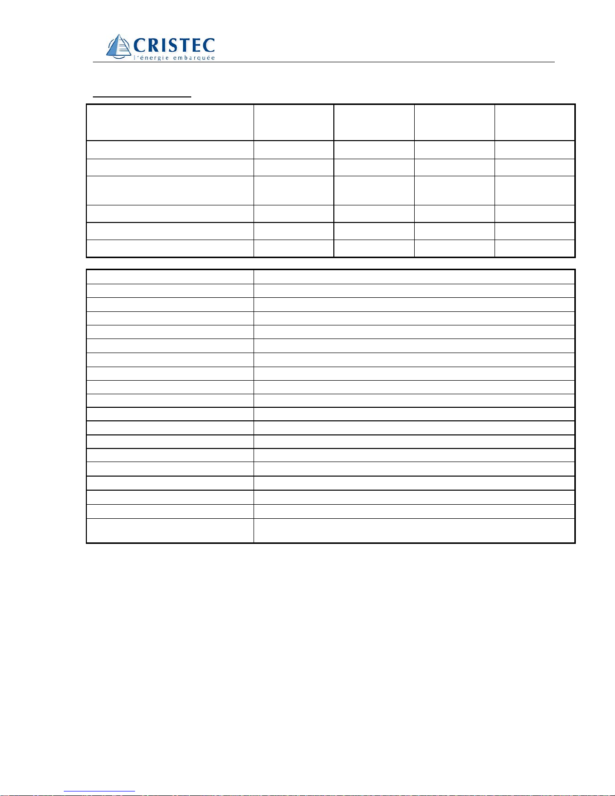
Données techniques
Modèle SOLO
48V 1200W 24V 2300W
48V 2300W 24V 3300W 48V 3500W
Tension d’entrée (Unom) [V] 48 24V/48 24 48
Puissance nominale [W] 1200 2300 3300 3500
Courant « Standby » [mA]
Consom. « ON » à vide [W] 12
4.8 25/17
9 25
13 30
17
Rendement maximum [%] 95 95 95 95
Longueur L x 124 (H) x 215 (l) [mm] 391 591 636 791
Poids [kg] 13.2 22.8 29 31
Tension d’entrée
Min. - Max.: < Unom x 0.95 à Unom x 1.33
Correction dynamique de Umin.
- 10% à Pnom
Tension de sortie
Sinus 230 Vac
±
3%
Distorsion harmonique
< 2% (à Pnom)
Comportement dynamique
De 0% à 100% sur saut de charge. Normalisation: 0.5 ms
Fréquence
50 Hz
±
0.01% (Crystal control)
Détection de la charge (standby)
Réglable: 0.3
→
20 W
Puissance maximale 15 min
1.3 – 1.6 x Pnom / 25°C
Puissance maximale 3 min
1.6 – 2 x Pnom / 25°C
Puissance crête 5s
3.5 x Pnom
Charge asymétrique
Jusqu’à 2 x Pnom
Cos
ϕ
0.1 – 1
Protections
Surcharge/Surchauffe/Court-circuit/Inversion polarité par fusible interne
Indice de protection IP
IP 20 selon DIN 40050/ IP 23 avec capot
Ventilation forcée
Dès 45°C
±
3°C
Protection de surchauffe
75°C
±
3°C
Capacité batterie requise >
5x Pnom/Unom (valeur recommandée)
Seuil acoustique
Sans ventilation:
<
10 dB Avec ventilation:
<
35 dB
Conformité CE
EN50081 I/II, EN 55014 - EN 55022, EN 61000-3-2
IEC 801 I/II/III/IV, CEI 555, IEC 1000-3-2, LVD 73/23/EEC
Autres spécifications sur demande (Ex: 115V/60Hz)
Ces données sont indicatives et susceptibles d’être modifiées sans préavis.

SOLO3DEE 30015978
9
Contents
INTRODUCTION....................................................................................................................10
IMPORTANT NOTES.............................................................................................................10
APPLICATIONS AND PERFORMANCES............................................................................10
PRODUCT PRESENTATION.................................................................................................11
LOCATION.............................................................................................................................11
FITTING................................................................................................................................11
CONNECTION .......................................................................................................................11
USE ........................................................................................................................................11
REMOTE CONTROL................................................................................................................12
ADJUSTMENTS......................................................................................................................12
Standby Level (1) ...........................................................................................................12
Adjustment procedure ....................................................................................................12
CONTROL..............................................................................................................................12
INDICATORS..........................................................................................................................12
Green Run - LED (3) ......................................................................................................12
Red Fault - LED (2) ........................................................................................................12
SAFETY..................................................................................................................................13
INTERNAL FUSES ................................................................................................................13
MAINTENANCE.....................................................................................................................13
LEGISLATION .......................................................................................................................13
LIMITATION OF LIABILITY...................................................................................................13
CE - DECLARATION OF CONFORMITY..............................................................................13
DESCRIPTION AND WIRING DIAGRAM .............................................................................14
TECHNICAL DATA................................................................................................................15

SOLO3DEE 30015978
10
Introduction
The SOLO sinewave inverters have been
designed to meet industrial and domestic needs.
They satisfy the highest demands of comfort,
safety and reliability.
Any device designed for the public electrical
network of 230V / 50 Hz can be connected to
them.
The SOLO inverters are the perfect solution as
sources of tension in any place where the public
network is not available.
Read the connection instructions thoroughly and
give them to the technician who is to install the
inverter so as to prevent any malfunction. Thus
you will have a modern and reliable installation
which meets requirements.
Should you have any doubt or question, do not
hesitate to contact your specialist salesperson
who will give you the best advice.
Important notes
A deficient assembly could damage the device,
cause function failures or potential damage to the
users.
The working device generates a high tension
which might be fatal in case of contact. So, any
manipulation of the inverter must be carried out
with utmost care. The following points must be
strictly observed :
The installation of the "SOLO" can only be
performed by a qualified technician.
In case of malfunction, only a technician specially
designated and trained by CRISTEC is allowed to
repair the device.
Warning :
Opening the inverters or using them
incorrectly will result in the immediate
loss of the warranty.
No current or tension generating devices (public
network, generator, ...) may be connected to the
output of the inverter because this could result in
its destruction.
As for the usage of batteries, follow the
manufacturer’s instructions.
Important :
After disconnecting the battery, the output
tension (230V) may still remain for 30
seconds.
The ventilation of the device should never be
obstructed. Should the device be installed in an
enclosed structure, make sure that ventilation is
possible and adequate.
The installation and assembly of the device must
follow the rules stipulated.
This document is an essential part of the inverter
and must always be carried with it and be at the
disposition of anyone working on the installation.
Applications and Performances
As well as its modern design and its technical
characteristics, the SOLO inverter is also easy
and economical to use in almost all applications.
All devices working within the public electrical
network (230V - 50Hz) may be used with the
inverter (up to its nominal power).
The inverter generates a perfectly sinusoid output
tension, precisely adjusted by a high technology
regulation system.
Thus, the output tension is totally independent of
the charge and the fluctuation of tension in the
battery.
All inverters in the SOLO series are protected
against overloading and short circuits.
Due to obvious safety reasons, the inverter is not
automatically reactivated after a failure (overload,
short circuit,…).

SOLO3DEE 30015978
11
Product presentation
The inverters of the SOLO series are presented
fully equipped, with battery cables, 230V cable
and the user's handbook.
Location
The place where the inverter is to be mounted
should meet the following requirements :
•Out of reach of non-authorised persons.
•In a dry place with no condensation.
•Not directly on top of the batteries.
•Adequate ventilation. No inflammable material
in the same room.
•Do not lay anything on the device.
•An area of 20 cm from the top and the bottom
of the device should be kept clear for the
ventilation.
Fitting
The inverter has been designed to be used only in
a vertical position and against the wall. The
inverter is fitted using the four external holes (∅
5,5 mm).
The fitting screws are not supplied with the
inverter.
Beware :
The casing of the inverter can reach high
temperature ( 80 °C )
Connection
•Check the switch (4) is in “ OFF ” position.
•First connect the 230V outlet (6) to the user
device, so as to prevent any possible
accidental contact.
Check the tension and polarity of the battery !
•The tension of the battery should coincide with
that mentioned in the technical characteristics
of the inverter.
•Battery connection :
This connection should be done very carefully
observing the polarity in order not to damage
the device.
•Check that the connections are fixed correctly.
Use
After connecting the inverter, make sure the user
devices are correctly plugged in and that there is
no possible contact between the “ Line OUT ” (6)
and a person.
The working device generates high tensions
which could be fatal!
The inverter can be activated by moving the
switch to the ‘Auto” position. The ‘on’ indicator -
green LED -(3) is illuminated.
If no user device is connected, the LED blinks
after some seconds, which indicates that the
“standby” mode has started. If a user device is
plugged in, the green LED remains illuminated,
indicating the uninterrupted presence of 230V in
the outlet. If you wish to deactivate the standby
mode, put the switch in “Lock” position. The
inverter will be then working continuously.
Warning :
With the “lock” mode, the no load
consumption of the inverter is 15 to 20 times
greater !
3500W
2300W
1200W
335mm
535mm
735mm
200mm
3300W
580mm
SOLO3DEE 30015978
12
Remote control
The inverter can be controlled remotely with a
switch (bi-stable) connected to the “Faston ” (5)
connector on the underside of the device. The
main switch (4) has priority over the working mode
of the device. If the remote switch is close, the
inverter is out of use.
Adjustments
Standby Level (1)
The activation of the inverter, when working in
automatic mode, is dictated by the detection of a
load. With this function, it is possible to adjust the
minimum load detected between 0,3 and 20
Watts. This level is factory adjusted to 2 watts
and so no further adjustment will probably be
needed.
Adjustment procedure
•Make sure that no device is connected.
Check for the presence of hidden users such
as television, fax, video, … which often have a
standby mode and remain working even after
being turned off !
•Put the switch in “’Autom.” position.
•Introduce a screw driver N°1 delicately in the
hole (1) provided and turn gently until you feel
the screw driver insert in the groove of the
screw.
•Turn clockwise until tight without pressing
(do not force!).
•Wait until the green LED blinks.
•Activate the minimum charge you wish to
detect.
•Turn the screw slowly anti-clockwise
without pressing until the inverter activates.
(green LED illuminated).
•Check that the inverter goes back to standby
mode a couple of seconds after deactivation of
all charges.
Warning: In maximum anti-clockwise position the
inverter continues to work even if there is no load.
Control
The tension of the batteries is submitted to
control. During their use, the tension must be
between the following ranges:
22.8 V and 32 V in the 24 Volt models,
45.6 V and 61 V in the 48 Volt models.
Outside these ranges the inverter is automatically
disconnected.
These values correspond to a no load situation
and they are automatically adjusted according to
the current of the battery.
The internal temperature and the maximum power
are also submitted to control.
In the case of prolonged overload or deficient
ventilation it is not possible to restart the inverter
until it has cooled down.
Indicators
Green Run - LED (3)
Illuminated: the inverter is connected. A 230 V
tension is present in the outlet.
Blinking: The inverter is in “’Autom.” mode and no
voltage is detected by the standby system.
A 230V tension is intermittently present!
Red Fault - LED (2)
The inverter is stopped:
•The tension of the battery is not correct
•After an overload, overheating or short circuit
To restart the inverter after a failure, put the
switch (4) in “’OFF” position for 15 seconds, then
connect again.

SOLO3DEE 30015978
13
Safety
The inverter is internally protected against
overloads and short circuits. Should this
protection fail, the inverter is equipped with a fuse
(fire protection). If the fuse is broken, qualified
technicians should control the installation and
change the fuse.
Internal fuses
Fuse
Inverter SOLO (mod.)
50A
48V-1200W
80A
48V-2300W
100A
48V-3500W
2*100A
24V-2300W
2*125A
24V-3300W
The use of higher fuse value will not improve
the performance of the inverter and will
degrade safety protection!
Maintenance
The SOLO inverters do not need any special
maintenance. The casing may be cleaned with a
damp cloth (not wet).
In the case of malfunction, the inverter should be
sent to the salesperson for control.
Legislation
In all cases the assembly and installation must be
done by qualified technicians, observing the
national requirements and rules stipulated. You
will find complete information about this in the
relevant institutions.
Limitation of liability
CRISTEC cannot control the installation, use and
maintenance of the inverter. Thus, we are not
responsible for damages, costs or losses resulting
from an installation which is not in accordance
with the regulations or inappropriate use or
maintenance.
The customer is always responsible for the use of
the inverters CRISTEC.
This device has not been designed and is not
warranted for use in life support apparatus or any
other critical apparatus with potential risks of
serious harm to people or to the environment.
We do not accept any responsibility for any
violation of patent rights or other third person
rights resulting from the use of the inverter.
CRISTEC reserves the right to modify their
products without previous notice
CE - declaration of conformity
CRISTEC declares under that products
mentioned on this manual are in conformity with
the following standards or standardisation
documents:
EN 50081 I/II, EN 50014 - 50022, IEC 801 II / III /
IV, CEI 555
Quimper : June 19th , 1999

SOLO3DEE 30015978
14
Description and wiring diagram
1
2
3
4
5
8
7
6
5
4 3 21
87
6
SI 12XX - 3548 SI 4XX - 8XX
7
6
5
4
3
2
1
6
8
+
Solar charger
910 11
12
9
10
11
12
Remote control
Faston 6x0,8mm
Plus battery
Output 230 Vac (Caution! High voltage!)
Remote control connector
Main switch
Run indicator (Green LED)
Fault indicator (red LED)
Standby level adjustment
(Not avalable with Twinpower option)
!!!! Check battery polarity !!!!
Max. cables lenth 2 m.! Battery size sould be
ajusted to the inverter’s power:
Cbatt [Ah] = 5 x Pnom / Unom
(This value could be divided by tree for short time
applications).
Battery connection:
Braun = L
Yellow-green
Blue = N
Line out 230 Vac
Minus battery
Alarm contact 60V/0,5A (potential free)
Solar panel connector (2,5mm#)
Indicator "Battery charging" (Yellow)
Indicator "battery full charged" (Green)
OPTIONS
SOLO3DEE 30015978
15
Technical data
Model SOLO
48V 1200W 24V 2300W
48V 2300W 24V 3300W 48V 3500W
Input voltage (Unom) [V]
48 24V/48 24 48
Nominal power [W]
1200 2300 3300 3500
« Standby » current [mA]
Power « ON » no load [W] 12
4.8 25/17
9 25
13 30
17
Maximum efficiency [%]
95 95 95 95
Length L x 124 (H) x 215 (W) [mm]
391 591 636 791
Weight [kg] Weight [kg]
13.2 26 30 31
Input voltage
Min. - Max.:
<
Unom x 0.95 to Unom x 1.33
Dynamic correction of Umin.
- 10% at Pnom
Output voltage
True sine 230 Vac
±
3%
Distortion
< 2% (at Pnom)
Dynamic behaviour
From 0% to 100% load change. Normalisation: 0.5 ms
Frequency
50 Hz
±
0.01% (Crystal control)
Charge detection (standby)
Adjustable: 0.3
→
20 W
Maximum power 15 min
1.3 – 1.6 x Pnom / 25°C
Maximum power 3 min
1.6 – 2 x Pnom / 25°C
Peak power 5s
3.5 x Pnom
Asymmetric load
Up to 2 x Pnom
Cos
ϕ
0.1 – 1
Protections
Overload/Overheat/Short-circuit/Reverse polarity by internal fuse
IP protection index
IP 20 complies with DIN 40050/IP 23 with top cover
Forced ventilation
From 45°C
±
3°C
Overheating protection
75°C
±
3°C
Required battery capacity
>
5x Pnom/Unom (recommended value)
Acoustic level
Without ventilation:
<
10 dB With ventilation:
<
35 dB
EEC conformity
EN50081 I/II, EN 55014 - EN 55022, EN 61000-3-2
IEC 801 I/II/III/IV, CEI 555, IEC 1000-3-2, LVD 73/23/EEC
Other specifications on request (Ex: 115V/60Hz).
These data are for information only and may change without notice.

SOLO3DEE 30015978
16
This manual suits for next models
4
Table of contents
Languages:
Other Cristec Inverter manuals


