Cross Technologies 2001-21 User manual

INSTRUCTION MANUAL
MODEL 2001-21 Chassis
CROSS TECHNOLOGIES, INC.
6170 SHILOH ROAD
ALPHARETTA, GEORGIA 30005
(770) 886-8005
FAX (770) 886-7964
WEB www.crosstechnologies.com
E-MAIL [email protected]
Data, drawings, and other material contained herein are
proprietary to Cross Technologies, Inc., and may not be
reproduced or duplicated in any form without the prior
permission of Cross Technologies, Inc.
When ordering parts from Cross Technologies, Inc., be sure to
include the equipment model number, equipment serial
number, and a description of the part.
First Edition, February 2000 Rev 0

INSTRUCTION MANUAL
MODEL 2001-21 Chassis
TABLE OF CONTENTS PAGE
Warranty ..............................................2
1.0 General.................................................3
1.1 Equipment Description..........................3
1.2 Technical Characteristics........................3
2.0 Installation ............................................3
2.1 Mechanical .......................................3
2.2 Indicators..........................................4
2.3 Input / Output Signals ..........................4
2.4 Installing and Removing Series 1600 PCB’s. 4
2.5 Installation ........................................5
CROSS TECHNOLOGIES, INC.
6170 SHILOH ROAD
ALPHARETTA, GEORGIA 30005
(770) 886-8005
FAX (770) 886-7964
Toll Free 888-900-5588
WEB www.crosstechnologies.com
E-MAIL [email protected]
2001-21 Manual Page 2 2/17/00
WARRANTY - The following warranty applies to all Cross Technologies, Inc. products.
All Cross Technologies, Inc. products are warranted against defective materials and
workmanship for a period of one year after shipment to customer. Cross Technologies,
Inc.’s obligation under this warranty is limited to repairing or, at Cross Technologies, Inc.’s
option, replacing parts, subassemblies, or entire assemblies. Cross Technologies, Inc. shall
not be liable for any special, indirect, or consequential damages. This warranty does not
cover parts or equipment which have been subject to misuse, negligence, or accident by the
customer during use. All shipping costs for warranty repairs will be prepaid by the
customer. There are not other warranties, express or implied, except as stated herein.

MODEL 2001-21 Chassis
SECTION 1 GENERAL
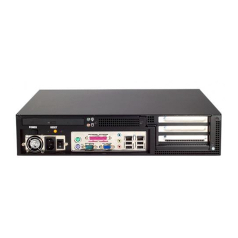
1.1 Equipment Description- The 2001-21 Chassis holds two Wegener 1600 cards and can hold two
cards which have connectors through the rear panel cutout. Plus and minus 15 VDC is provided by the 2000-
01 power supply and a harness connects power to each card via a three pin mini-DIN connector. The DB9
connector provides connections to pins 4,5, and 15 of the edge card connector (pins 2, 3, and 9 of the DB9)
and ground (pins 1 and 5 of the DB9). The extrusion length is 12.17” which holds each card securely in the
extrusion. No front panels allow easy access to card controls.
2000 POWER SUPPLY
CROSS TECHNOLOGIES, INC.
POWER
FRONT PANEL
CAUTION - RISK OF ELECTRICAL
SHOCK - DO NOT OPEN!!!
-15 GND +15
CROSS TECHNOLOGIES, INC.
90-260 VAC
47 - 63 HZ
FUSE 2 A
J2
J3
1
5
6
9
J2 J3
1
5
6
9
REAR PANEL
Figure 1.1 Model 2001-21 Front and Rear Panels
1.2 Technical Characteristics
TABLE 1.0 2001-21 Chassis SPECIFICATIONS
Characteristics Specifications*
Number of Card Positions 2
Indicators
Power Green LED indicate 2000-01 Power supply on
Other
AC Power, Input. 90- 260 VAC, 47 - 63 Hz, via 2000-01 power supply
DC Power, max. +15VDC, 1200ma; -15VDC, 500ma; via 2000-01 power supply
Size 19” W X 1 3/4” H X 12.5” D
*Specifications subject to change without notice
2.0 Installation
2.1 Mechanical - The 2001-21 has two aluminum extrusions which house 1600 PC cards. The 2001-21
has a 1 3/4” X 19” panel that can be mounted to a rack using the 4 holes at the ends. Both PC Card housings
derive ± 15V from the 2000-01 regulated power supply. Figure 2.1.Shows how a module housing and card
is assembled.
2001-21 Manual Page 3 2/17/00

EXTRUSION
BACKPLANE
REAR SCREWS
(4EA)
FRONT SCREWS (4EA)
FRONT PANEL PCB
ASSEMBLY
R3 Rack Panel
Figure 2.1 2001-21 Module housing assembly Drawing
2.2 Indicators - Green LED on 2000-01 Power Supply indicates power is applied..
2.3 Input / Output Signals - Figure 2.2 shows each position’s connectors.
2.4 Installing and Removing Series 1600 PCBs -
INSTALLING PC CARD
1) Remove card extractor from the 1600 card by pushing out the pin that holds it in.
2.) Remove four (4) rear panel screws of the extrusion (see Figure 2.1).
3.) Always remove power when installing the PCB in to the extrusion. Make sure the shield (if the
PC Card has a shield) goes in the lower channel and the PCB in the next channel above that in the extrusion.
4.) Gently push the backplane and PCB assembly completely in to the extrusion so PCB front edge
goes to the rack front panel. Make sure the PC card edge connector is securely mated with the backplane
connector.
5.) Install four (4) rear panel screws of the extrusion (see Figure 2.1).
6.) Connect DC power harness 3-pin mini-DIN connector.
REMOVING PC CARD
1.) Remove DC power harness 3-pin mini-DIN connector.
2.) Remove four (4) rear panel screws of the extrusion (see Figure 2.1).
3.) Gently pull the backplane and PCB assembly completely out of the extrusion.
2001-21 Manual Page 4 2/17/00

2.5 Operation -
1.) Install PC Cards as in section 2.4
2.) Connect the ± 15 VDC harness between the 2000-01 and the extrusion backplanes
3.) Connect signals to the PC cards as needed
4.) Connect the 2000-01 power supply to 115 VAC, 60 Hz. See the Green LED on the 2000-01 is on.
J2 J3
1
5
6
9
-15 +15
GND
Card Inputs
Outputs - The signals
on 1600 PC cards that
go through the
opening in the
backplane
J2 - DC IN - The +15
VDC AND -15 VDC
regulated DC voltage
from the wall power
supply
J3 - Card I/O - DB9 female connector
PIN - FUNCTION
1,5 - Ground
2- Connects to Pin 4 of the 1600 edge connector
3- Connects to Pin 5 of the 1600 edge connector
4,6,7,8 - No Connection
9- Connects to Pin 15 of the 1600 edge connector
TABLE 2.0 2001-21 DB9 to Card Edge Connector Pins
TABLE 2.0 2001-21 DB9 to Card Edge Connector Pins
DB 9 PIN 1600 CARD EDGE CONNECTOR PIN
1 GND (1,18)
2 4
3 5
4NO CONNECTION
5GND (1,18)
6NO CONNECTION
7 NO CONNECTION
8 NO CONNECTION
915
Figure 2.2 2001-21 Connectors and DB9 Pin outs
CAUTION - RISK OF ELECTRICAL
SHOCK - DO NOT OPEN!!!
-15 GND +15
CROSS TECHNOLOGIES, INC.
90-260 VAC
7 - 63 HZ
FUSE 2 A
J2
J3
1
5
6
9
J2
J3
1
5
6
9
Figure 2.3 2001-21 DC Power Harness
2001-21 Manual Page 5 2/17/00
Table of contents
