Cross Technologies 1599-10 User manual

Instruction Manual
Model 1599-10
Noise Source
March 2010 Rev. A
Data, drawings, and other material contained herein are proprietary to Cross Technologies, Inc.,
but may be reproduced or duplicated without the prior permission of Cross Technologies, Inc.
for purposes of operating the equipment. Printed in USA.
When ordering parts from Cross Technologies, Inc., be sure to include the equipment
model number, equipment serial number, and a description of the part.
CROSS TECHNOLOGIES, INC.
6170 Shiloh Road
Alpharetta, Georgia 30005
(770) 886-8005
FAX (770) 886-7964
Toll Free 888-900-5588
WEB: www.crosstechnologies.com
E-MAIL: [email protected]
1599-10 Manual, Rev. A Page 1 01/07/10

INSTRUCTION MANUAL
MODEL 1599-10 NOISE SOURCE
TABLE OF CONTENTS PAGE
Warranty 2
1.0 General 3
1.1 Equipment Description 3
1.2 Technical Characteristics 4
2.0 Installation 5
2.1 Mechanical 5
2.2 Controls and Indicators 5
2.3 Input/Output Signals 5
2.4 Jumper Settings 5
2.5 Installation/Operation 6
2.5.1 Local Operation 6
2.5.2 Noise Level Settings, Continuous Mode 6
2.5.3 Noise Level Settings, Preset Level Mode 8
2.5.4 Selecting Fileter Bandwidths 9
2.5.5 Remote Operation 10
2.5.6 Remote Control DOS Program 10
3.0 Circuit Description 13
3.1 Block Diagram Description 13
3.2 Control Operation for 1599-10 13
3.2.1 General 13
3.2.2 Noise Level Settings, Continuous Mode 14
3.2.3 Noise Level Settings, Preset Level Mode 14
3.2.4 Selecting Filter Bandwidths 14
4.0 Environmental Use Information 16
WARRANTY - The following warranty applies to all Cross Technologies, Inc. products.
All Cross Technologies, Inc. products are warranted against defective materials and
workmanship for a period of one year after shipment to customer. Cross Technologies, Inc.’s
obligation under this warranty is limited to repairing or, at Cross Technologies, Inc.’s option,
replacing parts, subassemblies, or entire assemblies. Cross Technologies, Inc. shall not be
liable for any special, indirect, or consequential damages. This warranty does not cover parts
or equipment which have been subject to misuse, negligence, or accident by the customer
during use. All shipping costs for warranty repairs will be prepaid by the customer. There
are not other warranties, express or implied, except as stated herein.
1599-10 Manual, Rev. A Page 2 01/07/10
1599-10 NOISE SOURCE
SECTION 1 GENERAL
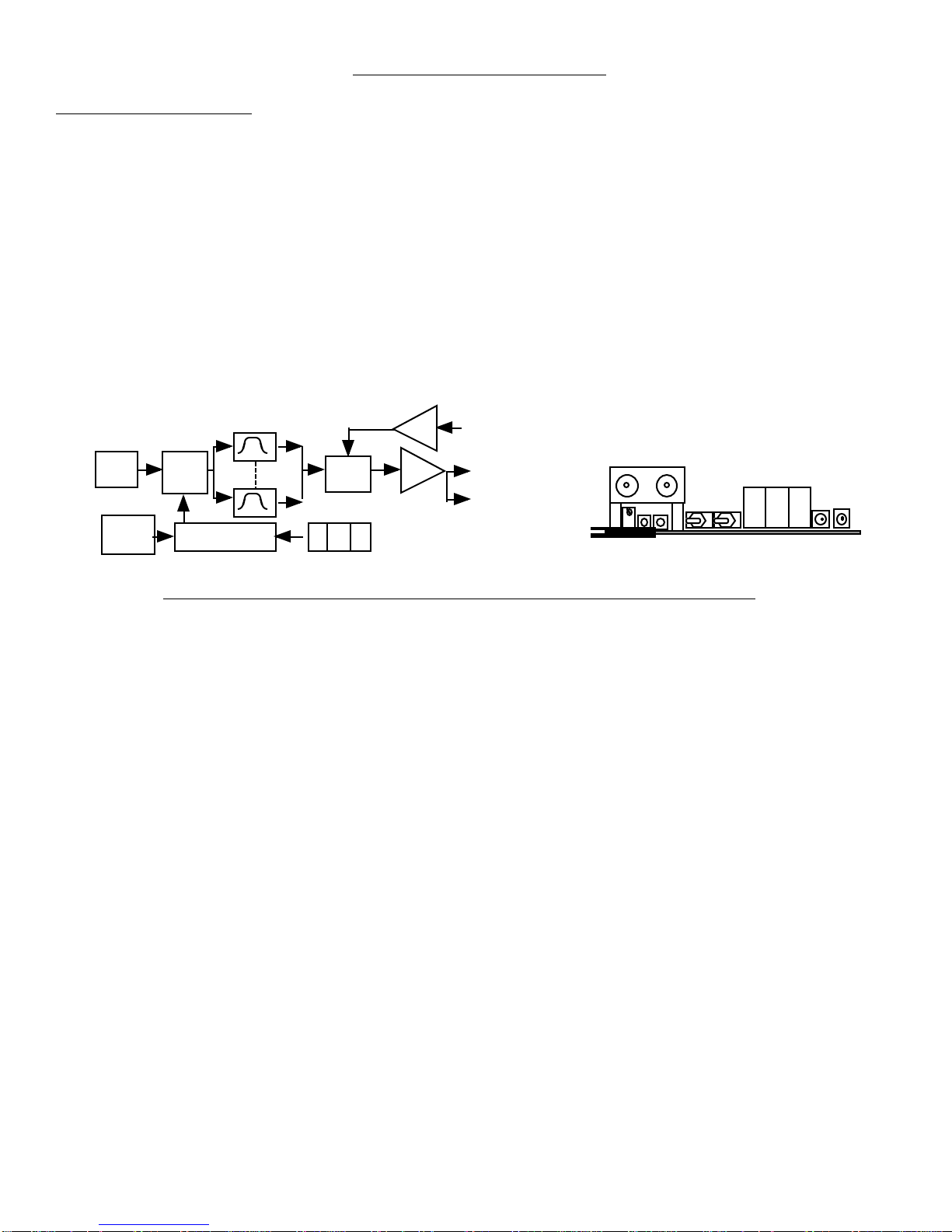
1.1 Equipment Description- The Model 1599-10 Noise Source provides 70 MHz band limited noise in 0.1dB
increments and summing of an external signal. Broad band noise goes to precision attenuators controlled by front
panel “up” and “down” pushbutton switches via the microprocessor controller. The front panel display shows
C/No or attenuation of the noise from a 50 dB- Hz C/No level calibrated for a -20 dBm carrier level. Bandpass
filters are selected with on board jumpers to band limit the noise at 70 MHz. The 1599-10 has a front panel red
LED that lights if the ambient temperature is outside the +20 to +40 C calibrated temperature range. A yellow LED
on the front panel indicates if in remote operation.
FIGURE 1.1 1599-10 Noise Source Block Diagram and Front Panel
NOISE
GEN
Atten. or
C/No
CONTROLLER
Noise Filters
1 3. 8
Voltage
variable
Atten Power
Comb.
Temp.
Detect.
Ext. IF
In
Output
-10 DB
Output
Monitor
13. 8
1599-10 Manual, Rev. A Page 3 01/07/10

1.2 Technical Characteristics
TABLE 1.0 1599-10 NOISE SOURCE SPECIFICATIONS
Characteristics Specifications*
Input Characteristics- carrier input
Input Impedance/RL 75 unbalanced/15 db
Frequency 70 MHz center
Input Level -20 dBm
Gain 0 dB ± 0.1 dB
Output Characteristics
Impedance/RL 75 unbalanced/15 db
Frequency Band 50 - 90 MHz
Level Noise power range allows C/No range of 50 to 90 dB-Hz with a -20 dBm
carrier for 10 MHz BW and 60 to 90 dB-Hz for 40 MHz bandwidth.
Monitor level -10 dB down from main output
Channel Characteristics - Noise Source
BW(MHz) 10 MHz or 40 MHz, Selectable @ 70 MHz IF
Frequency Response -3.0±1 dB, at stated bandwidths
±0.5 dB @ 0.7 X BW
Noise Power Accuracy ±0.25 dB, 60 - 80 dB-Hz C/No, 20 to 40 deg C
±0.5 dB, 50 - 60 and 80 - 90 dB-Hz C/No, 20 to 40 deg C
±0.5 dB, 60 - 80 dB-Hz C/No, 10 to 20, 40 to 50 deg C
Noise Power stability ±0.5 dB, 60 - 80 dB-Hz C/No, 20 to 40 deg C, 30 days
Controls
Test Carrier Toggle switch turns reference 70.0 MHz, -20.0 dBm carrier on and off.
Term Noise or Carrier Toggle switch terminates noise or external signal.
Output Level Potentiometer for Noise calibration.
Attenuation Push button switches with readout of attenuator or C/No setting.
Indicators
Alarm Red LED for temperature range (with FET open drain).
Remote Yellow LED lights when remote control is selected.
Level Three digit displays show C/No for a -20.0 dBm carrier or attenuation
from max noise level.
Other
DC Power, max. +15 VDC, 250 ma; -15 VDC, 120 ma
RF, IF Connectors BNC, female
*Specifications subject to change without notice
2.0 Intallation
1599-10 Manual, Rev. A Page 4 01/07/10

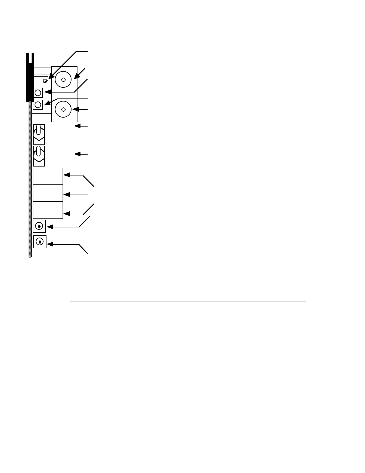
2.1 Mechanical - The 1599-10 goes in any slot of a 1601, 1651 or 1602 mainframe. It derives ±15 V from the
mainframe. Figure 2.1 shows the 1599-10 in slot 1.
1599-10 Noise Source ( fits in any slot in a 1601 or 1651 mainframe; slot 1 shown.
1599-10 Noise Source ( fits in any slot of a 1602 mainframe; slot 1 shown)
FIGURE 2.1 1599-10 MAINFRAME INTERFACE
POWER SUPPLY
1 2 P. S. J10 J9 J7 J6 J4 J5 J1J3
POWER SUPPLY
1 2 3 4 5 6 7 8 9 P. S.
70 MHz SIGNAL IN
1602 FRONT
1601 REAR
1601 FRONT
J10
2
J30
J40
J45
J42 J41
J43 12
24 13
12 1
SIGNAL + NOISE OUT
J20
-10dB MONITOR
SIGNAL + NOISE OUT
1602 REAR
70 MHz SIGNAL IN
-10dB MONITOR
2.2 Controls and Indicators - Figure 2.2 shows front panel controls and indicators.
2.3 Input / Output Signals - Figure 2.3 shows the input and output signals to the 1599-10.
Figure 2.5 is a sketch of the 1601 position 1 and 2 interconnections for reference.
2.4 Jumper Settings - Figure 2.4 shows jumpers and other on-card controls.
1599-10 Manual, Rev. A Page 5 01/07/10

2.5 Installation / Operation -
2.5.1 Local Operation -
1.) Check that on-card jumpers are set to the desired positions (Figure 2.4)
2.) Install the 1599-10 in any slot of a 1602 or 1601 mainframe (Figure 2.1 shows installation in slot 1)
3.) Connect a -20.0 dBm 70 MHz signal to 70 MHz SIGNAL IN (Figure 2.1, Figure 2.3)
4.) Set the desired noise level by pushing SW2 or SW3. If numbers 0 to 9 appear when pushing SW2 or
SW3,
the 1599-10 is set for the preset level mode (with on-card jumper JP7, Figure 2.4).
See section 2.5.2 for noise level setting information.
5.) Be sure DS1 and DS5 are off (Figure 2.2).
8.) If needed, R48 can be adjusted (Figure 2.2) to SLIGHTLY adjust the noise level.
Note that this uncalibrates the 1599-10 from its factory calibration.
2.5.2 Noise Level Setting, Continuous Level Mode - In this mode, the noise level is selected by pushing the
up and down switches (SW2, SW3) on the front panel until the desired noise level is indicated on the front on the
display. The noise level displayed is either C/No based on a -20.0 dBm carrier input or attenuation from the
maximum 50 dB-Hz C/No noise level Note that in the 40 MHz filter setting, the maximum allowable noise level
corresponds to a 60 dB-Hz C/No and setting the the noise level higher causes the display to blink indicating an
abnormal condition. EEROM U20 stores the last noise level set so in the event of power failure the 1599-10 will
go to the noise level it was set to prior to the power outage. The front panel noise level setting switches increment
or decrement the noise level in 0.1 dB steps at approximately a 0.5 second rate. If the switch remains depressed
for approximately ten steps, the rate increases by a factor of ten.
1599-10 Manual, Rev. A Page 6 01/07/10
DS1 - Remote LED - Lights yellow when jumper JP9 is set to REMOTE. When this LED is on,
SW1, SW3, and SW4 on the front panel are disabled and these functions are controlled remotely
J4 - 70 MHz IF Input - 75, BNC 70 MHz input . Input must be at -20.0 dBm for a calibrated
C/No reading.
J4 - -10dB Monitor - 75, BNC -10dB monitor of the 70 MHz output .
SW1 - Terminate Noise or Carrier - Terminates noise or carrier for calibration purposes.
This switch is disabled when in the REMOTE control mode.
FIGURE 2.2 1599-10 Front Panel Controls and Indicators
R48 - Noise Level Adjustment - 10 turn potentiometer that adjusts the noise level by ± 1.0 dB
for very small noise level adjustments to calibrate the 1599-10 to a specific level
DS5 - Alarm LED - Lights red when ambient temperature exceeds approximately 45 degrees C
SW4 - Test Carrier On/Off - Turns -20.0 dBm, 70.0 MHz Test carrier on and off. This carrier is
used as a reference to calibrate the desired carrier on a spectrum analyzer This switch is disabled
when in the REMOTE control mode.
-ON TEST
-OFF CARRIER
13. 8
-TERM NOISE
-OPERATE
-TERM CARRIER
DS2 - 10 dB
DS3 -
1 dB DS2, DS3, DS4 - Noise Level Displays - Display the desired output noise level in
C/No or dB below the maximum -50 dB-Hz level.
SW2 - UP Noise Level Control Pushbutton Switch - When in Continuous Noise Level mode
(as set by jumper JP7), when pushed will increment noise level in 0.1 dB steps at about a 0.5 second rate.
If held in for about 10 steps, will increment noise level in 0.1 dB steps at about a 0.05 second rate.
When in Preset Noise Level mode (as set by jumper JP7), when pushed momentarily will display the
preset level number its on. If held in will increment preset level number and when released will display
the noise level of the selected preset level.
SW3 - DOWN Noise Level Control Pushbutton Switch - Same as SW2 except decreases
noise level or preset level. PUSHING SW2 and SW3 simultaneously displays the on-card temperature in
degrees C (typically 5-7 degrees above ambient room temperature. An alarm condition occurs
about 50 degrees)
DS4 -
0.1 dB
1599-10 Manual, Rev. A Page 7 01/07/10

1599-10 Rear
FIGURE 2.3 1599-10 Inputs and Outputs
Pin 15 (J10P11) - Alarm FET open drain output -
Provides a short to ground (100 ma max) if alarm occurs.
Pin 1 (J10P12) - Ground
Pin 18 (J10P12) - Ground
Pin 9 (J10P5 - +15 VDC - 250 ma max, 220 typical
Pin 11(J10P7) - -15 VDC - 120 ma max, 100 typical
Pin 4 (J6P1) - Remote Control Data Out -RS232C,
2400 B/s ASYNC (8N1) data to external computer. Used for
handshaking during remote operation and auto-calibration.
Pin 5 (J6P3) - Remote Control Data In - RS232C,
2400 B/s ASYNC (8N1) data from external computer. Provides
commands for frequency and level during remote operation
PCB Edge Connector P1 Pin # (JxPx) = Backplane
connector and pin # in slot 1 in 1601 type
mainframe;corresponding 1602 connectors are
J1 for 1601-J1, J3 for 1601-J6, J5 for 1601-J10
J4 - 70 MHz IF Input - 75,
BNC 70 MHz input . Input must
be at -20.0 dBm for a calibrated
C/No reading.
J4 - -10dB Monitor - 75,
BNC -10dB monitor of the70
MHz output .
1599-10 FR
O
NT
Pin 2 (J1) - 75, 70MHz Signal + Noise out
2.5.3 Noise Level Setting, Preset Level Mode - Preset level selection is accomplished when the on board, but not
front panel accessible, three-pin jumper (JP7) (Figure 2.4) is set to the “preset level” (DOT) position. Ten preset
preset levels (0-9) can be selected as follows:
1. The 1599-10 is placed on an extender card to access the preset level selecting decimal switch (SW6)
and the push to program switch (SW5) (Figure 2.4). With the display mode jumper (JP7) set in the
noise level mode, the noise level set switches (SW2, SW3) are pushed to the noise level desired
(Figure 2.2).
2. The decimal switch (SW6) is set to the preset level number desired to be programmed (Figure 2.4).
3. The programming button (SW5) is pushed to program the currently displayed noise level into that
preset level number (Figure 2.4).
4. The above steps are repeated for any additional preset levels that are desired to be programmed.
At the factory, preset levels zero through nine are programmed for C/No from 60 to 70 dB-Hz in 1.0 dB steps.
When in the remote mode, noise level setting by either continuous or preset level numbers can be provided, but
programming of the preset levels can only be done locally. The noise level display (DS2, DS3, DS4) in the preset
level mode displays the current preset level number selected when SW2 or SW3 is pushed, and, if the switch is
held for more than 2 seconds, the preset level numbers are incremented or decremented depending on which button
is pushed. The display indicates zero through nine for preset level number, and, when the desired preset level is
1599-10 Manual, Rev. A Page 8 01/07/10

selected and the button is released for one to two seconds, the noise level of that preset level is shown on the noise
level display and this noise level display remains until switch SW2 or SW3 is pushed again.
2.5.4 Selecting Filter Bandwidths - Filter noise bandwidths of 10 MHz or 40 MHz can be selected by
positioning jumpers JP2, JP3, and JP8 to DOT (10 MHZ) or NON-DOT (40 MHz). The noise power level range
for the 10 MHz position provides for a C/No of 50 dB-Hz to 90 dB-Hz with a -20.0 dBm input carrier and the 40
MHz position provides for a C/No of 60 dB-Hz to 90 dB-Hz with a -20.0 dBm input carrier. The 40 MHz
bandwidth allows noise levels greater than 60 dB-Hz but this will cause the C/No display to blink indicating an
abnormal condition and the likelihood of nonlinearity due to possible gain compression.
FIGURE 2.4 1599-10 On-Card Jumpers and Controls
U23
SW5
SW6
R48
JP5 JP6 JP8JP7
SW2
SW3
SW4
SW1
JP1
JP2 JP3
JP9
JP10 JP4
JUMP
E
ER
JUMPER DESCRIPTION
JP # Description Dot Non-dot Normal COMMENTS
JP1 TEST-SWEEP IN TEST OPERATE NON FOR TEST ONLY
JP2 FILTER SELECT 10 MHz 40MHz DOT SELECTS BAND LIMITING 70MHz FILTER
JP3 FILTER SELECT 10 MHz 40MHz DOT SELECTS BAND LIMITING 70MHz FILTER
JP4 TEST-WDOG TEST ENABLE NON FOR TEST ONLY
JP5 ATTN/C/No SELECT ATTN C/No NON DISPLAY READS C/No OR ATTN FROM MAX NOISE LEVEL
JP6 ALARM ENABLE ENABLE DISABLE DOT ALLOWS ALARM TO BE DISABLED
JP7 PRESET/CONT. LEVEL PRESET CONT. NON NOISE ADJUSTMENT CONTINUOUS/1 OF 10 PRESET LEVELS
JP8 FILTER SELECT 10 MHz 40MHz DOT SELECTS BAND LIMITING 70MHz FILTER
JP9 REMOTE/LOCAL LOCAL REMOTE DOT SELECTS REMOTE OR LOCAL OPERATION
SW5- PRESET LEVEL PUSH TO PROGRAM SWITCH PUSH TO
PROGRAM DISPLAYED NOISE LEVEL IN PRESET # SHOWN ON SW6
SW6 - PRESET # SELECT SWITCH
SELECTS PRESET NUMBER TO
PROGRAM DISPLAYED NOISE LEVEL
TO WHEN SW5 IS PUSHED
1599-10 Manual, Rev. A Page 9 01/07/10

2.5.5 Remote Operation - Noise level (either continuous or preset noise levels), test carrier on/off, and
termination of carrier or noise can be remotely commanded from an external (not supplied) PC using a simple
DOS program. To place the 1599-10 in the Remote mode, place on-card jumper JP9 in the NON-DOT position
(Figure 2.4) and observe yellow LED DS1 (Figure 2.2) is on. Serial ASYNC (8N1) data is received via RS232C
receiver U21 and sent via RS232C transmitter U38 at a 2.4 kB/s data rate. When in the remote mode, either
continuous or preset noise levels can be adjusted, but programming of the preset levels can only be done locally.
The 1599-10 noise power settings can be automatically calibrated with an HP3708A Noise Test Set.
Contact Cross Technologies, Inc. (888-900-5588) for details.
2.5.6 Remote Control DOS Program - The 1599-10 remote control program (REMOTE.EXE) runs on an IBM
compatible computer under DOS. (If you plan to operate in the remote mode using this program please contact
Cross Technologies, Inc. (770-662-5858) and request a disk containing this program.) The user is prompted to
select one of three possible functions, which are:
1. Set Noise Level
2. Set Preset Level Number
3. Test Carrier On/Off
4. Terminate Carrier or Noise
When Set Noise Level is selected, the up arrow and down arrow keys are used to increase or decrease the 1599-
10’s output noise level in 0.1 dB increments.
When Set Preset Level Number is selected, the up arrow and down arrow keys are used to select one of ten
possible preset noise levels. The noise level of each preset level must be programmed locally, as described in the
1599-10 instruction manual.
When Test Carrier On/Off is selected, the up arrow and down arrow keys are used to select On or Off.
When Terminate Carrier or Noise is selected, the up arrow and down arrow keys are used to select Terminate
Noise, Operate or Terminate Carrier.
The remote control program sends commands to the 1599-10 through pin 5 of the card edge connector. Pin 5 is
an RS232C serial port set to accept 8N1 formatted data. Each command sent to the 1599-10 is two or three bytes
long. The first byte is an instruction byte and the second and third bytes are data bytes.
The instruction byte to set output noise level in the continuous mode is AAH (hex). This byte must be followed by
a data byte that selects one of 401 possible output noise levels. The following list describes the relationship
between data bytes and output noise levels.
1599-10 Manual, Rev. A Page 10 01/07/10

Data Byte Output Noise Level (dB-Hz)
500 50.0
501 50.1
502 50.2
. .
. .
900 90.0
The instruction byte to set preset levels is ABH. This byte must be followed by a data byte that selects one of 10
possible preset levels. The following list describes the relationship between data bytes and output frequencies.
Data Byte Preset Level
00 0
01 1
. .
. .
09 9
The instruction byte to turn the test carrier on and off is ACH. This byte must be followed by a data byte as
follows:
Data Byte Test Carrier Condition
01 Carrier On
02 Carrier Off
The instruction byte to terminate carrier or noise the is ADH. This byte must be followed by a data byte as
follows:
Data Byte Test Carrier Condition
01 Terminate Noise
02 Operate
03 Terminate Carrier
1599-10 Manual, Rev. A Page 11 01/07/10

1599-10 CARD,
TOP
J2
J3
J8
J1
J9
J6J7
J10
1
2
3
4
5
6
7
8
9
10
11
12
13
14
15
16
17
18
A2 A1
1
2
3
4
5
6
7
8
9
10
11
12
13
14
15
16
17
18
1
2
3
4
5
6
7
8
9
10
11
12
13
14
15
16
17
18
1
2
3
4
5
6
7
8
9
10
11
12
13
14
15
16
17
18
19
20
21
22
23
24
1 2 3 1 2 3
1 2 3 1 2 3
J1=J11=J21=J31
J2=J12=J22=J32
J3=J13=J23=J33
J6=J16=J26=J36
J7=J17=J27=J37
J8=J18=J28=J38
J9=J19=J29=J39
A1=A3=A5=A7
A2=A4=A6=A8
CONNECTOR EQUIVALENTS
= GROUND
GROUND...................
.
70 MHz Carrier + Noise out..
Not Used........................
Remote Data In..............
Remote Data Out...........
Not Used........................
Not Used......................
Not Used......................
+15 VOLTS................
Not Used........................
-15 VOLTS.................
Not Used........................
Not Used......................
Not Used........................
FET closure to GND ........
Not Used........................
Not Used........................
GROUND...................
.
FIGURE 2.5 CONNECTIONS FOR 1599-10
CARD IN A 1601 MAINFRAME IN SLOTS
1, 3, 5, OR 7
HWW
5/12/95
1601 MAINFRAME - LOOKING AT THE BACKPLANE
FROM THE CONNECTOR SIDE
+15
VOLTS
-15 VOLTS
AB
CONNECT1601
CC = CONTACT CLOSURE OR OPEN - COLLECTOR
1599-10 Manual, Rev. A Page 12 01/07/10

Circuit Description
3.1 Block Diagram Description - 1599-10 (Figure 3.1) - Broadband noise is generated by noise diode CR1
followed by various amplifiers (U1, U3, U6, U8 with 21 dB gain; U15 with 13 dB Gain), a 200 MHz lowpass filter
(L16, C58, C62), 70 MHz bandpass filters (10 MHz consists of L3 - L6 and associated parts; 40 MHz consists of
L18 - L 21 and associated parts), voltage controlled attenuators (U3, U7, U14), and a noise termination switch (U5)
before being summed with the external signal by a resistive summing network (R43, R44, R38). The input signal
goes through a variable attenuator (R42) for precise unity gain to the output, signal termination switch (U11), and
buffer amplifier U13 before being summed with the noise by resistive summing network, R43, R44, R38. The
combined signal plus noise goes to output amplifier U9 and output monitor amplifier U10. Controller U23 and
associated circuitry provide attenuation commands to the attenuator D/A U17 and the noise diode bias D/A U16
which provides 0.1 dB steps and slight temperature compensation as needed to maintain the noise power accuracy
over temperature as specified.
Commands for the D/A’s, noise termination switch, signal termination switch, and test oscillator switches are
provided from microprocessor U23 which receives serial RS232C commands from an external (not supplied) PC
via RS232C receiver IC, U21. Microprocessor U23 can send serial RS232C commands to an external PC via
RS232C transmitter IC, U38. Noise level (either continuous or preset noise levels), test carrier on/off, and
termination of carrier or noise can be remotely commanded from an external (not supplied) PC using a simple
DOS program.
Microprocessor U23 uses its internal oscillator controlled by the 3.6864 MHz crystal Y2. U19 is a watch dog
timer for microprocessor U23. IC’s U30, U31, U32, U27, U28, U29 provide multiplexing and strobing of displays
DS2, DS3, DS4.
3.2 Controller Operation for 1599-10 Noise Source
3.2.1 General - The controller consists of a microprocessor and associated circuitry which receives inputs from:
a) the front panel noise level set switches (SW2, SW3),
b) the front panel terminate noise/carrier switch (SW1),
c) the front panel test carrier switch (SW4),
d) the on card display mode jumper (JP7),
e) the on card preset level programming decimal switch (SW6),
f) the on card preset level programming “push to program” switch (SW5),
g) the on card local / remote control mode jumper (JP9), and
h) the on temperature detector IC (U35)
The controller provides command signals to the:
a) noise level D/A’s (U16, U17),
b) carrier, noise terminating switches (U5, U11),
c) test carrier enable switch (Q2), and
d) the front panel noise level display (DS2, DS3, DS4).
In addition, when in the remote control mode, the microprocessor U23 accepts a serial data stream which is
generated by a simple DOS program (by an external, not provided, PC) that selects the noise level and the output
level. Serial data is received via RS232C receiver U4 and sent via RS232C transmitter U38. The following
provides additional detail.
1599-10 Manual, Rev. A Page 13 01/07/10

3.2.2 Noise Level Setting, Continuous Level Mode - In this mode, the noise level is selected by pushing the up
and down switches (SW2, SW3) on the front panel until the desired noise level is indicated on the front on the
display. The noise level displayed is either C/No based on a -20.0 dBm carrier input or attenuation from the
maximum 50 dB-Hz C/No noise level Note that in the 40 MHz filter setting, the maximum allowable noise level
corresponds to a 60 dB-Hz C/No and setting the the noise level higher causes the display to blink indicating an
abnormal condition. EEROM U20 stores the last noise level set so in the event of power failure the 1599-10 will
go to the noise level it was set to prior to the power outage. The front panel noise level setting switches increment
or decrement the noise level in 0.1 dB steps at approximately a 0.5 second rate. If the switch remains depressed
for approximately ten steps, the rate increases by a factor of ten.
3.2.3 Noise Level Setting, Preset Level Mode - Preset level selection is accomplished when the on board, but not
front panel accessible, three-pin jumper (JP7) (Figure 2.4) is set to the “preset level” (DOT) position. Ten preset
preset levels (0-9) can be selected as follows:
1. The 1599-10 is placed on an extender card to access the preset level selecting decimal switch (SW6)
and the push to program switch (SW5) (Figure 2.4). With the display mode jumper (JP7) set in the
noise level mode, the noise
level set switches (SW2, SW3) are pushed to the noise level desired (Figure 2.2).
2. The decimal switch (SW6) is set to the preset level number desired to be programmed (Figure 2.4).
3. The programming button (SW5) is pushed to program the currently displayed noise level into that
preset level number (Figure 2.4).
4. The above steps are repeated for any additional preset levels that are desired to be programmed.
At the factory, preset levels zero through nine are programmed for C/No from 60 to 70 dB-Hz in 1.0 dB steps.
When in the remote mode, noise level setting by either continuous or preset level numbers can be provided, but
programming of the preset levels can only be done locally. The noise level display (DS2, DS3, DS4) in the preset
level mode displays the current preset level number selected when SW2 or SW3 is pushed, and, if the switch is
held for more than 2 seconds, the preset level numbers are incremented or decremented depending on which button
is pushed. The display indicates zero through nine for preset level number, and, when the desired preset level is
selected and the button is released for one to two seconds, the noise level of that preset level is shown on the noise
level display and this noise level display remains until switch SW2 or SW3 is pushed again.
3.2.4 Selecting Filter Bandwidths - Filter noise bandwidths of 10 MHz or 40 MHz can be selected by
positioning jumpers JP2, JP3, and JP8 to DOT (10 MHZ) or NON-DOT (40 MHz). The noise power level range
for the 10 MHz position provides for a C/No of 50 dB-Hz to 90 dB-Hz with a -20.0 dBm input carrier and the 40
MHz position provides for a C/No of 60 dB-Hz to 90 dB-Hz with a -20.0 dBm input carrier. The 40 MHz
bandwidth allows noise levels greater than 60 dB-Hz but this will cause the C/No display to blink indicating an
abnormal condition and the likelihood of nonlinearity due to possible gain compression.
1599-10 Manual, Rev. A Page 14 01/07/10

1599-10 Manual, Rev. A Page 15 01/07/10

4.0 Environmental Use Information
A.Rack-Mounting - To mount this equipment in a rack, please refer to the installation instructions located in the
user manual furnished by the manufacturer of your equipment rack.
B. Mechanical Loading - Mounting of equipment in a rack should be such that a hazardous condition does not
exist due to uneven weight distribution.
C.Elevated Operating Ambient Temperature - If installed in a closed or multi-unit rack assembly, the
operating ambient temperature of the rack may be greater than room ambient temperature. Therefore,
consideration should be given to Tmra.
D. Reduced Air Flow - Installation of the equipment in a rack should be such that the amount of air flow
required for safe operation of the equipment is not compromised. Additional space between unit may be
required.
E. Circuit Overloading - Consideration should be given to the connection of the equipment to the supply circuit
and the effect that overloading of circuits could have on over current protection and supply wiring.
Appropriate consideration of equipment name plate rating should be used when addressing this concern.
F. Reliable Earthing - Reliable earthing of rack-mounted equipment should be maintained. Particular attention
should be given to supply connections other than direct connection to the Branch (use of powerstrips).
G. Top Cover - There are no serviceable parts inside the product so, the Top Cover should not be removed. If the
Top Cover is removed the ground strap and associated screw MUST BE REINSTALLED prior to Top Cover
screw replacement. FAILURE TO DO this may cause INGRESS and/or EGRESS emission problems.
1599-10 Manual, Rev. A Page 16 01/07/10

CROSS TECHNOLOGIES, INC.
6170 Shiloh Road
Alpharetta, Georgia 30005
(770) 886-8005
FAX (770) 886-7964
Toll Free 888-900-5588
WEB www.crosstechnologies.com
E-MAIL [email protected]
2010 •Printed in USA
1599-10 Manual, Rev. A Page 17 01/07/10
Table of contents
Other Cross Technologies Music Equipment manuals


