Cross Technologies 1584-116 User manual

Instruction Manual
Model 1584-116
RF Splitter
April 2013, Rev. G
MODEL 1584
CROSS TECHNOLOGIES INC.
A
POWER
SPLITTER
BLNB VOLTAGE
ON
GND +DC
Data, drawings, and other material contained herein are proprietary to Cross Technologies, Inc.,
but may be reproduced or duplicated without the prior permission of Cross Technologies, Inc.
for purposes of operating the equipment.
When ordering parts from Cross Technologies, Inc., be sure to include the equipment
model number, equipment serial number, and a description of the part.
CROSS TECHNOLOGIES, INC.
6170 Shiloh Road
Alpharetta, Georgia 30005
(770) 886-8005
FAX (770) 886-7964
Toll Free 888-900-5588
WEB www.crosstechnologies.com
E-MAIL [email protected]

INSTRUCTION MANUAL
MODEL 1584-116, 16-Way Splitter
TABLE OF CONTENTS PAGE
Warranty 2
1.0 General 3
1.1 Equipment Description 3
1.2 Technical Characteristics 4
2.0 Installation 5
2.1 Mechanical 5
2.2 Rear Panel Input/Output Connectors 6
2.3 Front Panel Monitors and Indicators 6
2.4 Operation 7
2.5 Environmental Use Information 8
WARRANTY - The following warranty applies to all Cross Technologies, Inc. products.
All Cross Technologies, Inc. products are warranted against defective materials and
workmanship for a period of one year after shipment to customer. Cross Technologies,
Inc.’s obligation under this warranty is limited to repairing or, at Cross Technologies, Inc.’s
option, replacing parts, subassemblies, or entire assemblies. Cross Technologies, Inc. shall
not be liable for any special, indirect, or consequential damages. This warranty does not
cover parts or equipment which have been subject to misuse, negligence, or accident by the
customer during use. All shipping costs for warranty repairs will be prepaid by the
customer. There are no other warranties, express or implied, except as stated herein.
CROSS TECHNOLOGIES, INC.
6170 Shiloh Road
Alpharetta, Georgia 30005
(770) 886-8005
FAX (770) 886-7964
Toll Free 888-900-5588
WEB www.crosstechnologies.com
E-MAIL [email protected]
1584-116 Manual Rev. G Page 2 04/23/13
MODEL 1584-116 Splitter
1.0 General
1.1 Equipment Description
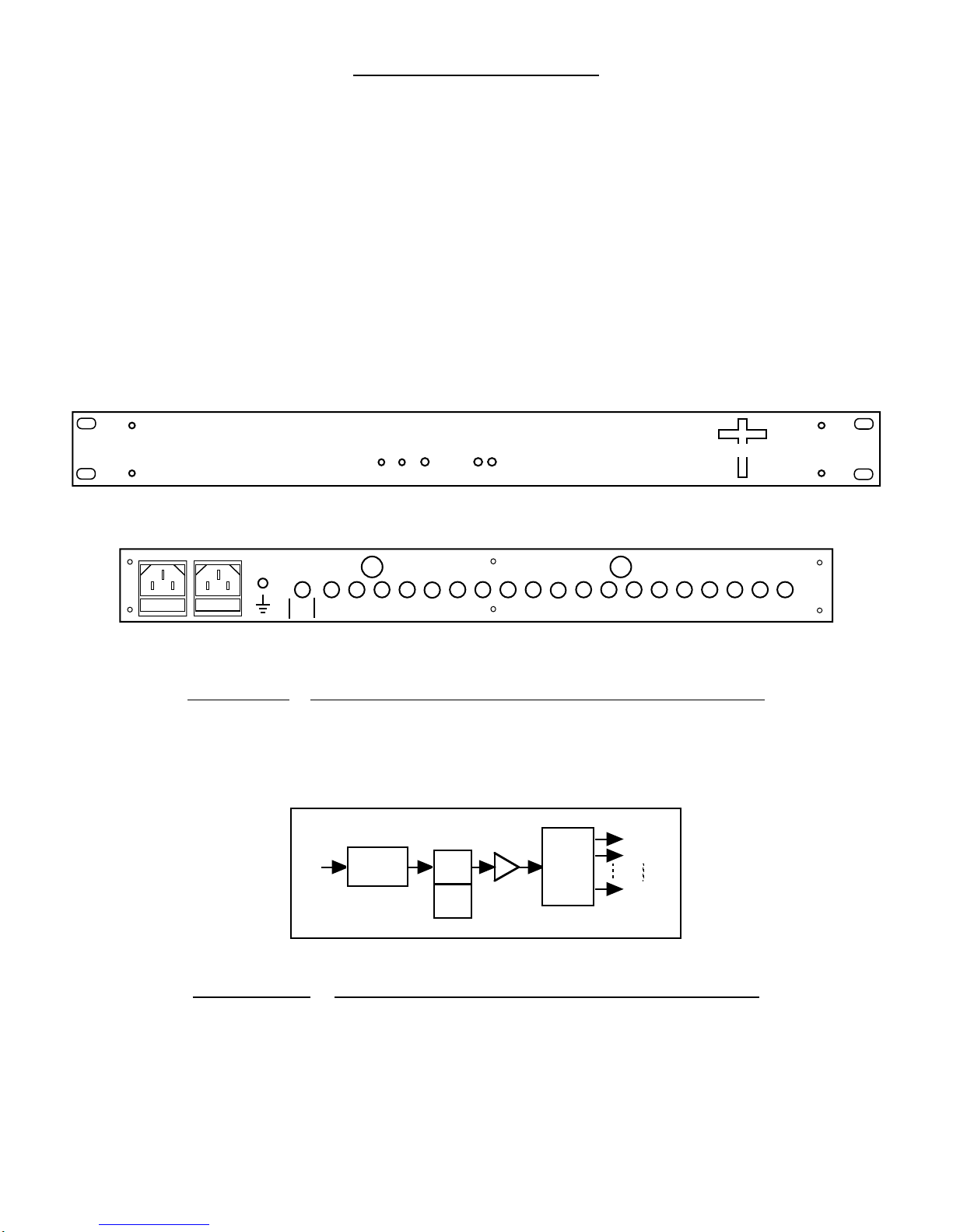
The Model 1584-116/116S* is one sixteen-way, 0.95 - 2.05 GHz, 0 dB gain splitter in a 1RU rack mount
chassis with redundant 100-240 ± 10% VAC power supplies. The splitter provides fused LNB DC power
insertion and surge protection on the RF input, and provides excellent RF characteristics. The splitter has
sixteen outputs on the back panel, and fused LNB power can be inserted on the input. Two individual 100-240
± 10% VAC input power supplies provide diode OR’d redundant power to the unit*. The LNB power line is
separately fused. A surge suppressor on the splitter input protects against high voltage transients. On the front
panel, two green LED’s indicate the presence of DC voltage from each of the two power supplies, and another
green LED indicates LNB power insertion. Two test points are also provided on the front panel to monitor the
LNB voltage. *LNB Power Insertion feature NOT available on 1584-116S model.
MODEL 1584
CROSS TECHNOLOGIES INC.
A
POWER
SPLITTER
BLNB VOLTAGE
ON
GND +DC
FRONT PANEL*
AC A AC B
GND
JI
J2J3J4
J20
J5J6J7J8J9
J10J11J12
J17 J13J14J15J16 OUT
OUTOUTOUTINOUT
OUT
OUTOUTOUT
OUT
OUT
OUT
IN OUTOUT
OUT
OUT
FUSE F1
J18
IN J19
IN
REF FUSE F2 REF
REAR PANEL*
FIGURE 1.1 MODEL 1584-116/116S FRONT AND REAR PANELS
AMP
DC
INS
SURGE
SUPPRESS
FUSE
16 WAY
SPLITTER
OUT 1
OUT 2
OUT 16
1 - 2
GHz
IN
1 - 2 GHz OUT
FIGURE 1.2 MODEL 1584-116/116S BLOCK DIAGRAM
*NOTE: Model 1584-116S has a single non-redundant, switching power supply.
1584-116 Manual Rev. G Page 3 04/23/13

1.2 Technical Characteristics
TABLE 1.0 1584-116 SPECIFICATIONS
Characteristics Specifications*
Input Characteristics
Input Impedance 75Ω(50Ω, option -D)
Return Loss 12 dB min.; 14 dB typical.
Input Level -20 dBm total maximum
Output Characteristics
Impedance 75Ω(50Ω, option -D)
Return Loss 12 dB min.; 14 dB typical.
In-Band Characteristics
Gain +0 dB ± 1.0 dB
Frequency Response ± 1.0 dB; 0.95 to 2.05 GHz
± 0.5 dB, any 20 MHz incr.
Port to Port Isolation > 18 dB, min., 20 dB typical.
Indicators
AC Power (A & B) Green LED indicates DC voltage prior to diode OR and to amplifiers
LNB DC Voltage Green LED indicates LNB power insertion on splitter input (J17)
Other LNB DC voltage 22 ± 2 VDC
Output LNB current 300 ma, max.
Surge Suppressor SiDACTOR
RF connectors Type-F, female (BNC, female - options -B and -D)
Fuses - AC 5mm, 2 amp, slow blo
Fuse - LNB Voltage 1/4”, 0.5 amp, fast blo
AC Power Redundant power supplies, 100-240 ± 10% VAC, 50 - 60 Hz, 30 watts max.
*NOTE: Model 1584-116S has a single non-redundant, switching power supply
and does NOT provide the LNB Power Insertion feature.
Mechanical 19 inch standard chassis 1.75” high X 12” deep
Options
-B BNC, 75ΩRF Connectors
-D BNC, 50ΩRF Connectors
-W9 10 MHz pass through (J17 to J16)
*+10˚C to +40˚C; Specifications subject to change without notice.
1584-116 Manual Rev. G Page 4 04/23/13
2.0 Installation
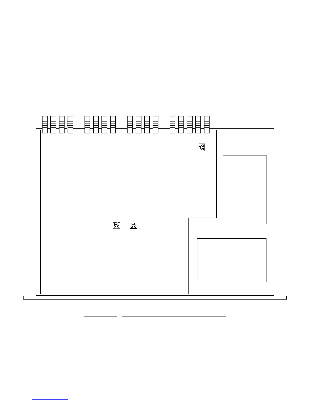
2.1 Mechanical - The 1584-116/116S consists of one RF printed circuit board (PCB) housed in a 1 RU (1.75
inch high) by 12 inch deep chassis. Redundant, switching, +24 VDC power supplies with the DC output diode
OR’d provide redundant power for the internal and external amplifiers and LEDs. (Model 1584-116S has a
single non-redundant, switching power supply). Connectors are type F, female for the RF connections (BNC,
female option -B or -D). The 1584-116/116S can be secured to a rack using the 4 holes on the front panel.
Figure 2.0 shows how the 1584-116/116S is assembled. J25 connects DC Power to the fuse as shown and J30
and J29 connect the DC voltage from the power supplies to the PCB as shown.
POWER
SUPPLY
A
2 1
J29
+24 PS IN (AC A)
PIN 1, +24 VDC
PIN 2, GROUND
POWER
SUPPLY
B
NOTE:Model 1584-
116S has a single
non-redundant,
switching power
supply
J30
+24 PS IN (AC B)
PIN 1, +24 VDC
PIN 2, GROUND
J25
LNB FUSE
PIN 1, LNB SIDE
PIN 2, +22 VDC SIDE
2 1
1
2
FIGURE 2.0 1584-116 MECHANICAL ASSEMBLY
1584-116 Manual Rev. G Page 5 04/23/13
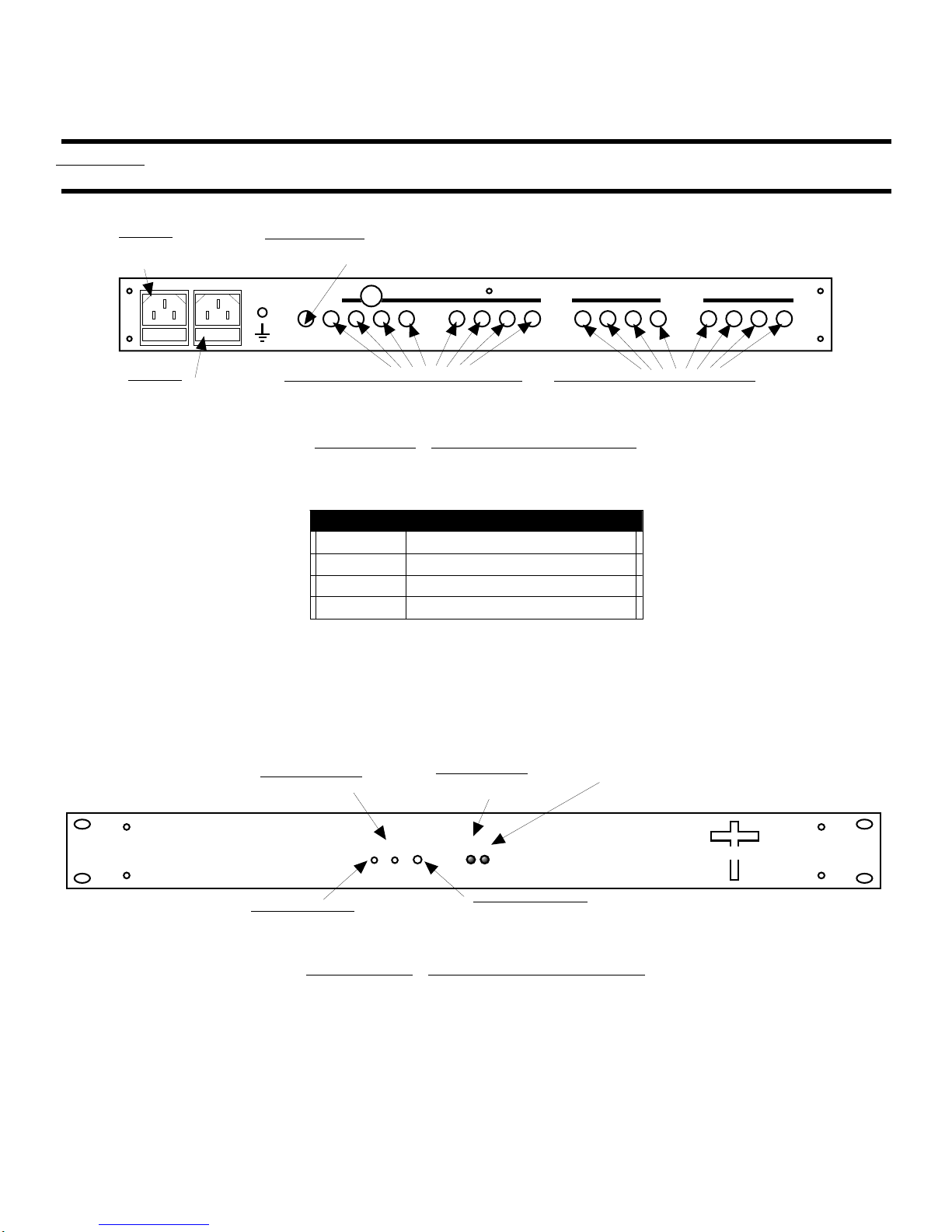
2.2 Rear Panel Input/Output Connectors
The input and output connectors on the rear panel are shown in Figure 2.1.
CAUTION! IF A FUSE IS INSTALLED IN THE FUSE F1 HOLDER, +22 VDC WILL APPEAR ON THE
SPLITTER INPUT CONNECTOR (J17) CENTER PIN.
AC A INPUT *
100-240 ±10% VAC,
47-63 HZ Uses 2 amp
Slow Blo, 5mm fuse
J17 - SPLITTER INPUT
Type F (female) 75 Ω.
See Table 2.0 for other
connector options.
J16,J15,J14,J13,J12,J11,J10,J9 - SPLITTER OUTPUTS
Type F (female) 75 Ω. Terminate when not used. See
Table 2.0 for other connector o
p
tions.
AC B INPUT
100-240 ±10% VAC,
47-63 HZ Uses 2 amp
Slow Blo, 5mm fuse
AC A AC B
GND
JI
J2J3J4J5J6J7J8J9
J10J11J12
J17 J13J14J15J16
IN
FUSE F1
SPLITTER
J8,J7,J6,J5,J4,J3,J2,J1 - SPLITTER OUTPUTS
Type F (female) 75 Ω. Terminate when not used. See
Table 2.0 for other connector o
p
tions.
FIGURE 2.1 1584-116 REAR PANEL
TABLE 2.0 RRF
2.0 RF Connector Options
Option RF Connectors
STD Type F, 75Ω
-B BNC, 75Ω
-D BNC, 50Ω
2.3 Front Panel Monitors and Indicators
Figure 2.2 shows the front panel monitors and indicators.
TP1 - +DC TEST POINT
Used to measure the LNB voltage.
+22VDC typ.
DS5 - POWER LED A
Lights green when DC
voltage is present from AC A
power supply.
TP5 - GND TEST POINT
Used to measure the LNB voltage.
DS1 - LNB VOLTAGE LED
Lights Green when LNB voltage is present
on the Splitter input (J17) center pin.
A
POWER
BLNB VOLTAGE
ON
GND +DC
MODEL 1584
SPLITTER CROSS TECHNOLOGIES INC.
FIGURE 2.2 1584-116 FRONT PANEL
*NOTE: Model 1584-116S has a single non-redundant, switching power supply.
1584-116 Manual Rev. G Page 6 04/23/13

2.4 Operation
1. Connect RF cables to the 1584-116 (See Section 2.2).
2. IF DC VOLTAGE IS REQUIRED ON THE SPLITTER RF INPUT (J17) CENTER CONDUCTOR,
install 1/4”, 0.5 amp fast blo fuses in the FUSE F1 holder
3. Connect 100-240 ± 10% VAC, 47 - 63 Hz to AC A and AC B on the back panel and observe A and B
LEDs are lit on the front panel.*
4. Monitor DC voltage to the external LNB amplifier (Front panel Green ON LED should be lit if LNB fuse
is installed in the rear panel fuse holder) to insure proper voltage.
*NOTE: Model 1584-116S has a single non-redundant, switching power supply.
CAUTION! IF A FUSE IS INSTALLED IN THE FUSE F1 HOLDER, +22 VDC WILL APPEAR ON
THE SPLITTER INPUT CONNECTOR (J17) CENTER PIN.
NOTE: FOR OPTIMUM PERFORMANCE, THE SPLITTER PORTS SHOULD BE TERMINATED
WITH 75 OHM TYPE F TERMINATION WHEN NOT USED.
AC Fuse - The fuse is a 5mm, 2 amp slow blo and is inserted in the far slot in the drawer below the AC
input as shown in Figure 2.6. There is a spare fuse in the near slot. If a fuse continues to open, the power
supply is most likely defective. Note that each power supply module within the chassis also has a fuse
but failure of this fuse indicates the power supply may be defective.
AC Fuse - 2 amp slow blow (Type T),
5 mm X 20 mm
FUSE DRAWER
SPARE FUSE
~
INPUT
100-240± 10%VA
C
47-63 Hz
2A MA
X
FUSE
TYPE T 2A GDC
250 VOLT
FOR 100 - 240 V~
~
FIGURE 2.6 FUSE LOCATION AND SPARE FUSE
1584-116 Manual Rev. G Page 7 04/23/13

2.5 Environmental Use Information
A.Rack-Mounting - To mount this equipment in a rack, please refer to the installation instructions
located in the user manual furnished by the manufacturer of your equipment rack.
B. Mechanical loading - Mounting of equipment in a rack should be such that a hazardous condition
does not exist due to uneven weight distribution.
C.Elevated operating ambient temperature - If installed in a closed or multi-unit rack assembly,
the operating ambient temperature of the rack may be greater than room ambient temperature.
Therefore, consideration should be given to Tmra.
D. Reduced air flow - Installation of the equipment in a rack should be such that the amount of air flow
required for safe operation of the equipment is not compromised. Additional space between unit
may be required.
E. Circuit Overloading - Consideration should be given to the connection of the equipment to the supply
circuit and the effect that overloading of circuits could have on over current protection and supply wiring.
Appropriate consideration of equipment name plate rating should be used, when addressing this concern.
F. Reliable Earthing - Reliable earthing of rack-mounted equipment should be maintained. Particular
attention should be given to supply connections other than direct connection to the Branch
(use of power strips).
G. Top Cover - There are no serviceable parts inside the product so, the Top Cover should not be removed.
If the Top Cover is removed the ground strap and associated screw MUST BE REINSTALLED
prior to Top Cover screw replacement. FAILURE TO DO this may cause INGRESS and/or EGRESS
emission problems.
1584-116 Manual Rev. G Page 8 04/23/13

CROSS TECHNOLOGIES, INC.
6170 Shiloh Road
Alpharetta, Georgia 30005
(770) 886-8005
FAX (770) 886-7964
Toll Free 888-900-5588
WEB www.crosstechnologies.com
E-MAIL [email protected]
Printed in USA
1584-116 Manual Rev. G Page 9 04/23/13
Table of contents
Other Cross Technologies Music Equipment manuals


Popular Music Equipment manuals by other brands


Fishman
Fishman TUNE-O-MATIC POWERBRIDGE - ROUTING Template manual

Electro-Harmonix
Electro-Harmonix HOLIEST GRAIL manual

RCF
RCF DX4008 Installation and operation manual

Mutable Instruments
Mutable Instruments Peaks user guide

MK Sound
MK Sound LFE-4 Operation manual

Soundstream
Soundstream BX-10X owner's manual