Crosswater WF6060 User manual

ILLUMINATED MIRRORS - LED
Please read these instructions carefully before starting installation and keep in a safe place for future reference.
Check the contents of the pack carefully before installation. Responsibilty will not be held for any de-fit / re-fit costs where faulty product has
been fitted. If any fault is found with materials or workmanship, it must be reported immediately to the manufacturer. Remedial action will be
taken, based on information received, on condition that: 1. Full details are supplied to the manufacturer; 2. The product has not been
modified or tampered with; 3. The manufacturer is informed of any damage/shortages prior to installation. 4. The product has not been
installed, or attempts have been made to install. We do not accept responsibility for any problems that may occur through
incorrect installation. ENSURE the room is well heated and ventilated.
Before drilling ensure there are no hidden cables or pipes(water, gas or electrical) behind hanging points. Always wear
suitable eye protection when drilling.Ensure the wall surface is able to take the weight of the complete product.
It is important to install light fittings in the correct bathroom zone i.e. the zone referred to in the IP rating of the element. This is not an
installation guide and reference should be made to the latest edition of the IET Wiring Regulations or a qualified electrician member of
NICEIC or IET.
ZONE 0 is inside the bath or shower tray itself. Any appliance used in this zone must be rated at least IP67 which is total immersion proof.
ZONE 1 is the area above the bath or shower tray to a height of 2.25m from the floor. In this zone a minimum rating of IPX4 Splash-proof
is required and elements must also be protected by a 30mA residual current device (RCD) to protect the circuit.
The electrical connection to the power supply for these appliances must be in Zones 2/3 of the bathroom in compliance with
BS 7671:2008(2011) - IET Wiring Regulations.
ZONE 2 is an area stretching 0.6m outside the perimeter of the bath and to a height of 2.25m from the floor. In this zone an IP rating of at
least IP44 is required. In addition it is good practice to consider the area around a washbasin, within a 60cm radius of any tap to be
considered as zone 2.
Appliance must also be protected by a 30mA residual current device (RCD) to protect the circuit.
Failure to have electrical products installed and certificated by a qualified electrical engineer will invalidate any product guarantee.
For full details reference should be made to the latest copy of the IET wiring regulations and all applicable British Standard and European
norm specifications.
WIRING DIAGRAM
IMPORTANT ADVICE & SAFETY - please read before installation
This product is Class I rated
and MUST be earthed.
Supply 240v/50hZ maximum
This product is IP44 rated and is suitable for installation within zone 2 above, and complies with the following safety standards:
BS EN 60598-1: 2008+A11: 2009, EN60598-2-1: 1989
LIVE
EARTH
NEUTRAL
Live supply-Red or brown
Earth supply-Green/yellow
Neutral supply-Black or blue
Live - brown
Earth -Green&yellow
Neutral - blue
1.

INSTALLATION INSTRUCTIONS
Remove all outer packing and carefully
Please do not lift the product by the plastic diffusers as this may
cause damage to your product.
check the product is in perfect condition.
The mirror is supplied with a protective film
DO NOT remove this until installation is
complete.
x6
x6
x2
IMPORTANT
The product must be installed with a minimum distance of 150mm
between the infrared sensor and an adjacent wall surface, countertop
or other object to ensure correct function of the sensor.
It is recommended that walls are fully tiled/finished before installation. This ensures that the product is installed flat to the wall face and
allows product to be easily removed if required in the future.
STEP 1
Offer the mirror up to the desired wall location considering the safety zone
requirements. Using spirit level ensure the mirror is level and upright and
mark top of mirror. Using a soft pencil mark carefully the 2 fixing points.
WF6060 X=200mm A=170mm
MEA6080 X=130mm A=410mm
MET6080 X=590mm A=35.5mm
STEP 2
Carefully drill the required holes and insert wall plugs. Prepare the power
supply. Note screws and plugs supplied are suitable for solid walls only.
ENSURE THAT THE MAINS VOLTAGE SUPPLY TO WHICH THE
MIRROR IS BEING CONNECTED IS ISOLATED
Carefully feed the mains supply cable through the rubber grommet in the
mirror frame. Hold the mirror frame in the correct position, insert screws
and screw into wall plugs, ensure they are secure and the electrical mains
supply cable free from obstruction.
2 persons
Ph2
Ø8 mm
WF6060 MET6080MEA6080
MIN
150mm
Sensor switch
Touch switch
Touch switch
2.
A
Xmm

Waste Electrical & Electronic Equipment Regulations (WEEE) requires that any electrical products showing the mark
above must not be disposed of with other household or commercial waste. To prevent possible harm to the environment or human
health from uncontrolled waste disposal, please separate any such product from other waste types and recycle it responsibly at your
local facilities. Check with your Local Authority, Recycling Center or retailer for recycling advice.
CARE & MAINTENANCE
Add sentence:
LED light strips last for thousands of hours under normal domestic use, in the unlikely event that the LED light strip shouldfail please
contact customer services for a replacement part.- write this in bold type face.
Do not strike/hit glass components with hard or pointed items. Do not place very hot or very cold items against or in close proximity to
glass surfaces unless a suitably thick insulation material is used.
The nominal thickness of the mirror glass used in this product is 5mm and is safety film backed in accordance to BS:EN6206 for your
safety. If the mirror glass becomes chipped or broken, replace immediately. For details on replacement mirror glass and other
components contact customer services.
Cleaning:
The mirror edges are treated with a specially formulated sealant designed to protect the mirror edges from contaminants and
discolouring. Failure to follow cleaning guide-lines can/will remove the benefits of the sealant.
NEVER use products containing bleach, cleaners of a gritty or abrasive nature or so called “glass and mirror” cleaning products, that
can be detrimental to the long lasting finish of the mirror.
ONLY use a clean micro fibre cloth to clean the mirror and mirror frame.
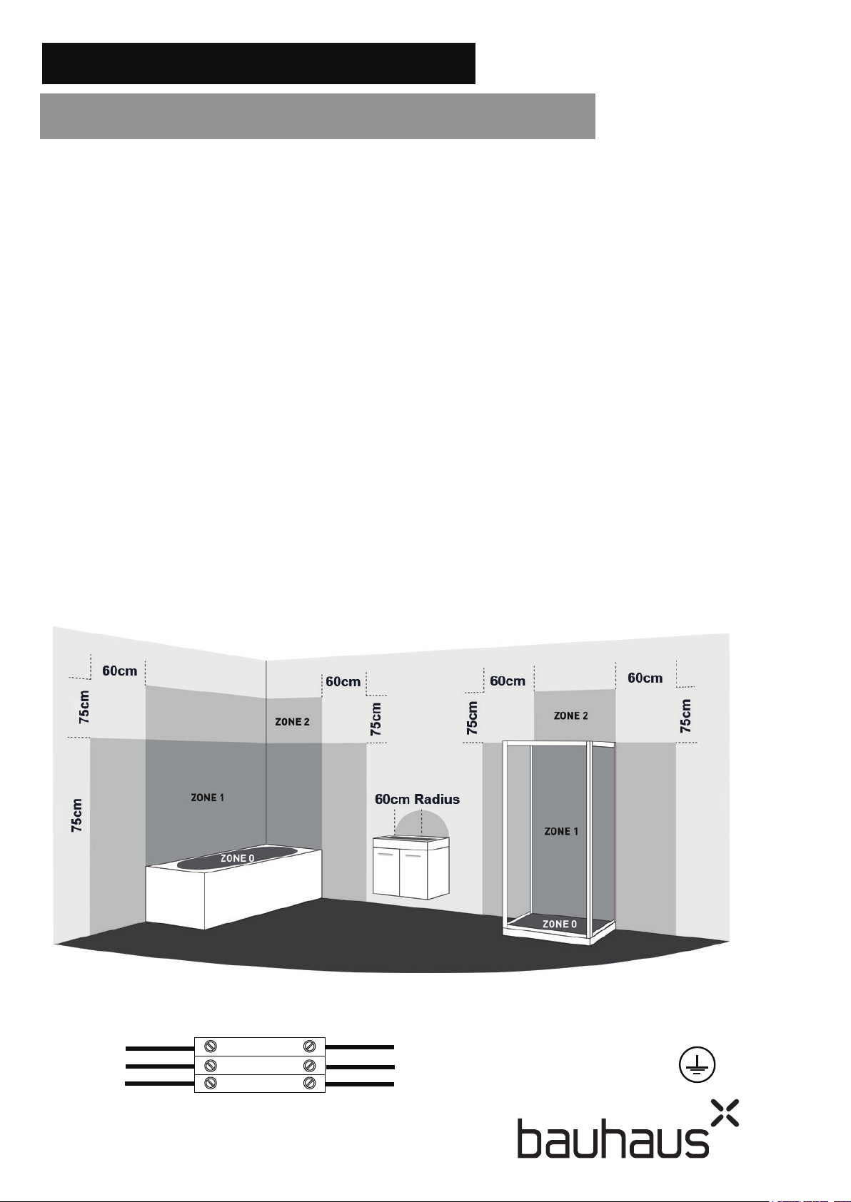
Colour Coding:
L - Live = Brown
N - Neutral = Blue
Earth = Green & Yellow
THIS PRODUCT IS MANUFACTURED TO CLASS I
CATEGORY AND MUST HAVE AN EARTH CONNECTION
Hang the mirror onto brackets.
Apply a bead of clear silicone sealant on all sides between the mirror
frame and wall surface. Allow to dry for 24 hours.
Reconnect the electrical power supply.
OPERATING INSTRUCTIONS - SEE PAGE 4
To turn the mirror lights on or off, activate the switch by passing your hand over the sensor.
Remove protective film from the mirror face, and clean as directed
below.
STEP 3
STEP 4
Tube Type
Model Led Parameter Led Driver
WF6060
69X2 Leds / 0.06W / 6400K
117 Leds / 0.06W / 6400K
312 Leds / 0.06W / 6400K / 4000K
42 Leds / 0.2W / 6400K / 4000K
15W
15W
15W
MET6080
MEA6080
Remove the cover from the electrical connection box. Using a
suitable terminal screwdriver make secure connections as follows:
Live Terminal
Connecon
Earth Terminal
Connecon
Output Wires
Neutral Terminal Connecon
3.

For any further information please contact call us on:
0345 873 8840
Or visit our web-site at:
www.bauhaus-bathrooms.co.uk
© Crosswater Copyright:
No part of this document may be reprinted or duplicated without
Crosswater Holding's consent. In the interests of continued
product development Crosswater Holdings reserves the right to
alter specification without prior notification. E & OE.
To turn illumination on touch the sensor once.
To change the colour temperature, touch and hold the
sensor until desired light temperature warm or cool is
obtained.
The colour temperature is then set until changed again.
To turn illumination on or off, wave your hand under
the sensor switch located at the bottom of the mirror.
The heated pad will operate when the light is illuminated;
The heat pad will work if the mirror lamp(s) expire.
Once turned on the heating pad will warm the mirror and
clear the surface of condensation.
A
++
A
+
A
B
C
D
E
L
E
D
LED
Mirror
This luminaire
contains built-in
LED light strips
The lamps cannot be changed
in the luminaire.
874/2012
Energy label
4.
This manual suits for next models
2
Other Crosswater Personal Care Product manuals