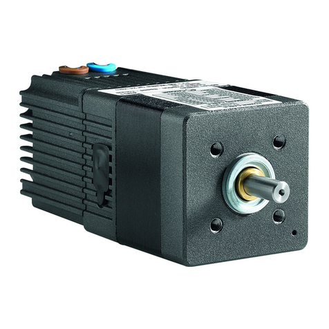
Crouzet SMI21 Series User manual

SMI21 & SMI22 CANopen
C.MO.SAV.00019.FR_V2 Page 1/20
April 27th, 2018
SAFETY USER MANUAL
CROUZET Motors
Important Notes
This manual is part of the product.
Read and follow the instructions in this manual.
Keep this manual in a safe place.
Give this manual and any other documents relating to the product to anyone that uses the product.
Read and be sure to comply with all the safety instructions and the section "Before you Begin -
Safety-Related Information".
Please consult the latest catalogue to find out about the product's technical specifications.
We reserve the right to make modifications without prior notification.

SMI21 & SMI22 CANopen
C.MO.SAV.00019.FR_V2 Page 2/20
April 27th, 2018
Table of Contents
1. Before you Begin - Safety-Related Information.........................................................................................4
1.1. Personnel Qualifications ...................................................................................................................4
1.2. Use in Compliance with Industry Practice.........................................................................................4
1.3. Basic Information ..............................................................................................................................5
1.4. Standards and concepts ...................................................................................................................6
2. Precautions for use concerning the mechanics.........................................................................................7
2.1. Data specific to the motor shaft ........................................................................................................7
3. Installation..................................................................................................................................................8
3.1. Overview of the Installation Procedure ...........................................................................................10
3.2. Electromagnetic Compatibility (EMC) .............................................................................................10
3.3. Prior to Mounting.............................................................................................................................11
3.4. Mounting the Motor .........................................................................................................................12
3.5. Electrical Installation .......................................................................................................................13
3.6. Connecting the Holding Brake (Optional) .......................................................................................15
4. Operation.................................................................................................................................................16
4.1. Preparation for Operating................................................................................................................16
5. Diagnostics and Troubleshooting ............................................................................................................18
5.1. Mechanical Failures ........................................................................................................................18
5.2. Electrical Failures............................................................................................................................18
6. Service, maintenance and disposal.........................................................................................................19
6.1. Addresses of After-Sales Service Outlets.......................................................................................19
6.2. Storage............................................................................................................................................19
6.3. Maintenance....................................................................................................................................19
6.4. Replacing the Motor........................................................................................................................20
6.5. Dispatch, Storage, Disposal............................................................................................................20

SMI21 & SMI22 CANopen
C.MO.SAV.00019.FR_V2 Page 3/20
April 27th, 2018
About This Manual
This manual applies to SMI21 DCmind brushless products:
80140301 SMI21,
80180301 SMI21,
80280302 SMI21,
And SMI22 DCmind Brushless products:
8035xxxx SMI22,
8036xxxx SMI22,
8037xxxx SMI22,
Reference source for manuals
The manuals can be downloaded from our website at the following address:
http://www.crouzet-motors.com/
Units
SI units are the default values.
Risk Categories
In this manual, safety instructions are identified by warning symbols.
Depending on how serious the situation is, the safety instructions are split into 3 risk categories.
DANGER
DANGER indicates a directly dangerous situation which, if the
instructions are not followed, will inevitably lead to a serious or fatal
accident.
WARNING
WARNING indicates a possibly dangerous situation which, if the
instructions are not followed, will in some cases lead to a serious or
fatal accident or cause damage to equipment.
CAUTION
CAUTION indicates a potentially dangerous situation which, if the
instructions are not followed, will in some cases lead to an accident or
cause damage to equipment.

SMI21 & SMI22 CANopen
C.MO.SAV.00019.FR_V2 Page 4/20
April 27th, 2018
1. BEFORE YOU BEGIN - SAFETY-RELATED INFORMATION
1.1.Personnel Qualifications
Only qualified personnel who are familiar with and fully understand the contents of this manual are
authorized to work on and with this product.
Qualified personnel must be familiar with current standards, regulations and requirements concerning
prevention of accidents during work undertaken on and with this product.
These qualified personnel must have undergone safety training in order to be able to detect and avoid
related hazards.
Their professional training, knowledge and experience renders such qualified personnel capable of
preventing and recognizing potential hazards that might be generated through use of the product, modifying
settings and the mechanical, electrical and electronic equipment in the whole installation.
1.2.Use in Compliance with Industry Practice
As demonstrated in these instructions, this product is a component designed for use in industrial
environments.
The current safety instructions, specified conditions and technical specifications must be complied with at all
times.
Before starting to use the product, undertake a risk analysis using actual examples. Depending on the result,
the necessary safety measures must be implemented.
Since the product is used as a component in an overall system, it is the user's responsibility to guarantee
people's safety through the concept of the overall system (e.g. concept of a machine).
Only use original manufacturer accessories and spare parts.
The product must not be used in explosive atmospheres (Ex zone).
All other types of use are deemed to be non-compliant and can be dangerous.
Only qualified personnel are authorized to install, operate, maintain and repair electrical equipment.

SMI21 & SMI22 CANopen
C.MO.SAV.00019.FR_V2 Page 5/20
April 27th, 2018
1.3.Basic Information
DANGER
DANGEROUS PHENOMENON LINKED TO ELECTRIC SHOCK, EXPLOSION OR
EXPLOSION DUE TO AN ELECTRIC ARC
• Only qualified personnel who are familiar with and fully understand the contents of
this manual are authorized to work on this product. Only qualified personnel are
authorized to undertake installation, setting, repair and maintenance.
• The installation manufacturer is responsible for complying with all the applicable
requirements and regulations with regard to grounding the drive system.
• It is the user's responsibility to define whether it is necessary to ground the motor,
depending on its intended use.
• Do not touch unprotected live parts.
• Only use electrically-isolated tools.
• AC voltages can be connected to unused conductors in the motor cable. Isolate
unused conductors at both ends of the motor cable.
• The motor produces a voltage when the shaft turns. Protect the motor shaft from
any external drive operation before working on the drive system:
–De-energize all connections.
–Attach a notice saying "DO NOT START UP" on all the switches.
–Protect all the switches from switching on.
–Wait for the internal motor capacitors to discharge. Measure the voltage on the
power cable and check that it is less than 12 VDC.
• Install protective covers and ensure they are closed before energization.
Failure to comply with these precautions will result in death or serious injury.
WARNING
LOSS OF COMMAND CONTROL
• When perfecting the command concept, the installation manufacturer must take
account of the possibilities for potential failure of command paths and provide, for
certain critical functions, the means of returning to safe states during and after the
failure of a command path.
Examples of critical command functions are:
EMERGENCY STOP, end position limiting, network outage and restarting.
• Separate or redundant command paths must be available for critical functions.
• Comply with the accident prevention instructions and all current safety directives.
• Any installation in which the product described in this manual has a central role
must be carefully and meticulously checked prior to commissioning to ensure it is
working properly.
Failure to comply with these precautions can result in death or serious injury.
WARNING
UNBRAKED MOVEMENT
In the event of a power outage and errors resulting in disconnection of the power
stage, the motor is no longer braked in a controlled way and can cause damage.
• Prevent access to the hazardous zone.
• If necessary, use a damped mechanical stop or a service brake.
Failure to comply with these precautions can result in death, serious injury or
damage to equipment.

SMI21 & SMI22 CANopen
C.MO.SAV.00019.FR_V2 Page 6/20
April 27th, 2018
1.4.Standards and concepts
The product is ROHS and REACH confirmed following European Directive 2011/65/CE. Following this
confirmation, the product is CE marked.
The electrical design follows the IEC 60335-1 and IEC 60950-1 standards.

SMI21 & SMI22 CANopen
C.MO.SAV.00019.FR_V2 Page 7/20
April 27th, 2018
2. PRECAUTIONS FOR USE CONCERNING THE MECHANICS
2.1.Data specific to the motor shaft
WARNING
MOTOR MECHANISM
Exceeding the maximum permissible forces on the shaft leads to rapid
bearing wear, a broken shaft or damage to any accessories (encoder,
brake, etc.)
• Never exceed the maximum axial and radial forces.
• Protect the shaft from any impact.
• When press-fitting components, do not exceed the maximum
permissible axial force.
Failure to comply with these precautions can result in death,
serious injury or damage to equipment.
The maximum press-fit force is limited by the maximum permissible axial force on the ball bearings.
This maximum axial force is stated in the motor technical data sheet.
Alternatively, the component to be fixed in position can be clamped, glued or shrunk-fit.

SMI21 & SMI22 CANopen
C.MO.SAV.00019.FR_V2 Page 8/20
April 27th, 2018
3. INSTALLATION
Installation must, as a general rule, be performed in accordance with good practice.
WARNING
HEAVY WEIGHT AND FALLING PARTS
The motor can be extremely heavy.
• When mounting, take the weight of the motor into account.
•Mounting (screw tightening torque) must be performed in such a way
that the motor cannot become detached, even if subjected to strong
accelerations or constant jolting.
Failure to comply with these precautions can result in death,
serious injury or damage to equipment.
WARNING
STRONG ELECTROMAGNETIC FIELDS
Motors can generate locally powerful electrical and magnetic fields.
These can cause sensitive equipment to fail.
• Keep people with implants such as pacemakers away from the
motor.
• Do not place sensitive equipment in the immediate vicinity of the
motor.
Failure to comply with these precautions can result in death,
serious injury or damage to equipment.
WARNING
UNEXPECTED BEHAVIOR CAUSED BY DAMAGE OR FOREIGN BODIES
Following damage to the product or the presence of foreign bodies,
deposits or penetration of fluid, unexpected behavior can occur.
• Do not use damaged products.
• Make sure that no foreign body has been able to penetrate the
product.
• Check that the power supply lead seals and cable entries have been
positioned correctly.
• Check that the stopper protecting the USB B to USB A micro
connector has been positioned correctly.
Failure to comply with these precautions can result in death,
serious injury or damage to equipment.

SMI21 & SMI22 CANopen
C.MO.SAV.00019.FR_V2 Page 9/20
April 27th, 2018
WARNING
HOT SURFACES
The product's metal surface can heat up to more than 70°C in certain
types of use.
• Avoid all contact with the metal surface.
• Do not place flammable or heat-sensitive components in the
immediate vicinity.
• Assemble components in the best way for heat dissipation.
Failure to comply with these precautions can result in injury or
damage to equipment.
WARNING
DAMAGE AND DESTRUCTION OF THE MOTOR CAUSED BY STRESS
The motor is not designed to carry loads. If subjected to stress, the
motor can be damaged, or even fall.
• Do not use the motor as a step.
• Prevent the motor from being used in any way other than its intended
purpose by installing guards or displaying safety instructions.
Failure to comply with these precautions can result in injury or
damage to equipment.
CAUTION
VOLTAGE SURGES
During braking phases, the motor generates voltage surges.
• Check that these voltage surges are acceptable to other devices
connected on the same power supply.
• If possible, use an external circuit to limit voltage surges.
if the brake is used intensively.
Failure to comply with these precautions can result in injury or
damage to equipment.

SMI21 & SMI22 CANopen
C.MO.SAV.00019.FR_V2 Page 10/20
April 27th, 2018
3.1.Overview of the Installation Procedure
The installation procedure is described in the following sections:
Electromagnetic Compatibility (EMC)
Prior to Mounting
Mounting the Motor
Electrical Installation
Connecting the holding brake (optional)
Check that these sections have been read and understood, and that installation has subsequently been
executed correctly.
3.2.Electromagnetic Compatibility (EMC)
DANGER
INTERFERENCE AFFECTING SIGNALS AND EQUIPMENT
Disturbed signals can cause equipment to behave unpredictably.
• Wire up products in compliance with the specific EMC
recommendations for each device.
• Make sure that these EMC recommendations are executed correctly.
Failure to comply with these precautions can result in death,
serious injury or damage to equipment.
Recommendations in terms of EMC: Installing the motor power supply leads
When planning the wiring, take account of the fact that the motor power supply leads must be kept separate
from line supplies or cables carrying signals.
Comply with the following measures as concerns EMC.
Measures relating to EMC
Effect
Keep the cables as short as possible.
Do not install unnecessary cable loops.
Reduces stray couplings, both capacitive and
inductive.
Ground the product.
Reduces emissions, improves immunity to
interference.
If using shielded cables, install the cable
shielding so that it is in contact with the widest
possible surface area, use cable grips and
ground strips.
Reduces emissions.
Keep the motor power supply leads separate
from cables carrying signals or use shielding
plates.
Reduces stray cross-couplings.
If using shielded cables, install the cables without
any disconnection points. 1)
Reduces stray radiation.
1) When a cable is disconnected for installation, the cables must be connected at the disconnection point via a shelding
connection and a metal box.
Equipotential bonding conductors
If using shielded cables, differences in potential can generate unauthorized currents on the cable shielding.
Use equipotential bonding conductors to minimize currents on the cable shielding.

SMI21 & SMI22 CANopen
C.MO.SAV.00019.FR_V2 Page 11/20
April 27th, 2018
3.3.Prior to Mounting
Look for any damage
Damaged drive systems must neither be mounted nor used.
Check the drive system prior to mounting, looking out for any visible signs of damage.
Clean the shaft
On leaving the factory, the motor shaft extensions are coated with a film of oil.
If transmission devices are to be glued on, it may be necessary to remove the film of oil and clean the shaft.
If necessary, use degreasing products in accordance with the glue manufacturer's instructions.
Avoid any direct contact between the skin or sealing materials and the cleaning product used.
Flange mounting surface
The mounting surface must be stable, flat and clean.
In regards to installation, make sure that all dimensions and tolerances are respected.
Specification of power supply leads
The power supply leads for the motor and its accessories must be selected carefully on the basis of their
length, the motor supply voltage, the ambient temperature, the current level circulating therein, and their
environment.
WARNING
DAMAGE AND FIRE DUE TO INCORRECT INSTALLATION
Repeated force and movement around the grommets can damage the
cables.
• Comply with the stated bend radius.
• Avoid subjecting the grommets to repeated force or movement.
• Attach the power supply cables close to the grommets using a strain
relief.
Failure to comply with these precautions can result in injury or
damage to equipment.

SMI21 & SMI22 CANopen
C.MO.SAV.00019.FR_V2 Page 12/20
April 27th, 2018
3.4.Mounting the Motor
DANGER
HOT SURFACES
The motor's surface can heat up to more than 70°C in certain types of
use.
• Avoid contact with hot surfaces.
• Do not place flammable or heat-sensitive components in the
immediate vicinity.
• Assemble components in the best way for heat dissipation.
• Check the temperature when performing a test.
Failure to comply with these precautions can result in injury or
damage to equipment.
WARNING
UNEXPECTED MOVEMENT DUE TO ELECTROSTATIC DISCHARGES
Electrostatic discharges (ESD) on the shaft can, in rare cases, lead to
encoder system failures and generate unexpected motor movements.
• Use conductive parts (e.g. antistatic straps) or other appropriate
measures to avoid a static charge due to movement.
Failure to comply with these precautions can result in death,
serious injury or damage to equipment.
WARNING
UNINTENDED BEHAVIOR CAUSED BY MECHANICAL DAMAGE TO THE
MOTOR
Exceeding the maximum permissible forces leads to rapid bearing
wear, a broken shaft or damage to the internal encoder.
• Never exceed the maximum axial and radial forces.
• Protect the shaft from any impact.
• When press-fitting components, do not exceed the maximum
permissible axial force.
Failure to comply with these precautions can result in death,
serious injury or damage to equipment.
Mounting position
The motor can be mounted in any position.
Mounting
When mounting the motor on the flange, the motor must be aligned precisely in both the axial and radial
directions. All the fixing screws must be tightened to the tightening torque stipulated by the application,
taking care not to generate any warping.
Install the transmission devices
If the transmission device is installed incorrectly, this can damage the motor.
Transmission devices such as pulleys and gears must be mounted in compliance with the maximum axial
and radial loads defined in each motor's technical data sheet.
Follow the transmission device manufacturer's assembly instructions.
The motor and the transmission device must be aligned precisely both axially and radially. If this is not done,
it will result in abnormal operation, damage to the bearings and significant wear.

SMI21 & SMI22 CANopen
C.MO.SAV.00019.FR_V2 Page 13/20
April 27th, 2018
3.5.Electrical Installation
These motors are not designed to be connected directly to the line supply.
It is the installer's responsibility to define the electrical protection devices to be implemented according to the
regulations applicable to the end product range of application.
For the power supply to the power part we recommend using a double-insulated stabilized power supply.
The motor is not protected against polarity reversals on the power part.
The motor is regenerative, in other words it can feed back energy to the power supply during braking
phases. Voltage surges created in this way can reach levels that risk destroying the motor itself or devices
placed on the same power supply.
DANGER
ELECTRIC SHOCK
High voltages can appear unexpectedly on the motor connection.
• The motor produces a voltage when the shaft turns. Protect the
motor shaft from any external drive operation before working on the
drive system.
• The system manufacturer is responsible for complying with all
applicable regulations with regard to grounding the drive system.
Failure to comply with these precautions will result in death or
serious injury.
WARNING
UNEXPECTED MOVEMENT
As a result of incorrect wiring or other error, the drives can execute
unexpected movements.
• Do not start up the installation if there is anybody or any obstacle
in the danger zone.
• Execute the initial test movements without loads connected.
• Do not touch the motor shaft or related drive elements.
Failure to comply with these precautions can result in death,
serious injury or damage to equipment.

SMI21 & SMI22 CANopen
C.MO.SAV.00019.FR_V2 Page 14/20
April 27th, 2018
WARNING
VOLTAGE SURGES
During braking phases, the motor generates voltage surges.
• Check that these voltage surges are acceptable to other devices
connected on the same power supply.
• If possible, use an external circuit to limit voltage surges.
if the brake is used intensively.
Failure to comply with these precautions can result in death,
serious injury or damage to equipment.
CAUTION
FIRE CAUSED BY BAD CONTACTS
If the connector is not properly inserted the motor connector can
overheat, causing the contacts to melt due to an electric arc.
• Incorrect connection can cause overheating due to an electric arc.
Failure to comply with these precautions can result in injury or
damage to equipment.
CAUTION
IRREPARABLE PRODUCT DAMAGE CAUSED BY REVERSED POLARITY
Incorrect connection of the power can result in reversed polarity,
resulting in destruction of the circuit board inside the motor.
• Check the conformity of the power connections.
• Place a slow-blow fuse on the power supply that is appropriately
sized for the current the motor needs to absorb in the application.
Failure to comply with these precautions can result in injury or
damage to equipment.
Connecting the protection conductor
It is the installer's responsibility to define whether the motor needs to be grounded.
The mounting flange should be used for this purpose.
Never connect or disconnect the product power supply leads while the voltage is applied.

SMI21 & SMI22 CANopen
C.MO.SAV.00019.FR_V2 Page 15/20
April 27th, 2018
3.6.Connecting the Holding Brake (Optional)
WARNING
LOSS OF BRAKING FORCE DUE TO WEAR OR HIGH TEMPERATURE
Engaging the holding brake while the motor is running leads to rapid
wear and loss of braking force.
• Do not use the brake as a service brake.
• Note that "emergency stops" can also cause wear.
Failure to comply with these precautions can result in death,
serious injury or damage to equipment.
WARNING
UNEXPECTED MOVEMENT
Releasing the holding brake can result in unexpected movement on
the installation.
• Make sure this cannot cause any damage.
• Do not continue with the test if there is anybody or any obstacle in
the danger zone.
Failure to comply with these precautions can result in death,
serious injury or damage to equipment.
CAUTION
MALFUNCTION OF THE HOLDING BRAKE DUE TO INAPPROPRIATE
VOLTAGE
• If the voltage is too low, the holding brake cannot release, resulting in
wear.
• In the event of voltages higher than the specified value, the holding
brake will be subject to significant overheating.
Failure to comply with these precautions can result in injury or
damage to equipment.
A motor with a holding brake needs a corresponding control logic which releases the holding brake at the
start of the rotation movement, locking the motor shaft in time when the motor stops.

SMI21 & SMI22 CANopen
C.MO.SAV.00019.FR_V2 Page 16/20
April 27th, 2018
4. OPERATION
4.1.Preparation for Operating
Prior to operating:
Check that the mechanical installation is correct.
Check that the electrical installation has been carried out professionally: pay special attention to the
protective conductor connections and the grounding connections. Check that all the junctions are
correct, properly connected and that the screws are fully tightened.
Check the ambient conditions and operating conditions: make sure that the stipulated ambient conditions
are adhered to and that the drive solution conforms to the expected operating conditions.
Check that any transmission devices that are already mounted are balanced and aligned precisely.
Check that the operating conditions do not generate abnormal voltage surges for the product or the
application.
Check that the holding brake can withstand the maximum load. After applying the braking voltage, make
sure that the holding brake is fully released. Make sure that the holding brake is fully released before
initiating a movement.
WARNING
UNEXPECTED MOVEMENT
As a result of incorrect wiring or other error, the drives can execute
unexpected movements.
• Check the wiring.
• Do not start up the installation if there is anybody or any obstacle in
the danger zone.
• Execute the initial test movements without loads connected.
• Do not touch the motor shaft or related drive elements.
Failure to comply with these precautions can result in death,
serious injury or damage to equipment.
WARNING
ROTATING PARTS
Rotating parts can cause injuries, trap clothing or hair. Separate parts
or unbalanced parts can be ejected.
• Check that all rotating parts are fitted properly.
• Use a protective cover for rotating parts.
Failure to comply with these precautions can result in death,
serious injury or damage to equipment.
WARNING
FALLING PARTS
The motor can move due to the reaction torque; it can topple over and
fall.
• Fix the motor firmly in place so that it cannot become detached
during rapid acceleration.
Failure to comply with these precautions can result in death,
serious injury or damage to equipment.

SMI21 & SMI22 CANopen
C.MO.SAV.00019.FR_V2 Page 17/20
April 27th, 2018
CAUTION
HOT SURFACES
The motor's surface can heat up to more than 70°C in certain types of
use.
• Avoid contact with hot surfaces.
• Do not place flammable or heat-sensitive components in the
immediate vicinity.
• Assemble components in the best way for heat dissipation.
• Check the temperature when performing a test.
Failure to comply with these precautions can result in injury or
damage to equipment.
CAUTION
VOLTAGE SURGES
During braking phases, the motor generates voltage surges.
• Check that these voltage surges are acceptable to other devices
connected on the same power supply.
• If possible, use an external circuit to limit voltage surges.
if the brake is used intensively.
Failure to comply with these precautions can result in injury or
damage to equipment.

SMI21 & SMI22 CANopen
C.MO.SAV.00019.FR_V2 Page 18/20
April 27th, 2018
5. DIAGNOSTICS AND TROUBLESHOOTING
5.1.Mechanical Failures
Error
Cause
Remedy
Significant temperature rise
Overload
Holding brake not released
Reduce the load
Check control of the holding brake
Whistling or knocking
Faulty bearings
Contact the after-sales service
Friction noise
A rotary transmission device is catching
Align the transmission device
Radial vibration
Transmission device incorrectly aligned
Transmission device unbalanced
Twisted shaft
Resonance in the fixing
Align the transmission device
Balance the transmission device
Contact the after-sales service
Check the rigidity of the motor fixing
Axial vibration
Transmission device incorrectly aligned
Transmission device being knocked
Resonance in the fixing
Align the transmission device
Check the transmission device
Check the rigidity of the motor fixing
5.2.Electrical Failures
Error
Cause
Remedy
The motor does not start or
starts with difficulty
Overload
Fault in the connection wires
Reduce the load
Check the connection wires
Contact the after-sales service
Significant temperature rise in
the stator
Overload
Reduce the load
Temperature rise in the
connection terminals
Power supply wires disconnected or
loose
Tighten the screws

SMI21 & SMI22 CANopen
C.MO.SAV.00019.FR_V2 Page 19/20
April 27th, 2018
6. SERVICE, MAINTENANCE AND DISPOSAL
6.1.Addresses of After-Sales Service Outlets
Please contact your distributor.
The list of distributors is accessible on the CROUZET Automatismes website www.crouzet-motors.com
6.2.Storage
The motors must only be transported and stored in dry, dust-free environments that are resistant to vibration.
The ambient conditions are stated in the product technical data sheet and must be adhered to.
The storage period is essentially dictated by the stability of the lubricants and should be less than 36 months.
To keep the motor in working order, it is advisable to start up the drive solution occasionally.
6.3.Maintenance
Only the manufacturer is authorized to undertake repairs. Any personal intervention voids any guarantee and
precludes manufacturer liability.
Repairs cannot be performed with the motor mounted.
Prior to any intervention on the drive system, please refer to the Installation and Commissioning
sections to find out what steps to take.
We recommend that the following operations are done at regular intervals.
Connections and fixing
=> Check the connection cables and connections regularly for signs of damage. Replace any damaged
cables immediately.
=> Check that all the transmission devices are fully tightened.
=> Retighten all the mechanical and electrical bolted connections to the appropriate tightening torque.
WARNING
UNEXPECTED MOVEMENT
Exceeding the permissible ambient conditions can allow foreign bodies
from the surrounding area to get in and lead to unexpected motor
movements or damage to equipment.
• Check the ambient conditions.
• It is vital to avoid fluid stagnation in the shaft bushing.
Failure to comply with these precautions can result in death,
serious injury or damage to equipment.
Cleaning
Clean the motor regularly to remove any dust and dirt. If heat cannot dissipate adequately into the ambient
air, this can cause abnormally high temperatures.
The motors are not designed to be cleaned with high-pressure washers. Jet washing can cause water to get
inside the motor.
When using cleaning products or solvents, take care not to damage the motor power supply leads and any
options (brake), ball bearings and the motor coating.

SMI21 & SMI22 CANopen
C.MO.SAV.00019.FR_V2 Page 20/20
April 27th, 2018
Check/run in the holding brake
Occasional braking with a shifted load helps conserve the holding brake's holding torque. If the holding brake
produces no mechanical work over a prolonged period (braking with a shifted load), some parts of the
holding brake can corrode or other deposits can accumulate and thus reduce the holding torque.
The holding brake has been run in on leaving the factory. If the holding brake produces no mechanical work
over a prolonged period, some parts of the holding brake can corrode. If the holding brake should not
demonstrate the holding torque specified in the technical specifications, it would need to be run in again:
=> The motor is not mounted. The holding brake is engaged.
=> Measure the brake holding torque using a torque wrench.
=> Compare the value with the holding torque indicated on the technical data sheet.
=> If the holding torque is markedly different from the stated values, turn the motor shaft by hand 25 turns in
both directions.
=> Repeat the operation. If the holding torque has not been restored after 3 repeat operations, please
contact your vendor.
6.4.Replacing the Motor
=> Disconnect all the supply voltages. Make sure that no other voltage is applied (safety instructions).
=> Mark all connections and demount the product.
=> Replace it with a motor with the same part number.
=> Install the new product as described in section 3 "Installation".
6.5.Dispatch, Storage, Disposal
Dispatch
Protect the product against shocks during transport.
Use the original packaging for this purpose.
Storage
Only store the product in the stated permissible ambient conditions in terms of temperature and air humidity.
Protect the product against dust and dirt.
Disposal
The product is made up of various materials that can be reused or are suitable for separation and recycling.
Dispose of the product in accordance with local regulations.
Other manuals for SMI21 Series
1
This manual suits for next models
7
Table of contents
Other Crouzet Engine manuals
