Crown PIP-FTE User manual

125512-1
11/97
Printed on
recycled paper.
© 1997 by Crown International, Inc., P.O. Box 1000, Elkhart, IN 46515-1000
U.S.A. Telephone: 219-294-8000. Fax: 219-294-8329.
P.I.P.
modules are
produced by the Professional Audio Division of Crown International, Inc.
Trademark Notice:
Crown
®,
Macro-Tech
®,
Com-Tech
®,
IOC
®and
P.I.P.
®are
registered trademarks of Crown International, Inc. Other trademarks are the
property of their respective owners.
P.I.P.–FTE
P.I.P.- FTE
CH 2 CH 1
+–
BALANCED INPUTS
+ = NON-INVERTING
– = INVERTING
+–
—CAUTION—
DO NOT USE AMPLIFIER PHONE JACKS
WITH THIS MODULE PLUGGED IN.

P.I.P.–FTE
Page 2

P.I.P.–FTE
Page 3
1 Welcome
Thank you for purchasing the
Crown P.I.P.-FTE accessory.
P.I.P.
®modules are designed to
quicklyinstallintherearpanelof
many Crown amplifiers.
P.I.P.
stands for “Programmable Input
Processor.” Their versatile fea-
tures expand the capabilities of
your amplifier and enable you to
customize it for your particular
needs.
TheP.I.P-FTEemploysbalanced
transformerstoisolatetheinputs
of
Com-Tech
®or
Macro-Tech
®
seriesamplifiers.Thisaddsvalu-
able isolation from shorted input
cables, faulty wiring and com-
mon mode noise.
In addition to transformer isola-
tion, this
P.I.P.
provides two im-
portant filters to attenuate un-
wanted ultrasonic and subsonic
frequencies.
Ahornequalizationcircuitisalso
available to compensate for the
high-frequency roll-off of con-
stant-directivity horns.
Youshouldfindtheseitemswhen
you unpack:
• P.I.P.-FTE module
• Two 8-32 Phillips Machine
Screws
• Two Lock Washers
• Two Quick-Connect Barrier
Blocks
• This Owner’s Manual
Features
❏Balanced inputs with 1:1 iso-
lation transformers to help
keep the input noise-free.
❏RFI filter which attenuates un-
wanted ultrasonic frequencies
that would otherwise waste am-
plifierpower. TheRFIfilterisa12
dB/octave (2nd order), Bessel-
tuned low-pass filter with a 3 dB
roll-off point at 33 kHz.
❏Switchable subsonic/bass fil-
ter with 50-, 100- or 300-Hz
roll-off frequencies.
❏Constant-directivity horn
equalization network which
can be switched on or off.
❏Quick-connect barrier block
connectors provide greater
wiring flexibility and make in-
stallation easier.
P.I.P.- FTE
CH 2 CH 1
+–
BALANCED INPUTS
+ = NON-INVERTING
– = INVERTING
+–
—CAUTION—
DO NOT USE AMPLIFIER PHONE JACKS
WITH THIS MODULE PLUGGED IN.
Fig. 1.1 P.I.P.-FTE

P.I.P.–FTE
Page 4
2 Facilities2 Facilities
2 Facilities
A. Balanced Input
Withthesespecialquick-connect
barrier-block connectors (Figure
2.1), it’s quick and easy to attach
each input cable with just three
screws. Once the cable is at-
tached, the connector can be
quicklyunpluggedand,ifdesired,
moved to a different amplifier.
B. Subsonic/Bass Switch
A 4-position sliding switch is pro-
vided for each channel to control
the subsonic/bass filter. This filter
is an 18-dB/octave (3rd order)
Butterworth high-pass filter which
can be selected to attenuate low
frequenciesbelow50Hz,100Hzor
300 Hz. It can also be switched off
(Flat). A label on the side of each
switchidentifiestheswitchsettings.
C. Constant-Directivity
Horn Equalization Jumper
A jumper is provided for each
channeltoenable/disablethecon-
stant-directivityhornequalization.
The jumper for channel 1 (J1) is
shown in the “OFF” position while
the jumper for channel 2 (J2) is
shown in the “ON” position. The
constant directivity horn equaliza-
tion is a 6-dB/octave shelving net-
workwitha3dBriseat3.2kHzand
a peak boost of 12.5 dB at 24 kHz.
A
P.I.P.- FTE
CH 2 CH 1
+–
BALANCED INPUTS
+ = NON-INVERTING
– = INVERTING
+–
—CAUTION—
DO NOT USE AMPLIFIER PHONE JACKS
WITH THIS MODULE PLUGGED IN.
CB B
S2 S1
J2 J1
FLAT
50 Hz
100 Hz
300 Hz
FLAT
50 Hz
100 Hz
300 Hz
ON
OFF
Front View
Bottom View
Fig. 2.1 Facilities

P.I.P.–FTE
Page 5
Fig. 3.1 Constant-
Directivity Horn
Equalization (with
RFI filter)
3 Installation
Before installing this
P.I.P.
mod-
ule, you’ll want to configure it to
best serve your needs.
Note:
The RFI filter is always on
and cannot be switched off.
1. Adjusttheconstant-directivity
equalization jumper of each
channel to be either “ON” or
“OFF”(seeFigure2.1).Figure
4.1 shows the frequency re-
sponsethroughtheP.I.P.-FTE
when this filter is on.
2. Selectthedesiredposition for
theSubsonic/Bassfilterswitch
foreach channel.Pushingthe
switch all the way forward to-
ward the front of the module
switchesthefilteroff(“Flat”).A
label is affixed to the inside of
the switch to show what the
positionsdo.Figure4.2shows
the frequency response
through the P.I.P.-FTE when
this filter is set in each of its
four modes (Flat, 50 Hz, 100
Hz and 300 Hz).
Now you are ready to install the
P.I.P.
in the amplifier.
100 1 K 10 K 20 K
FREQUENCY (Hz)
dB
+12
+6
0
–6
HORN EQ
NO HORN EQ

P.I.P.–FTE
Page 6
10 100 1 K
FREQUENCY (Hz)
dB
0
–6
–12
–18
FLAT
50 Hz 100 Hz 300 Hz
Fig. 3.2 Subsonic/
Bass Filter Settings
3.1 Installation Procedures
You may need a phillips screw-
drivertoremovetheexisting
P.I.P.
moduleorpanelfromyourampli-
fier.
CAUTION: Before connecting
thisorany
P.I.P.
toyouramplifier,
it is important to turn its level
controls down, turn it off and re-
move the AC power. Don’t touch
the circuitry. Even though the
amplifierisoff,therecouldstillbe
enough energy remaining to
cause electric shock.
1. Turn down the level controls
(fullcounterclockwise),turnoff
theamplifierandunplugitfrom
the AC power source.
2. Removetheexisting
P.I.P.
mod-
ule or panel (two screws). For
PIP2
amplifiers, this may in-
volve disconnecting the
P.I.P.
from a
PIP2
input adapter (see
Figures 3.4 and 3.5). If a
PIP2
A
B
B
A
18 PIN (B)
20 PIN (A)
Q43528-1
FROM AMPLIFIER
P.I.P.
MODULE
BACK PANEL
OF PIP2
AMPLIFIER
PIP2 CONNECTOR
BOARD
Fig.3.4 PIP2 Input Adapter
Connection
Fig. 3.5 Installation into a
PIP2 Amplifier
P.I.P.
MODULE
BACK PANEL
OF AMPLIFIER
Fig. 3.3 Installation into a
Standard P.I.P. Amplifier

P.I.P.–FTE
Page 7
input adapter is already
present,donotremovetherib-
bon cables from the adapter.
Otherwise you will have to re-
connect them in the next step.
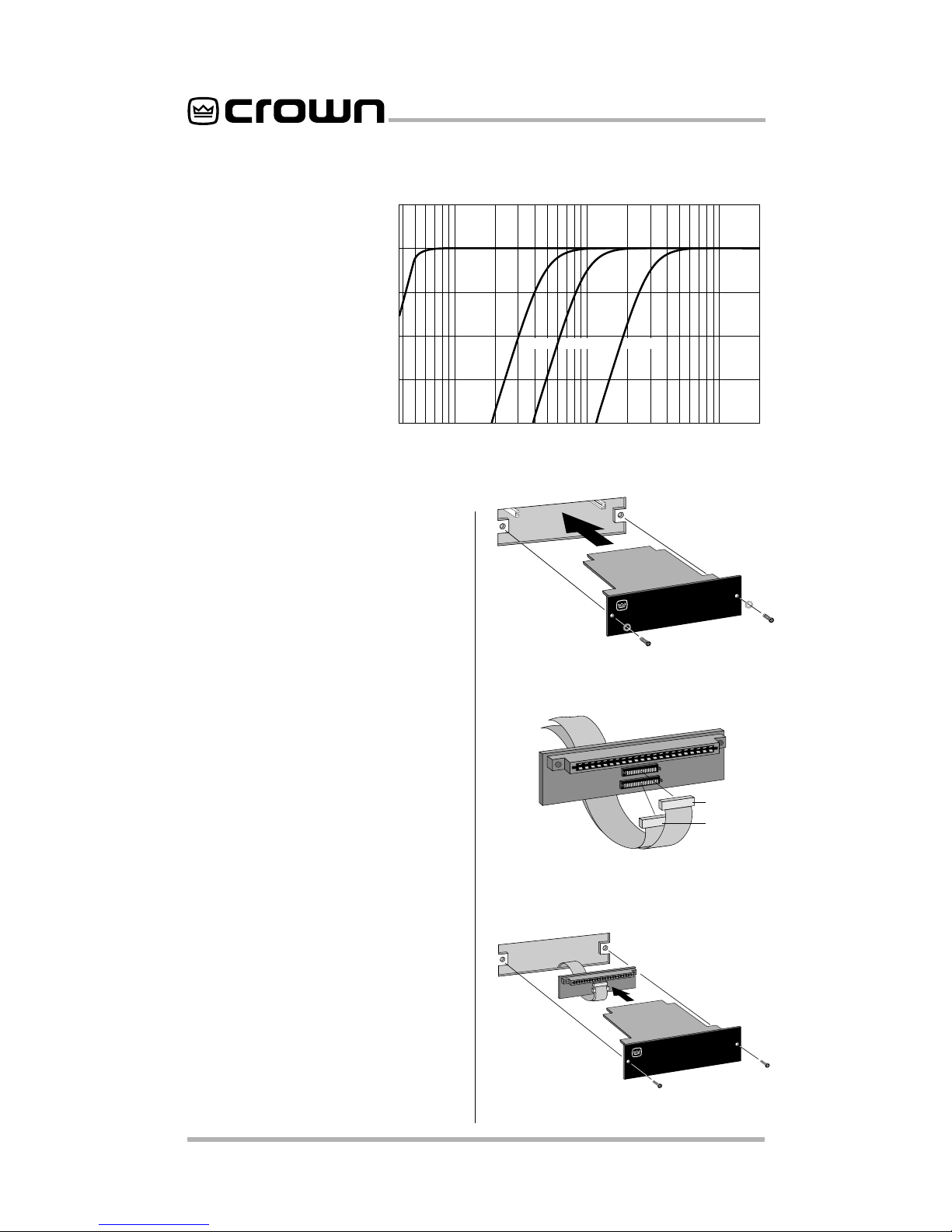
3.
StandardP.I.P.Amplifiers
:Align
the edges of the
P.I.P.–FTE
in
the
P.I.P.
card rails and firmly
pushtheunitinuntilitisseated
against the mounting bracket
(see Figure 3.3).
PIP2 Amplifiers:
(Requires a
PIP2
inputadaptor.Crownpart
number Q43528-1.) Connect
the
PIP2
input adapter to the
two input cables of the ampli-
fier(seeFigure3.4).Noticethat
the
PIP2
input adapter should
be positioned with the
P.I.P.
edgeconnectorontopandfac-
ing away from the amplifier.
The 20 pin cable (A) is con-
nectedfirstthenthe18pincable
(B) is connected. Both ribbon
cables should extend below
the
PIP2
input adapter.
Next, insert the edge connec-
tor of the
P.I.P.–FTE
into the
PIP2
inputadapter(seeFigure
3.5) and insert the assembly
into the
P.I.P.
opening in the
back of the amplifier.
4. Secure the
P.I.P.–FTE
with the
two screws and lock washers
provided. (The lock washers
are important because they
bond the
P.I.P.
to the chassis
ground of the amplifier.)
5. Connectinputandoutputwir-
ing.
6. Plug in the amplifier and turn it
on.Adjustitslevelcontrolstoa
desired setting.
Do not tamper with the circuitry.
Circuit changes made by unau-
thorized personnel, or unautho-
rized circuit modifications are not
allowed.
Remember: Crown is not liable
for any damage resulting from
overdriving other components in
your sound system.
Figure 3.6 shows how to wire a
balancedandunbalancedsource
or daisy-chain output to the bar-
rier block connectors.
Important:Iftheamplifierisused
in either Bridged-Mono or Paral-
lel-Monomode,youmustturnthe
Ch. 2 amplifier level control off
(fully counterclockwise). The in-
put and level control of Ch. 2 are
not defeated in mono mode so
any signal applied to Ch. 2 will
beat against the signal in Ch. 1.
Refer to the amplifier
Reference
Manual
formoreinformationabout
Bridged-Mono or Parallel-Mono
modes of operation.

P.I.P.–FTE
Page 8
Fig. 3.6 Audio Wiring
– + – +
BALANCED
SOURCE UNBALANCED
SOURCE
4 Specifications
SignaltoNoise:
Betterthan–85
dB (equivalent input noise) 20
Hz to 20 kHz.
CommonModeRejection:
Bet-
ter than 60 dB at 1 kHz.
Crosstalk:Crosstalk:
Crosstalk: –82 dB at 1 kHz.
InputImpedance:
Nominally20
kohm.
RecommendedSourceImped-
ance:
10 kohm or less.
Maximum Input Level:
+20 dB
at 1 kHz.
Nominal Gain:
Unity.
Frequency Response:
±1 dB
from 20 Hz to 20 kHz with filters
setflatandhorn equalization off.
High-pass (subsonic/bass) filter
has selectable –3 dB roll-off
points of 50, 100 or 300 Hz (see
Figure 4.2). Constant-directivity
horn equalization network has 3
dB rise at 3.2 kHz with 12.5 dB
peak at 24 kHz (see Figure 4.1).
Boththesefilterscanbeswitched
off if desired.
ApermanentRFIfilterwitha–3dB
roll-off at 33 kHz also affects the
response.
Dimensions:
6 3/8 x 1 7/8x 3 7/8
in. (16.2 x 4.8 x 9.8 cm).
Weight:
11ounces(312grams).
Note: All specifications refer-
enced to a 0.775 V input signal.

P.I.P.–FTE
Page 9
Notes

P.I.P.–FTE
Page 10
5 Schematic
Electronic image for this figure
were not included due to quality
considerations. Please refer to
the printed documentation.

P.I.P.–FTE
Page 11
Electronic image for this figure
were not included due to quality
considerations. Please refer to
the printed documentation.

For Technical Support contact:
Crown Audio Division Technical Support Group
Plant 2 SW, 1718 W. Mishawaka Rd., Elkhart, Indiana 46517 U.S.A.
Phone: 800-342-6939 (North America, Puerto Rico and Virgin Islands) or 219-294-8200
Fax: 219-294-8301 Fax Back (North America only): 800-294-4094 or 219-293-9200
Fax Back (International): 219-294-8100
Internet: http://www.crownaudio.com
Table of contents
Other Crown Accessories manuals

Crown
Crown Studio Reference II User manual

Crown
Crown PIP-BEQ User manual

Crown
Crown PIP-ATNB User manual

Crown
Crown PIP-ATNJ User manual

Crown
Crown PIP-RPA User manual

Crown
Crown IQ-MC4 User manual

Crown
Crown PIP-CLP User manual

Crown
Crown PIP-FMX User manual

Crown
Crown MT-BB User manual

Crown
Crown PIP-AMCB User manual
Popular Accessories manuals by other brands

IFM Electronic
IFM Electronic efector 300 SI5004 operating instructions

Kobold
Kobold MTE operating instructions

Pura
Pura VOTIVO quick start guide

Sealcom
Sealcom KAKADU Operation and installation manual

LAUMAS
LAUMAS W200 Series quick start guide

Somogyi Elektronic
Somogyi Elektronic Home TH 1000 Series instruction manual