P.I.P.-ISO
Page 3
1 Welcome
Thank you for purchasing the
Crown
P.I.P.-ISO
accessory.
P.I.P.
®modules are designed to
quickly install in the rear panel of
many Crown amplifiers.
P.I.P.
stands for “Programmable Input
Processor.” Their versatile fea-
tures expand the capabilities of
your amplifier and enable you to
customize it for your particular
needs.
The
P.I.P.-ISO
is intended for use
with ISO-MODIFIED
Com-Tech
®
series amplifiers. If it is used with
an amplifier that is not iso-modified
it will not have full isolation. In such
a case, only the input (not the out-
put) will be isolated from ground.
The
P.I.P.-ISO
comes with a “ISO-
MOD KIT” so a
Com-Tech
ampli-
fier can be iso-modified. (These
kits are also available separately.)
The amplifier modification
should be performed only by a
qualified technician. Once an
amplifier has been iso-modified, it
should not be used with any other
P.I.P.
modules except the
P.I.P.-
ISO
. (It is also possible to iso-
modify a
Macro-Tech
®series am-
plifier but the procedure is differ-
ent. Contact the Crown Technical
Support Group for more informa-
tion, if required, at 219/294-8200
or 800/342-6939.)
An iso-modified amplifier with a
P.I.P.-ISO
has completely isolated
outputs—the output voltage avail-
able between the positive and
ground terminal is not referenced
to earth ground. Even if either out-
put terminal is continuously
shorted to the earth ground (chas-
sis), no damage will occur to the
amplifier or any equipment inter-
connected to it.
The amplifier inputs are isolated
by means of input transformers.
The transformers are designed for
1 kVAC breakdown isolation and
have less than 25 pF of primary to
secondary capacitance yielding
excellent common mode rejection.
In addition to isolation, the
P.I.P.-
ISO
includes a switchable high-
pass filter to attenuate unwanted
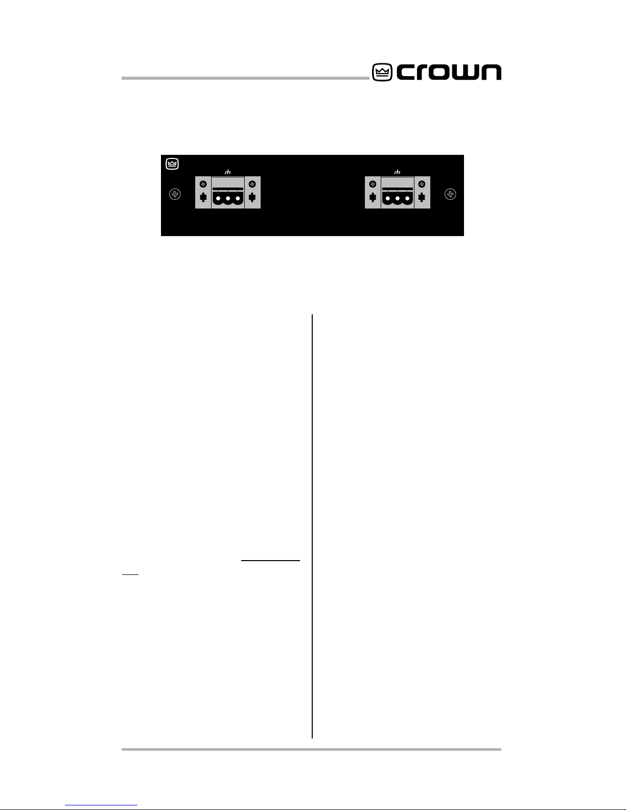
Fig. 1.1 P.I.P.-ISO
ISO
Programmable
Input Processor (P.I.P.)
—WARNING—
THIS P.I.P. PROVIDES FULL ISOLATION
FOR ISO-MODIFIED AMPLIFIERS ONLY!
DO NOT CONNECT THE OUTPUT GROUND
LUG TO THE INPUT COMMON OR CHASSIS
GROUND. REFER TO P.I.P.–ISO OWNER’S
MANUAL FOR FURTHER INFORMATION.
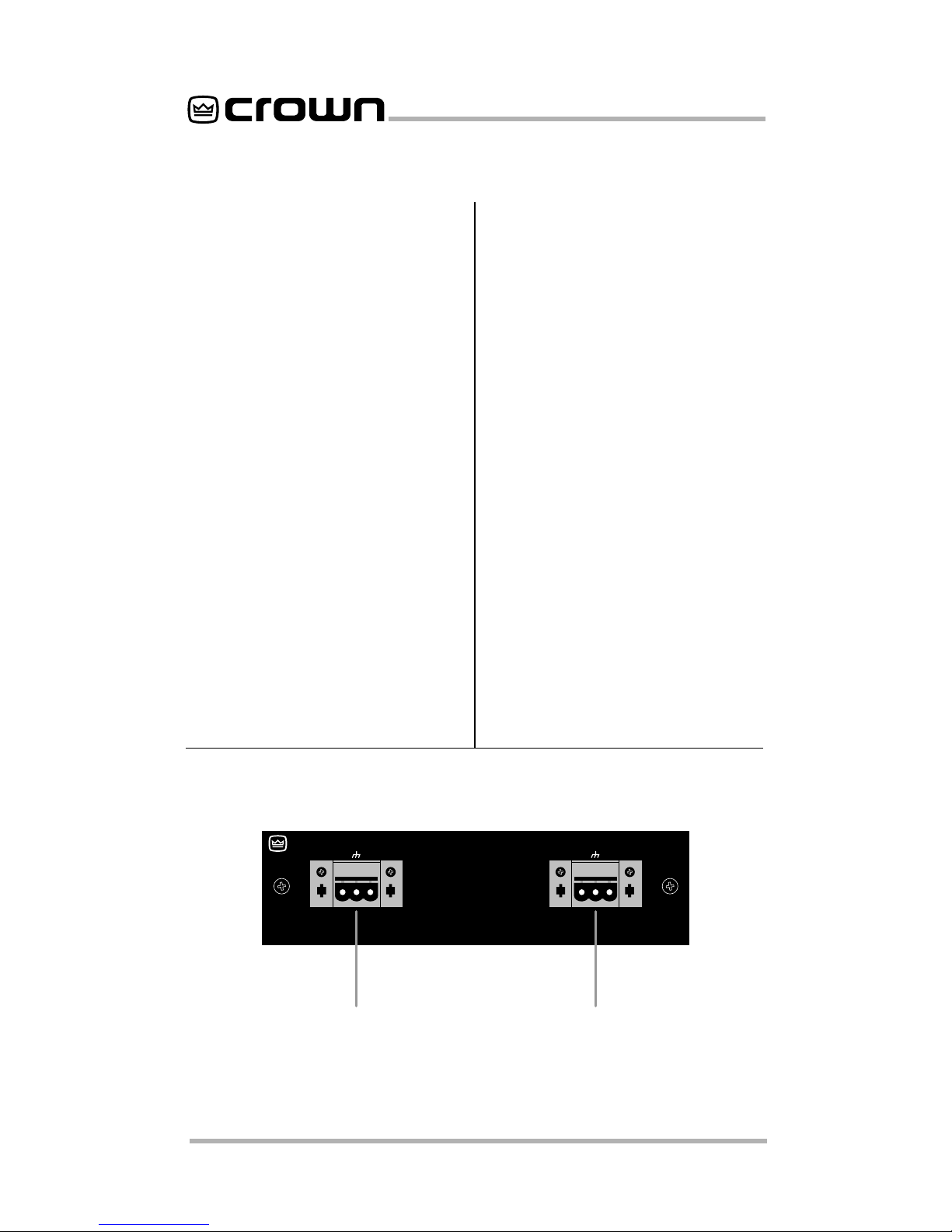
+–
CH-2 INPUT
+–
CH-1 INPUT