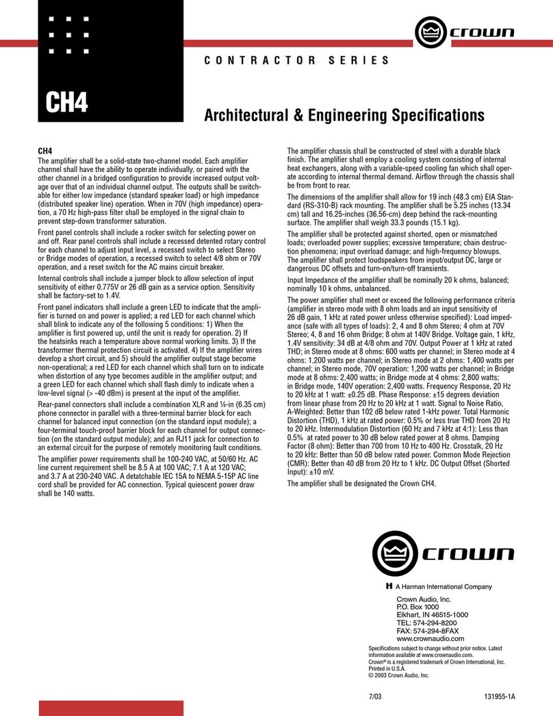
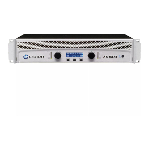
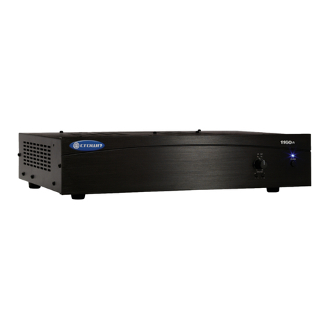
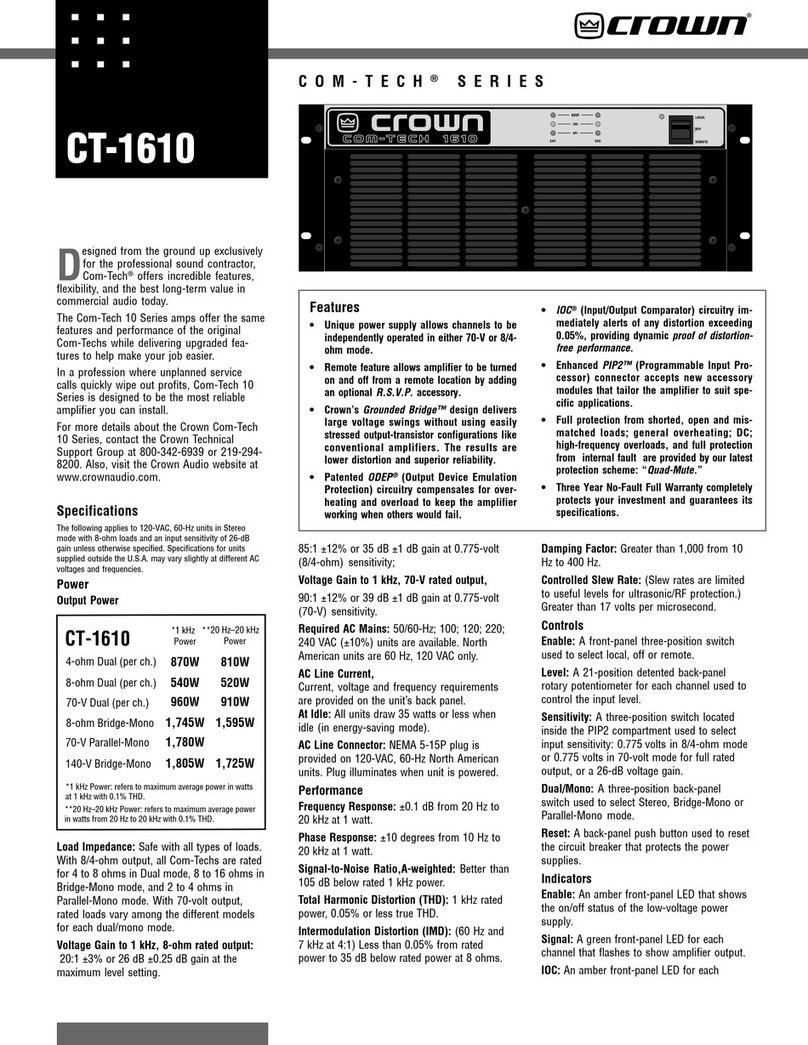
Crown Contractor Series User manual

MINARY
PRELIMINARY
MINARY
MINARY
MINA
PRELIMINA
MINARY
PRELIMINARY
PRELIMINARY
PRELIMIN
LIMINARY
LIMIN
PRELIM
PRELIM
PRELIMINARY
PRELIMIN
130808-1
5/00
Models:
CH1, CH2, CH4
CL1, CL2, CL4
Some models may be exported under the name
Amcron
.
®
ConCon
ConCon
Contrtr
trtr
tractor Seriesactor Series
actor Seriesactor Series
actor Series
Note on Preliminary Status: Crown continues to stand behind its products as guaranteed to meet or exceed
published specifications. However, at the time of this manual’s publication, not all of the CH and CL models
were in production. Guaranteed specifications for all CH and CL models will be issued at the time of product
release.
© 2000 by Crown International, Inc., P.O. Box 1000, Elkhart, IN 46515-1000 U.S.A. Telephone: 219-294-8000.
Fax: 219-294-8329. Trademark Notice:
Amcron
®
and
Crown
®are registered trademarks of Crown
International, Inc. Other trademarks are the property of their respective owners.
Obtaining Other Language Versions:
To obtain information in another language about the use of this product, please contact your local Crown Distribu-
tor. If you need assistance locating your local distributor, please contact Crown International at 219-294-8200.

Page 2
Contractor Series Power Amplifiers
Reference Manual
This page intentionally left blank

Page 3
Contractor Series Power Amplifiers
Reference Manual
Important Safety Instructions
1) Read these instructions.
2) Keep these instructions.
3) Heed all warnings.
4) Follow all instructions.
5) Do not use this apparatus near water.
6) Clean only with a dry cloth.
7) Do not block any ventilation openings. Install in ac-
cordance with the manufacturer’s instructions.
8) Do not install near any heat sources such as radia-
tors, heat registers, stoves, or other apparatus that
produce heat.
9) Do not defeat the safety purpose of the polarized or
grounding-type plug. A polarized plug has two
blades with one wider than the other. A grounding-
type plug has two blades and a third grounding
prong. The wide blade or the third prong is provided
for your safety. If the provided plug does not fit into
your outlet, consult an electrician for replacement of
the obsolete outlet.
10) Protect the power cord from being walked on or
pinched, particularly at plugs, convenience recep-
tacles, and the point where they exit from the appara-
tus.
11) Only use attachments/accessories specified by the
manufacturer.
12) Use only with a cart, stand, bracket, or table speci-
fied by the manufacturer, or sold with the apparatus.
When a cart is used, use caution when moving the
cart/apparatus combination to avoid injury from tip-
over.
13) Unplug this apparatus during lightning storms or
when unused for long periods of time.
14) Refer all servicing to qualified service personnel.
Servicing is required when the apparatus has been
damaged in any way, such as power-supply cord or
plug is damaged, liquid has been spilled or objects
have fallen into the apparatus, the apparatus has
been exposed to rain or moisture, does not operate
normally, or has been dropped.
15) To reduce the risk of fire or electric shock, do not ex-
pose this apparatus to rain or moisture.

WORLDWIDE
SUMMARY OF WARRANTY
The Crown Audio Division of Crown International, Inc., 1718 West
Mishawaka Road, Elkhart, Indiana 46517-4095 U.S.A. warrants to you, the
ORIGINAL PURCHASER and ANY SUBSEQUENT OWNER of each
NEW Crown1product, for a period of three (3) years from the date of
purchase by the original purchaser (the “warranty period”) that the new
Crown product is free of defects in materials and workmanship, and we
further warrant the new Crown product regardless of the reason for failure,
except as excluded in this Crown Warranty.
1
Note: If your unit bears the name “Amcron,” please substitute it for the
name “Crown” in this warranty.
ITEMS EXCLUDED FROM THIS CROWN WARRANTY
This Crown Warranty is in effect only for failure of a new Crown product
which occurred within the Warranty Period. It does not cover any product
which has been damaged because of any intentional misuse, accident,
negligence, or loss which is covered under any of your insurance contracts.
This Crown Warranty also does not extend to the new Crown product if the
serial number has been defaced, altered, or removed.
WHAT THE WARRANTOR WILL DO
We will remedy any defect, regardless of the reason for failure (except as
excluded), by repair, replacement, or refund. We may not elect refund
unless you agree, or unless we are unable to provide replacement, and
repair is not practical or cannot be timely made. If a refund is elected, then
you must make the defective or malfunctioning product available to us free
and clear of all liens or other encumbrances. The refund will be equal to the
actual purchase price, not including interest, insurance, closing costs, and
other finance charges less a reasonable depreciation on the product from
the date of original purchase. Warranty work can only be performed at our
authorized service centers. We will remedy the defect and ship the product
from the service center within a reasonable time after receipt of the
defective product at our authorized service center.
HOW TO OBTAIN WARRANTY SERVICE
You must notify us of your need for warranty service not later than ninety
(90) days after expiration of the warranty period. All components must be
shipped in a factory pack. Corrective action will be taken within a
reasonable time of the date of receipt of the defective product by our
authorized service center. If the repairs made by our authorized service
center are not satisfactory, notify our authorized service center
immediately.
DISCLAIMER OF CONSEQUENTIAL AND INCIDENTAL DAMAGES
YOU ARE NOT ENTITLED TO RECOVER FROM US ANY INCIDENTAL
DAMAGES RESULTING FROM ANY DEFECT IN THE NEW CROWN
PRODUCT. THIS INCLUDES ANY DAMAGE TO ANOTHER PRODUCT
OR PRODUCTS RESULTING FROM SUCH A DEFECT.
WARRANTY ALTERATIONS
No person has the authority to enlarge, amend, or modify this Crown
Warranty. This Crown Warranty is not extended by the length of time which
you are deprived of the use of the new Crown product. Repairs and
replacement parts provided under the terms of this Crown Warranty shall
carry only the unexpired portion of this Crown Warranty.
DESIGN CHANGES
We reserve the right to change the design of any product from time to time
without notice and with no obligation to make corresponding changes in
products previously manufactured.
LEGAL REMEDIES OF PURCHASER
No action to enforce this Crown Warranty shall be commenced later than
ninety (90) days after expiration of the warranty period.
THIS STATEMENT OF WARRANTY SUPERSEDES ANY OTHERS
CONTAINED IN THIS MANUAL FOR CROWN PRODUCTS.
9/90
NORTH AMERICA
SUMMARY OF WARRANTY
The Crown Audio Division of Crown International, Inc., 1718 West Mishawaka
Road, Elkhart, Indiana 46517-4095 U.S.A. warrants to you, the ORIGINAL
PURCHASER and ANY SUBSEQUENT OWNER of each NEW Crown product,
for a period of three (3) years from the date of purchase by the original purchaser
(the “warranty period”) that the new Crown product is free of defects in materials
and workmanship. We further warrant the new Crown product regardless of the
reason for failure, except as excluded in this Warranty.
ITEMS EXCLUDED FROM THIS CROWN WARRANTY
This Crown Warranty is in effect only for failure of a new Crown product which
occurred within the Warranty Period. It does not cover any product which has
been damaged because of any intentional misuse, accident, negligence, or loss
which is covered under any of your insurance contracts. This Crown Warranty
also does not extend to the new Crown product if the serial number has been
defaced, altered, or removed.
WHAT THE WARRANTOR WILL DO
We will remedy any defect, regardless of the reason for failure (except as
excluded), by repair, replacement, or refund. We may not elect refund unless you
agree, or unless we are unable to provide replacement, and repair is not practical
or cannot be timely made. If a refund is elected, then you must make the defective
or malfunctioning product available to us free and clear of all liens or other
encumbrances. The refund will be equal to the actual purchase price, not
including interest, insurance, closing costs, and other finance charges less a
reasonable depreciation on the product from the date of original purchase.
Warranty work can only be performed at our authorized service centers or at the
factory. We will remedy the defect and ship the product from the service center
or our factory within a reasonable time after receipt of the defective product at our
authorized service center or our factory. All expenses in remedying the defect,
including surface shipping costs in the United States, will be borne by us. (You
must bear the expense of shipping the product between any foreign country and
the port of entry in the United States and all taxes, duties, and other customs fees
for such foreign shipments.)
HOW TO OBTAIN WARRANTY SERVICE
You must notify us of your need for warranty service not later than ninety (90)
days after expiration of the warranty period. All components must be shipped in
a factory pack, which, if needed, may be obtained from us free of charge.
Corrective action will be taken within a reasonable time of the date of receipt of
the defective product by us or our authorized service center. If the repairs made
by us or our authorized service center are not satisfactory, notify us or our
authorized service center immediately.
DISCLAIMER OF CONSEQUENTIAL AND INCIDENTAL DAMAGES
YOU ARE NOT ENTITLED TO RECOVER FROM US ANY INCIDENTAL
DAMAGES RESULTING FROM ANY DEFECT IN THE NEW CROWN
PRODUCT. THIS INCLUDES ANY DAMAGE TO ANOTHER PRODUCT OR
PRODUCTS RESULTING FROM SUCH A DEFECT. SOME STATES DO
NOT ALLOW THE EXCLUSION OR LIMITATIONS OF INCIDENTAL OR
CONSEQUENTIAL DAMAGES, SO THE ABOVE LIMITATION OR
EXCLUSION MAY NOT APPLY TO YOU.
WARRANTY ALTERATIONS
No person has the authority to enlarge, amend, or modify this Crown Warranty.
This Crown Warranty is not extended by the length of time which you are
deprived of the use of the new Crown product. Repairs and replacement parts
provided under the terms of this Crown Warranty shall carry only the unexpired
portion of this Crown Warranty.
DESIGN CHANGES
We reserve the right to change the design of any product from time to time without
notice and with no obligation to make corresponding changes in products
previously manufactured.
LEGAL REMEDIES OF PURCHASER
THIS CROWN WARRANTY GIVES YOU SPECIFIC LEGAL RIGHTS, YOU
MAY ALSO HAVE OTHER RIGHTS WHICH VARY FROM STATE TO STATE.
No action to enforce this Crown Warranty shall be commenced later than ninety
(90) days after expiration of the warranty period.
THIS STATEMENT OF WARRANTY SUPERSEDES ANY OTHERS
CONTAINED IN THIS MANUAL FOR CROWN PRODUCTS.
9/90
Telephone: 219-294-8200. Facsimile: 219-294-8301
THREE YEAR
FULL WARRANTY
YEAR
3
YEAR
3
Printed on
recycled paper.
WATCH FOR THESE SYMBOLS:
The lightning bolt
triangle is used to
alert the user to the
risk of electric shock.
The exclamation point
triangle is used to alert the
user to important operating
or maintenance instructions.
WARNING
TO REDUCE THE RISK OF ELECTRIC
SHOCK, DO NOT EXPOSE THIS
EQUIPMENT TO RAIN OR MOISTURE!
Magnetic Field
CAUTION! Do not locate sensitive high-gain
equipment such as preamplifiers or tape decks
directly above or below the unit. Because this
amplifier has a high power density, it has a strong
magnetic field which can induce hum into unshielded
devices that are located nearby. The field is stron-
gest just above and below the unit.
If an equipment rack is used, we recommend locat-
ing the amplifier(s) in the bottom of the rack and the
preamplifier or other sensitive equipment at the top.
The information furnished in this manual does not include all of the details of design, production, or variations of the
equipment. Nor does it cover every possible situation which may arise during installation, operation or mainte-
nance. If your unit bears the name “Amcron,”please substitute it for the name “Crown”in this manual. If you need
special assistance beyond the scope of this manual, please contact our Technical Support Group.
Crown Audio Technical Support Group
Plant 2 SW, 1718 W. Mishawaka Rd., Elkhart, Indiana 46517 U.S.A.
Phone: 800-342-6939 (North America, Puerto Rico and Virgin Islands) or 219-294-8200
Fax: 219-294-8301 Fax Back (North America only): 800-294-4094 or 219-293-9200
Fax Back (International): 219-294-8100 Internet: http://www.crownaudio.com
C A U T I O N
RISK OF ELECTRIC SHOCK
DO NOT OPEN
TO PREVENT ELECTRIC SHOCK DO
NOT REMOVE TOP OR BOTTOM
COVERS. NO USER SERVICEABLE
PARTS INSIDE. REFER SERVICING TO
QUALIFIED SERVICE PERSONNEL.
DISCONNECT POWER CORD BE-
FORE REMOVING REAR INPUT
MODULE TO ACCESS GAIN SWITCH.
A V I S
RISQUE DE CHOC ÉLECTRIQUE
N’OUVREZ PAS
À PRÉVENIR LE CHOC ÉLECTRIQUE
N’ENLEVEZ PAS LES COUVERCLES. IL
N’Y A PAS DES PARTIES
SERVICEABLE À L’INTÉRIEUR. TOUS
REPARATIONS DOIT ETRE FAIRE PAR
PERSONNEL QUALIFIÉ SEULMENT.
DÉBRANCHER LA BORNE AVANT
D’OUVRIR LA MODULE EN ARRIÈRE.

Page 6
Contractor Series Power Amplifiers
Reference Manual
CONTENTS
1 Welcome ................................................................................ 9
1.1 Unpacking ............................................................................ 9
1.2 Features ................................................................................ 9
2 Controls, Indicators and Connectors ................................... 10
3 Installation ............................................................................ 12
3.1 Mounting ............................................................................. 12
3.2 Wiring .............................................................................. 12
3.2.1 Input Wiring .............................................................. 13
3.2.2 Output Wiring ........................................................... 13
4 Operation .............................................................................. 18
4.1 Precautions ......................................................................... 18
4.2 Startup Procedure ............................................................... 18
4.3 Indicators ............................................................................ 18
4.4 Controls .............................................................................. 19
5 Advanced Features and Options ......................................... 19
5.1 BCA®(CH4 and CL4 Only) .................................................. 19
5.2 Switching Power Supply with PFC (CH4 and CL4 Only) ....... 19
5.3 Crown SST Modules ............................................................ 20
5.3.1 SST-MX Crossover .................................................... 20
5.3.2 SST-SX Crossover ..................................................... 20
5.3.3 SST-SBSC Module .................................................... 21
5.4 Fault Monitoring ................................................................... 21
5.5 Constant Voltage Computer ................................................. 21
6 Principles of Operation ........................................................ 22
6.1 CH1, CH2, CL1 and CL2 ..................................................... 22
6.2 CH4 and CL4 ...................................................................... 24
6.2.1 Audio Signal Path ..................................................... 24
6.2.2 Power Supply Operation ........................................... 26
7 Specifications ....................................................................... 27
8 AC Power Draw and Thermal Dissipation ............................ 32
9 Installation Helps .................................................................. 35
9.1 Cooling .............................................................................. 35
9.1.1 Additional Cooling .................................................... 35
9.2 Input Wiring ......................................................................... 35
9.2.1 Solving Input Problems ............................................. 36
9.3 More About Output Modes .................................................. 37
9.3.1 4/8 ohm Operation (CH and CL Series) ..................... 37
9.3.2 70V and 100V Operation (CH Series Only) ................ 37
9.4. Output Wiring ..................................................................... 38
9.4.1 Solving Output Problems .......................................... 39
9.4.2 Additional Load Protection ........................................ 39
9.5 Fault Circuit Wiring .............................................................. 40
10 Applications ........................................................................ 41
10.1 Restaurant ......................................................................... 41
10.2 House of Worship .............................................................. 42
11 Service .............................................................................. 43

Page 7
Contractor Series Power Amplifiers
Reference Manual
ILLUSTRATIONS
Contractor Series ............................................................................................................ 1
This page intentionally left blank ..................................................................................... 2
Figure 1.1 Contractor Series Amplifiers ........................................................................... 8
Figure 2.1 Contractor Series Front Panel Controls and Indicators ................................. 10
Figure 2.2 CH1 & CH2 Back Panel Controls and Connectors ....................................... 10
Figure 2.3 CH4 Back Panel Controls and Connectors ................................................... 11
Figure 2.4 CL1 & CL2 Back Panel Controls and Connectors ......................................... 11
Figure 2.5 CL4 Back Panel Controls and Connectors .................................................... 11
Figure 3.1 Mounting Dimensions ................................................................................... 12
Figure 3.2 Stereo/Bridge Switch .................................................................................... 13
Figure 3.3 4/8 ohm, 70V/100V Operation Switches ........................................................ 13
Figure 3.4 CH1 & CH2 Wiring for Stereo Mode .............................................................. 14
Figure 3.5 CH1 & CH2 Wiring for Bridge Mode ............................................................. 14
Figure 3.6 CH4 Wiring for Stereo Mode ......................................................................... 15
Figure 3.7 CH4 Wiring for Bridge Mode ........................................................................ 15
Figure 3.8 CL1 & CL2 Wiring for Stereo Mode ............................................................... 16
Figure 3.9 CL1 & CL2 Wiring for Bridge Mode .............................................................. 16
Figure 3.10 CL4 Wiring for Stereo Mode ....................................................................... 17
Figure 3.11 CL4 Wiring for Bridge Mode ....................................................................... 17
Figure. 4.1 Indicators .................................................................................................... 18
Figure 5.1 SST-MX Crossover Block Diagram ................................................................ 20
Figure 5.2 SST-SX Crossover Block Diagram ................................................................. 21
Figure 5.3 SST-SBSC Crossover Block Diagram ............................................................ 21
Figure 6.1 CH1 & CH2 Circuit Block Diagram ............................................................... 22
Figure 6.2 CL1 & CL2 Circuit Block Diagram ................................................................ 23
Figure 6.3 CH4 Circuit Block Diagram ........................................................................... 24
Figure 6.4 CL4 Circuit Block Diagram ........................................................................... 25
Figure 7.1 Contractor Series Output Power ................................................................... 29
Figure 7.2 CH1 & CH2 Frequency Response ................................................................ 29
Figure 7.3 CL1 & CL2 Frequency Response ................................................................. 29
Figure 7.4 CH4 & CL4 Frequency Response ................................................................. 30
Figure 7.5 CH1, CH2, CL1 & CL2 Damping Factor ....................................................... 30
Figure 7.6 CH4 & CL4 Damping Factor ......................................................................... 30
Figure 7.7 CH1, CH2, CL1 & CL2 Output Impedance ................................................... 31
Figure 7.8 CH4 & CL4 Output Impedance .................................................................... 31
Figure 8.1 CH1 Power Draw, Current Draw and Thermal Dissipation ............................. 32
Figure 8.2 CH2 Power Draw, Current Draw and Thermal Dissipation ............................. 33
Figure 8.3 CH4 Power Draw, Current Draw and Thermal Dissipation ............................. 33
Figure 8.4 CL1 Power Draw, Current Draw and Thermal Dissipation ............................. 33
Figure 8.5 CL2 Power Draw, Current Draw and Thermal Dissipation ............................. 34
Figure 8.6 CL4 Power Draw, Current Draw and Thermal Dissipation ............................. 34
Figure 9.1 Extra Cooling with a Rack-Mounted Blower .................................................. 35
Figure 9.2 Balanced & Unbalanced Input Wiring .......................................................... 36
Figure 9.3 Polarity Conversions ..................................................................................... 36
Figure 9.4 Balanced Input Wiring ................................................................................ 36
Figure 9.5 Unbalanced Input Wiring ............................................................................ 36
Figure 9.6 Infrasonic Filter Capacitor Values ................................................................ 37
Figure 9.7 Unbalanced RFI Filters ................................................................................. 37
Figure 9.8 Balanced RFI Filters .................................................................................... 37
Figure 9.9 Wire Size Nomograph .................................................................................. 38
Figure 9.10 Inductive Load (Transformer) Network ........................................................ 39
Figure 9.11 Loudspeaker Fuse Nomograph .................................................................. 40
Figure 9.12 Fault Status LED Circuitry ........................................................................... 40
Figure 9.13 RJ Jack Wiring and Pin Assignments ......................................................... 40
Figure 10.1 Restaurant System Example ....................................................................... 41
Figure 10.2 House of Worship System Example ............................................................ 42

Page 8
Contractor Series Power Amplifiers
Reference Manual
Figure 1.1 Contractor Series Amplifiers

Page 9
Contractor Series Power Amplifiers
Reference Manual
1 Welcome
Congratulations on your purchase of a
Contractor Se-
ries
commercial power amplifier. The Contractor Series
is a complete family of amplifiers with a wide range of
power output capabilities and output configurations.
CH Series amplifiers can directly drive “constant volt-
age”lines, so you can avoid the expense of adding
step-up transformers for distributed loudspeaker sys-
tems. CL Series amplifiers offer low-impedance com-
patibility for applications where high-power,
low-impedance loads are the primary requirement.
All Contractor Series amplifiers feature Crown’s exclu-
sive
SST
(System Solutions Topologies) expansion sys-
tem. The SST expansion system makes it easy to tailor
your amplifier to a specific application or to add future
technology as it develops (see Section 5.3 for descrip-
tions of available SSTs).
Your Contractor Series amplifier is also covered by
Crown’s advance-replacement, Profit Protection Plan,
an enhancement to Crown’s exceptional Three-Year, No-
Fault, Full Warranty. Crown’s Profit Protection Plan guar-
antees quick, no-questions-asked replacement of your
covered Contractor Series amplifier should it fail at any
time during the original 3-year warranty period follow-
ing the date of original purchase.
This manual will help you successfully install and use
your new Contractor Series amplifier. Please read all
instructions, warnings and cautions. Be sure to read
Section 3.2 if you plan to use the amplifier in Bridge
mode, or if you plan to drive “constant voltage”lines.
Also, for your protection, please send in your warranty
registration card today, and save your bill of sale as it is
your official proof of purchase.
1.2 Features
The Contractor Series amplifiers are designed specially
for fixed installation, and include the following features:
❏CH Series provides for both low impedance and high
impedance loads, with the choice of 4/8 ohm or 70V
operation for each channel (CH1 and CH2 also offer
100V operation). The output mode of each channel can
be set independently, allowing unique or mismatched
loads to be driven by each channel.
❏CH Series includes a 70-Hz high-pass filter for each
channel (when used in 70V or 100V mode) providing
necessary low-frequency roll-off to eliminate saturation of
constant voltage step-down transformers typically used
in 70V and 100V distributed systems.
❏CL Series includes high power 2-ohm operation, for jobs
where low impedence is the only requirement.
❏A green Signal LED for each channel flashes when a
signal is present at the input.
❏A red Clip LED for each channel turns on when distortion
becomes audible in the amplifier output.
❏A red five-way Fault LED for each channel blinks during
amplifier power-up, and upon the following fault
conditons: excessive heatsink temperature; transformer
thermal protection; short at amplifier output; output stage
non-operational.
❏An RJ11 connector allows external circuits to monitor the
status of the Fault circuit.
❏Precision detented level controls are located on the back
panel for security, and allow for accurate level settings.
❏Barrier strip output connectors allow for quick easy con-
nection regardless of the load, and accept up to 10 AWG
crimp-on terminal forks.
❏SST modules provide flexible input options, such as
onboard crossover configurations.
❏Stereo/Bridge switch allows conversion from Stereo
mode to Bridge mode for higher-powered single-channel
operation.
❏Advanced protection circuitry guards against: shorted
outputs, open circuits, DC, mismatched loads, general
overheating, high frequency overloads and internal
faults.
❏Mounts in standard 19-inch (48.3-cm) equipment racks.
❏Three year, “No-Fault,”Full warranty completely protects
your investment and guarantees its specifications.
❏Crown’s advance-replacement Profit Protection Plan pro-
vides quick, no-questions-asked replacement of cov-
ered amps.
1.1 Unpacking
Please unpack and inspect your new amplifier for any
damage that may have occurred during transit. If dam-
age is found, notify the transportation company imme-
diately. Only you, the consignee, may initiate a claim for
shipping damage. Crown will be happy to cooperate
fully, as needed. Save the shipping carton as evidence
of damage for the shipper’s inspection.
Even if the unit arrived in perfect condition, (as most
do), save all packing materials, so you will have them if
you ever need to transport the unit. NEVER SHIP THE
UNIT WITHOUT THE FACTORY PACK.

Page 10
Contractor Series Power Amplifiers
Reference Manual
Figure 2.1 Contractor Series Front Panel Controls and Indicators
2 Controls, Indicators and
Connectors
Figure 2.2 CH1 & CH2 Back Panel Controls and Connectors

Page 11
Contractor Series Power Amplifiers
Reference Manual
Figure 2.3 CH4 Back Panel Controls and Connectors
Figure 2.4 CL1 & CL2 Back Panel Controls and Connectors
Figure 2.5 CL4 Back Panel Controls and Connectors

Page 12
Contractor Series Power Amplifiers
Reference Manual
3 Installation
This section covers basic Contractor Series installation
procedures. All Contractor Series
amplifiers are in-
tended for rack mount installations using a commer-
cial 19-inch (48.3-cm) EIA rack standard metal
cabinet wired with a commercial grade electrical
outlet box and receptacles. Contractor Series ampli-
fiers utilize a 3-foot (1-meter) power cord for such
installations. Do NOT use extension cords.
Begin with the amplifier turned off and disconnected
from the power receptacle. The Contractor Series
power switch is located on the left side of the front panel;
it is OFF when depressed on the left. Equipment that
will be connected to the inputs of the amplifier (such as
mixers,equalizers or signal processors) should also be
turned off.
3.1 Mounting
Contractor Series amplifiers are designed for standard
19-inch (48.3-cm) equipment rack mounting, or stack-
ing without a cabinet. In a rack, it is best to mount units
directly on top of each other. This provides the most
efficient air flow and support. If the amplifier(s) will be
mounted in an enclosed rack, assure there is adequate
ventilation (see Section 9.1 for more information on cool-
Figure 3.1 Mounting Dimensions
ing). If the rack will be transported, we recommend that
you fasten the amplifier’s back panel securely to the
rack to help support the unit’s weight.
As you can see in Figure 3.1, Contractor Series amplifi-
ers vary in their depth demensions. Figure 3.1 shows
the physical demensions of all models. The depths for
Contractor Series models are also listed here:
CH1, CH2, CL1 and CL2 Depth: 12.5 inches
(31.11 cm)
CH4 and CL4 Depth: 16.25 inches (36.56 cm)
3.2 Wiring
Proper wiring depends on how you configure your am-
plifier. First, the Output Mode for each output channel
can be independently configured to drive step-down
transformers in a distributed “constant voltage”loud-
speaker system (70V/100V operation with CH1 and
CH2 only, or 70V operation with CH4 only) or loudspeak-
ers that do not have step-down transformers (4/8 ohm
mode). Second, the amplifier can be configured for Dual
or Bridge modes. Various combinations of these modes
are possible, so be sure to note any special wiring re-
quirements for the mode you will be using.

Page 13
Contractor Series Power Amplifiers
Reference Manual
Contractor Series
amplifiers can be configured for ei-
ther Stereo (dual channel) or Bridge (single mono chan-
nel) modes of operation. To switch your amplifier
accordingly, set the recessed “Stereo/Bridge”switch to
the desired setting as shown in Figure 3.2. For Stereo
operation, slide the swtch to the left, and for Bridge op-
eration, slide the switch to the right.
Figure 3.2 Stereo/Bridge Switch
CH Series amplifiers only: select 4/8 ohm, 70V or 100V
operation as appropriate for your application and your
amplifier. CH1 and CH2 amplifiers allow 4/8 ohm, 70V
or 100V operation, and CH4 amplifiers allow 4/8 ohm
and 70V operation. Select output operation by sliding
the recessed Output Operation switches to the desired
position as shown in Figure 3.3. For 4/8 ohm operation,
slide the switch all the way to the left, for 70V or 100V
operation, slide the switch all the way to the right.
lected, the 70V and 100V connections are inactive, with
no audio present at those Output Terminals.
Figures 3.4 through 3.11 on the following pages show
common ways to install Contractor Series amplifiers in
a sound system. Input and output terminals are located
on the back panel. Please use care when making con-
nections, selecting signal sources and controlling the
output level. The load you save may be your own!
Crown assumes no liability for damaged loads result-
ing from careless amplifier use or deliberate overpow-
ering.
CAUTION: Always disconnect the AC power and
turn the level controls off when making or breaking
connections. This is very important when loudspeak-
ers are connected because it reduces the chance of
loud blasts that can cause loudspeaker damage.
CAUTION: Never tie an amplifier’s outputs together
directly while in Stereo mode. Never parallel them
with the output of another amplifier. Such connec-
tions do not result in increased output power, but may
cause overheating and premature activation of the pro-
tection circuitry.
Note: The Channel 2 input jack and Input Level control
are not defeated in Bridge mode. A signal feeding
Channel 2 will work against the Channel 1 signal, and
usually results in distortion and inefficient operation.
3.2.1 Input Wiring
The balanced inputs have a nominal impedance of 20 k
ohms (10 k ohms unbalanced) and will accept the line-
level output of most devices. The factory installed SST
module provides a balanced three-terminal barrier
block and a Neutrik®Combo XLR/phone connector for
each input. Various SSTs are also available which pro-
vide a range of input signal processing features (See
Section 5.3).
You can choose to use either balanced or unbalanced
wiring. Balanced wiring offers the most rejection of in-
terference, and is typically preferred, especially for long
cable runs. See Section 9.2 for more information about
balanced and unbalanced input wiring.
3.2.2 Output Wiring
Consider the power handling capacity of your load be-
fore connecting it to the amplifier. Fusing loudspeaker
lines is highly recommended (see Section 9.4.2).
Contractor Series amplifier output connectors accept
up to 10 AWG crimp-on terminal forks. Use high-quality
cable, with sufficient gauge for your application. See
Section 9.4 for tips on choosing speaker cable.
Figure 3.3 4/8 ohm, 70V/100V Operation Switches
When the CH Series amplifier is set up for two-channel
(Stereo mode) operation, it is possible to configure the
output channels for any combination of 4/8 ohm, 70V or
100V operation.
WARNING: If Bridge mode is used with 70V output,
the amplifier will actually deliver 140 volts, or if used
with 100V output, the amplifier will actually deliver
200 volts.
WARNING: The two Output Operation switches must
be set to identical positions (4/8 ohm or 70V/100V
mode) when operating in Bridge mode. Never
change switch positions with power turned on.
CAUTION: Output Terminals are activated by selec-
tion of an output operation mode via the Output Op-
eration switches. All other Output Terminals are
inactive. For example, when 4/8 Ohm Operation is se-
CH1 and CH2 Models
CH4 Model

Page 14
Contractor Series Power Amplifiers
Reference Manual
Figure 3.4 CH1 & CH2 Wiring for Stereo Mode
Figure 3.5 CH1 & CH2 Wiring for 140V Bridge Mode

Page 15
Contractor Series Power Amplifiers
Reference Manual
Figure 3.6 CH4 Wiring for Stereo Mode
Figure 3.7 CH4 Wiring for Bridge Mode

Page 16
Contractor Series Power Amplifiers
Reference Manual
Figure 3.8 CL1 & CL2 Wiring for Stereo Mode
Figure 3.9 CL1 & CL2 Wiring for Bridge Mode

Page 17
Contractor Series Power Amplifiers
Reference Manual
Figure 3.10 CL4 Wiring for Stereo Mode
Figure 3.11 CL4 Wiring for Bridge Mode

Page 18
Contractor Series Power Amplifiers
Reference Manual
4 Operation
4.1 Precautions
Contractor Series amplifiers are protected from internal
and external faults, but you should still take the follow-
ing precautions for optimum performance and safety:
1. Improper wiring for the Stereo or Bridge-Mono modes,
as well as the 4/8 Ohm, 70V and 100V output modes
can result in serious operating difficulties. Refer to Sec-
tion 9.4 for details.
2. WARNING: Never operate the amplifier in Bridge
mode unless both Output Operation switches are
configured identically (4/8 Ohm, 70V or 100V).
3. WARNING: Do not change the position of the Stereo/
Bridge switch or the Output Operation switches un-
less the amplifier is first turned off.
4. Use care when making connections, selecting signal
sources and controlling the output level. The load you
save may be your own!
5. Do not connect input and output ground leads together.
Ground loops and oscillations may result.
6. Never connect the output to a power supply output,
battery or power main. Electrical shock may result.
7. Tampering with the circuitry by unqualified personnel, or
making unauthorized circuit changes may be hazard-
ous and invalidates all agency listings.
Remember: Crown is not liable for damage that results
from overdriving other system components.
4.2 Startup Procedure
Use the following procedure when first turning on your
amplifier:
1. Turn down the level of your audio source.
2. Turn down the level controls of the amplifier.
3. Turn on the Enable switch. The Enable indicator
should glow. During power-up, the Fault indica-
tors will flash as described in Section 4.3. After
power-up, the Fault indicators will turn off and all
other indicators should function normally.
4. After the turn-on delay, turn up the level of your
audio source to the desired level.
5. Turn up the Input Level controls on the back panel
of the amplifier until the desired loudness or
power level is achieved.
6. Turn down the level of your audio source to its
normal range.
If you ever need to make any wiring or installation
changes, don’t forget to disconnect the power cord.
4.3 Indicators
The front panel of a Contractor Series amplifier has sev-
eral helpful indicators (Figure 4.1). The blue Power in-
dicator shows that the amplifier has been turned on
and has power.
Figure 4.1 Indicators
The red Fault indicators blink under five different con-
ditions:
1. When the amplifier is first powered up, until the
unit is ready for operation.
2. If the heatsinks reach a temperature above nor-
mal working limits. This can be caused by any
number of abnormal conditions including but not
limited to extremely low load impedance and/or
inadequate cooling (see Section 9.1 for more in-
formation on cooling).
3. If the transformer (high-voltage power supply)
thermal protection circuit is activated. Higher
than rated output levels, excessively low-imped-
ance loads and unreasonably high input signals
can generate more heat in the power supply
than in the output devices. This can overheat the
power supply and activate the Fault protection
circuit.
4. If amplifier output wires develop a short-circuit.
This could be caused by a short anywhere along
the circuit from the output connectors to the
speakers, including shorted speaker drivers.
5. Should the amplifier output stage become non-
operational.
The red Clip indicators turn on when distortion is au-
dible in the amplifier output.
Unlike other Crown amplifiers, the green Signal Pres-
ence Indicators (SPI) on Contractor Series amplifiers
illuminate when a signal (>–40 dBm) is present at the
INPUT of the amplifier. This indicator is before the level
control, so it can be used to troubleshoot wiring prob-
lems within a system. If the indicators are not lit, signal
is not reaching the amplifier.

Page 19
Contractor Series Power Amplifiers
Reference Manual
4.4 Controls
The Enable switch is located on the front panel so you
can easily turn the amplifier on and off.
A 21-position Precision Detented Level Control is pro-
vided for each channel. Level attenuation may be ad-
justed in precise steps. For security, the level controls
are located on the back panel. Input Sensitivity is fac-
tory set for 1.4V for each channel. With this setting, a
1.4V input signal will drive the amplifier to full power into
an 8-ohm load when the Level Controls are turned to
maximum. This setting works best when the amplifier is
being driven by equipment with a +4 dBu output. Op-
tionally, the Input Sensitivity for each channel may be
individually set to either 0.775V or 26 dB. To have the
input sensitivity changed on your amplifier, contact a
Crown authorized servicer (see Section 11) .
A two-position Mode switch, located on the back panel,
allows the selection of either Stereo or Bridge mode of
operation.
Stereo mode provides identical power output to each of
the two amplifier output channels. Bridge mode com-
bines the two amplifier output channels into a single
mono channel with twice the voltage of a single stereo
channel. It does this by bridging the outputs, and it re-
quires special output wiring. Do NOT select Bridge
mode without first making sure the amplifier has
been wired in a Bridge-Mono configuration. For more
information on wiring for Bridge mode, see the Installa-
tion section of this manual (Section 3)
,
or consult your
system installer.
When Bridge mode is selected, only the Channel 1
Level control and the Channel 1 Signal indicator will
work. If the Channel 2 input is wired, the Channel 2 Level
Control should be turned all the way down (counter/anti-
clockwise) to prevent distortion.
A two-position Output Operation switch (CH Series
amplifiers only) allows the selection of either 4/8 ohm,
70V or 100V output from the amplifier. See Section 9 for
more information about output operating modes.
Fault Jack: This RJ11 jack (which looks like a phone
jack) is located on the back panel. By attaching a signal-
ling device to the Fault jack, you can monitor the amplifier’s
Fault status from a remote location. See the Advanced
Features and Options section (Section 5) of this manual
for more information on fault monitoring and suggestions
for signalling device circuity.
A circuit breaker is provided to prevent the high-voltage
power supplies from drawing excessive current. A Re-
set switch for the circuit breaker is provided on the back
panel. If the circuit breaker trips, the Power indicator
turns off. In this situation, turn off the Power switch and
reset the circuit breaker. Then, turn the Power switch
back on. If it trips again or the unit fails to operate prop-
erly, contact an authorized service center or Crown’s
Technical Support Group.
5 Advanced Features and
Options
5.1
BCA
® (CH4 and CL4 Only)
BCA (Balanced Current Amplifier) is Crown’s patented,
cutting-edge technology that gets more power out of an
amplifier with less waste than was ever before possible.
A completely new adaptation of standard amplifier de-
sign, Crown’s BCA “switching”amplifier design pro-
vides for high output, exceptional reliability and nearly
twice the efficiency of typical amplifier designs.
While switching designs have been used successfully
in other applications, these designs were never before
suitable for use in precision, high-power audio amplifier
applications. Crown’s BCA technology changes that,
with a totally new paradigm for amplifier design that rep-
resents the future of professional amplifiers.
With their superior efficiency, BCA amplifiers can help
to keep power requirements lower, while still providing
excellent audio reproduction. And Crown BCA amplifi-
ers are tough—easily handling very low (and highly re-
active) load impedances, even under extreme
conditions. In fact, Crown BCA amps have far out-per-
formed competitive amplifiers in tests where the ampli-
fier was run as much as 12-dB into clip for extended
periods of time.
5.2 Switching Power Supply with PFC (CH4 and
CL4 Only)
Crown’s new Switching Power Supply with PFC pro-
vides a range of benefits over both non-switching and
conventional switching power-supply designs.
Typical non-switching power supplies require large
transformers in order to produce the required power at
the output stage. These transformers must be large to
absorb the waste that occurs when operating at 50 to
60 Hz (standard AC supplied by the power company).
By contrast, switching power supplies can operate with
a much smaller (and lighter) transformer because they
first convert the AC up to a much higher frequency,
thereby reducing waste.

Page 20
Contractor Series Power Amplifiers
Reference Manual
However, in both non-switching and conventional
switching designs, phase differences occur within the
power supply due to the inductance of the transformer.
This phase difference prevents much of the available
power from the AC mains from making its way to the
load.
PFC, however, compensates for phase differences in
the power supply, allowing more true power to be trans-
ferred to the amplifier. The result is more power with less
waste than any other conventional switching or non-
switching design.
As an added benefit, PFC also allows the amp to be
connected to any common AC line voltage, without con-
verting the power supply. This means that the CH4 and
CL4 are ready for any common line voltage.
5.3 Crown SST Modules
Crown optional SST (System Solution Topologies) mod-
ules were specially designed to improve the fidelity and
versatility of your audio system. They feature a variety
of professional signal routing and filtering capabilities,
with active crossovers that allow the audio signal to be
split and sent to auxiliary amplifiers. Your choice of SST
modules can be easily added to the amplifier by any
authorized Crown Service Center.
For information on wiring and configuration of amplifi-
ers equipped with an optional Crown SST crossover
module, please refer to the applicable SST Crossover
Reference Manual.
Refer to the following descriptions for an overview of
available Crown SST crossover modules.
5.3.1 SST-MX Crossover
The SST-MX crossover module features 24-dB/octave
Linkwitz-Riley tuned filters and stereo sub-bass outputs
for biamp operation of subs. See Figure 5.1 for SST-MX
block diagram.
Features of the SST-MX crossover include:
•Stereo biamp.
•100-Hz fixed crossover
•24-dB/octave Linkwitz-Riley tuned filters.
•Neutrik®Combo ¼-inch (6.35-mm) and XLR in-
put jacks.
•Barrier block balanced outputs.
•Optional high-pass filter bypass on amplified
outputs adapts system for full-range use.
5.3.2 SST-SX Crossover
The SST-SX crossover module features 24-dB/octave
Linkwitz-Riley tuned filters and mono-summed sub-
bass outputs for biamp operation of subs. See Figure
5.2 for SST-SX block diagram.
Features of the SST-SX crossover include:
•Mono-summed sub-bass output.
•24-dB/octave Linkwitz-Riley tuned filters.
•Crossover switchable between 80 and 120 Hz.
•Neutrik®Combo (6.35-mm and XLR) input jacks.
•Male 3-pin XLR outputs
•Optional high-pass filter bypass on amplified
output adapts system for full-range use.
CH1
CH1 SUB OUT
TB
CH2 SUB OUT
100 Hz LP
CH2
–
–
+
+
IN
BYPASS
100 Hz HP
HOST
AMPLIFIER
CH1 INPUT
HOST
AMPLIFIER
CH2 INPUT
100 Hz LP
24 dB/oct. slope
100 Hz HP
24 dB/oct. slope
IN
BYPASS
100 Hz LP
24 dB/oct. slope
100 Hz HP
24 dB/oct. slope
–
+
–
+
–
+
3
2
1
–
+
3
2
1
Figure 5.1 SST-MX Crossover Block Diagram
This manual suits for next models
5
Table of contents
Other Crown Amplifier manuals

Crown
Crown CDi 2000 User manual

Crown
Crown CP660 User manual

Crown
Crown Macro-Tech 5002 VZ User manual

Crown
Crown XS1200 User manual

Crown
Crown 2650 User manual

Crown
Crown XTi 4000 User manual

Crown
Crown Pulse 21100 User manual

Crown
Crown PowerTech PT 3.1 User manual

Crown
Crown 140MPA User manual

Crown
Crown I-Tech HD Series User manual

Crown
Crown XTi 6002 User manual

Crown
Crown Macro-Tech MA-602 User manual

Crown
Crown CTs 1200 Parts list manual

Crown
Crown CDi 6000 User manual

Crown
Crown DC-300A II Quick start guide

Crown
Crown CP660 User manual

Crown
Crown PSA-2 Manual

Crown
Crown CTs 1200 Manual

Crown
Crown PL-2 User manual

Crown
Crown CTs 1200 User manual