INSTALLATION AND OPERATION MANUAL,
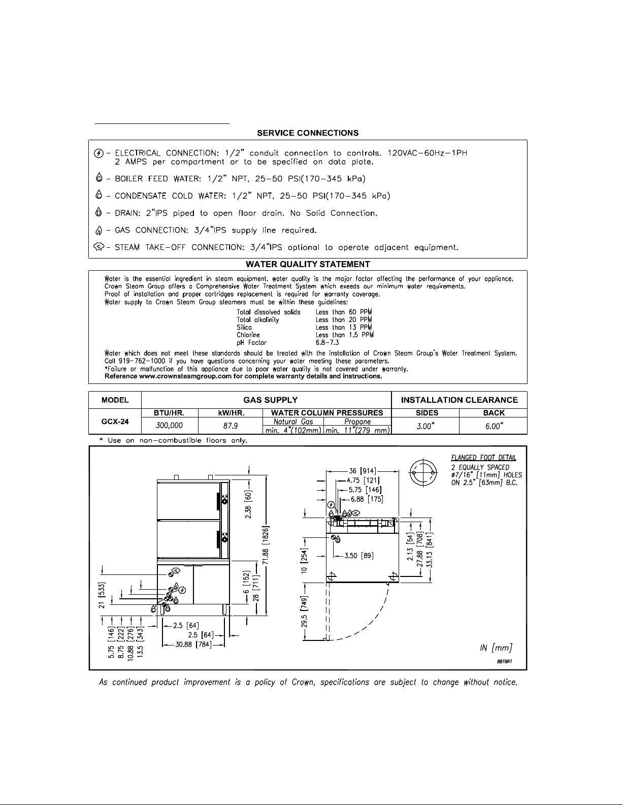
GAS CABINET BASE CONVECTION STEAMER, GCX-16, GCX-24
3.0 INSTALLATION INSTRUCTIONS (Continued)
INSTALLATION CODES AND STANDARDS
The appliance must be installed in accordance with:
Gas installation to conform to local codes, or in absence of local codes, with the National Fuel
Gas Code - ANSI Z223.1/NFPA 54, or the Natural Gas and Propane Installation Code, CSA
B149.1, as applicable, including:
1. The appliance and its individual shut off valve must be disconnected from the gas supply
piping system during any pressure testing of that system at pressures in excess of ½ psig
(3.5 kPa).
2. The appliance must be isolated from the gas supply piping system by closing its individual
manual shut off valve during any pressure testing of the gas supply piping system at test
pressures equal to or less than ½ psig (3.5 kPa).
Electrical grounding must be provided in accordance with local codes, or in the absence of local
codes, with the National Electrical Code ANSI/NFPA 70. In Canada, installation must be in
accordance with the Canadian Electrical Code CSA C22.2.
WIRING DIAGRAM FOR APPLIANCE IS LOCATED INSIDE CABINET DOOR.
LEVELLING AND ANCHORING THE APPLIANCE
1. Place appliance in the installation position.
2. Place a carpenter’s level on top of the appliance and turn the adjustable feet to level side-
to-side and front-to-back.
3. Mark hole locations on the floor through the anchoring holes provided in the rear flanged
adjustable feet.
4. Remove appliance from installation position and drill holes in locations marked on the floor.
Insert proper anchoring devices (not supplied).
5. Place appliance back in the installation position.
6. Place carpenter’s level on top of appliance and re-level side-to-side and front-to-back.
7. Bolt and anchor appliance securely to the floor.
8. Seal bolts and flanged feet with Silastic or equivalent compound.
MANUAL 10064R2 8 2020-07-13