Crown EMT-6 User manual

MANUAL 10071 REV 4 (07/22)
$21.00
Direct Steam Kettles Mounted on
Electric Boiler Cabinet Base
MANUAL SECTION CO
IMPORTANT FOR FUTURE REFERENCE
Please complete this information and retain this
manual for the life of the equipment:
Model #:
___________________________
Serial #:
___________________________
Date Purchased:
_____________________
WARNING
Improper installation, adjustment, alteration, service or maintenance can cause property damage, injury
or death. Read the installation, operating and maintenance instructions thoroughly before installing or
servicing this equipment.
Installation & Operation Manual
Model EMT-10-10
CROWN FOOD SERVICE EQUIPMENT
A Middleby Company
70 Oakdale Road, Downsview (Toronto) Ontario, Canada, M3N 1V9
Telephone: 919-762-1000 www.crownsteamgroup.com
Direct Steam Kettles
Mounted on Electric Boiler Cabinet Base
EMT-6, EMT-10, EMT-12,
EMT-6-6, EMT-10-6 & EMT-10-10

PAGE 2 OF 20 INSTALLATION & OPERATION MANUAL 10071 REV 4 (07/22)
SAFETY PRECAUTIONS
precautions. Accidents and problems can be caused by failure to follow fundamental rules and precautions.
The following symbols, found throughout this manual, alert you to potentially dangerous conditions to the operator,
service personnel, or to the equipment.
CAUTION
WARNING
NOTICE
This symbol warns of immediate hazards that will result in severe injury or death.
This symbol refers to a potential hazard or unsafe practice that could result in injury or death.
This symbol refers to a potential hazard or unsafe practice that could result in injury, product
damage, or property damage.
This symbol refers to information that needs special attention or must be fully
understood, even though not dangerous.
DANGER
WARNING
Improper installation, operation, adjustment, alteration, service or maintenance can cause property damage, injury
or death. Read the installation, operating and maintenance instructions thoroughly before installing, operating or
servicing this equipment.
NOTICE
This manual should be retained for future reference.
NOTICE
IMPORTANT NOTES FOR INSTALLATION AND OPERATION
WARNING
This is the safety alert symbol. It is used to alert you to potential personal injury hazards. Obey all safety messages
that follow this symbol to avoid possible injury or death.
WARNING
WARNING
Disconnect the power supply to the appliance before cleaning or servicing.
CAUTION

PAGE 3 OF 20
INSTALLATION & OPERATION MANUAL 10071 REV 4 (07/22)
Table of Contents
Important Notes For Installation and Operation.................................................................... 2
............................................................................................................. 4
Introduction ........................................................................................................................... 8
Installation Instructions ......................................................................................................... 9
Operation .............................................................................................................................. 11
................................................... 12
Periodic Maintenance ........................................................................................................... 13
Cleaning................................................................................................................................ 14
Adjustments .......................................................................................................................... 15
Troubleshooting .................................................................................................................... 17
TC

PAGE 4 OF 20 INSTALLATION & OPERATION MANUAL 10071 REV 4 (07/22)
SERVICE CONNECTIONS
DISCLAIMER
WATER QUALITY STATEMENT
............................
Total alkalinity ........................................ .........................6.8 - 7.3
.......................................................
concerning your water meeting these parameters.
*Failure or malfunction of this appliance due to poor water quality is not covered under warranty.
Reference www.crownsteamgroup.com for complete warranty details and instructions.
ELECTRICAL CHARACTERISTICS
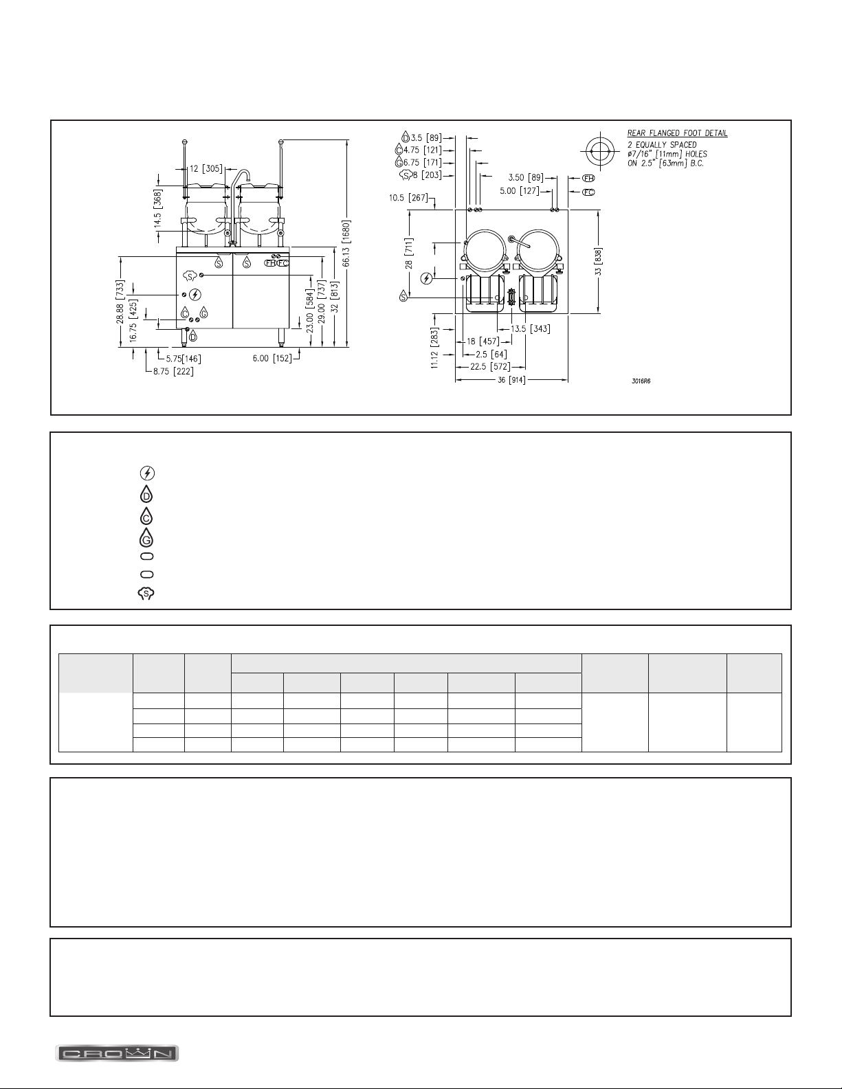
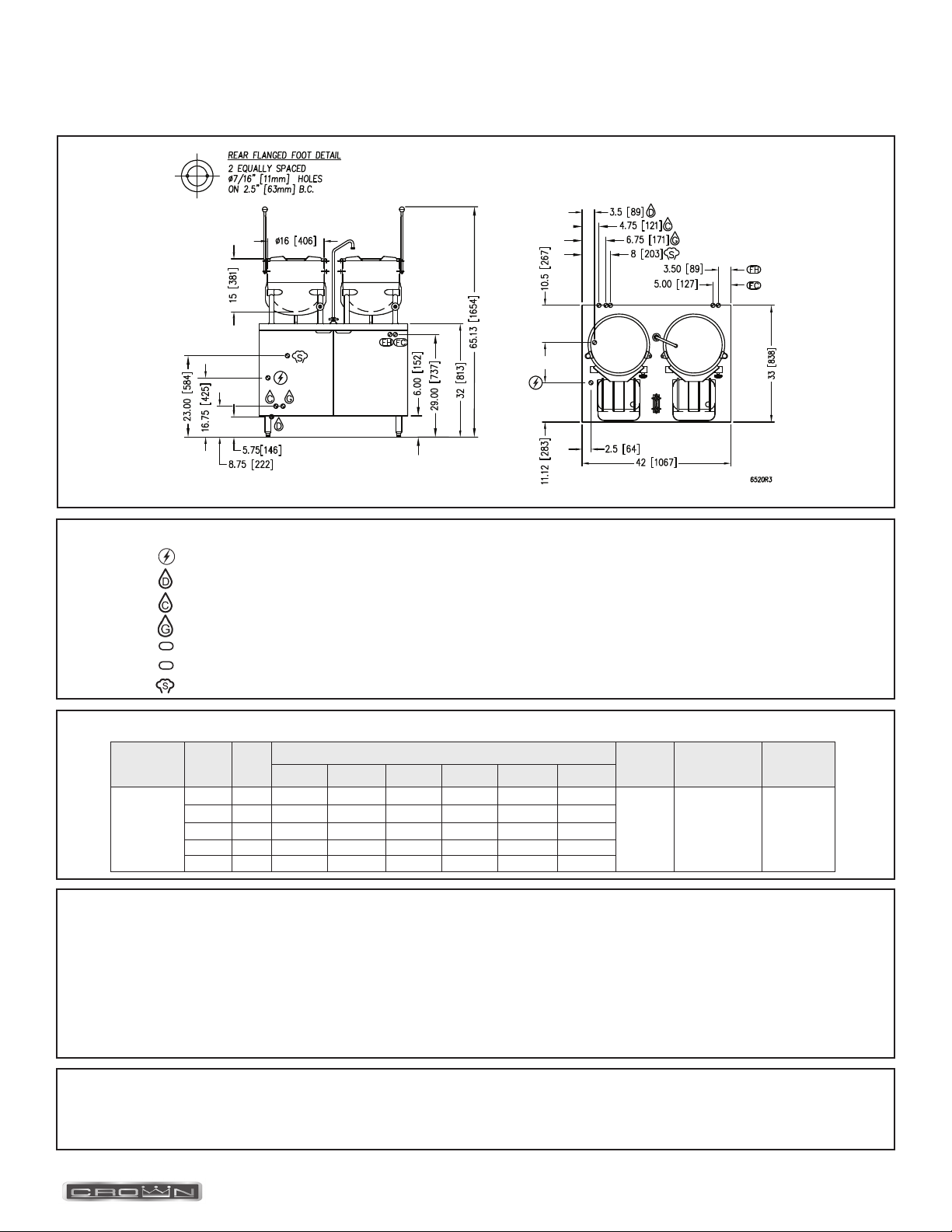
DIMENSIONS AND SPECIFICATIONS
FC
FH
EMT-6 12 (305) 14.5 (368) 66.13 (1680)
3.5
(89)
10.5
(267)
8.75
(222)
5.5
(140)
7
(178)
2.5
(64)
11.12
(283)
9
(229)
12
(305)
450 lbs. [204 kg.]
EMT-10 16 (406) 15 (381) 65.13 (1654) 470 lbs. [213 kg.]
EMT-12 16 (406) 17 (432) 67.13 (1705) 479 lbs. [217 kg.]
208V 220V 240V 380V 415V 480V
EMT-6
EMT-10
EMT-12
3 24 66.6 63 57.7 36.5 33.4 28.9
3 36 99.9 94.5 86.6 54.7 50.1 43.3
3 42 116.6 110.2 101 63.8 58.4 50.5
3 48 115.5 72.9 66.8 57.7
Terry System Cartridge Changes / Installation
water supply being fed to the steamer. Failure to do so can result in component damage within the steamer which is not covered under warranty.

PAGE 5 OF 20
INSTALLATION & OPERATION MANUAL 10071 REV 4 (07/22)
SERVICE CONNECTIONS
DISCLAIMER
WATER QUALITY STATEMENT
............................
Total alkalinity ........................................ .........................6.8 - 7.3
.......................................................
concerning your water meeting these parameters.
*Failure or malfunction of this appliance due to poor water quality is not covered under warranty.
Reference www.crownsteamgroup.com for complete warranty details and instructions.
IN [MM]
ELECTRICAL CHARACTERISTICS AND SPECIFICATIONS
208V 220V 240V 380V 415V 480V
EMT-6-6
3 24 66.6 63 57.7 36.5 33.4 28.9
600 lbs.
[272 kg.]
(2) 6 gallon
(23 litre)
3 36 99.9 94.5 86.6 54.7 50.1 43.3
3 42 116.6 110.2 101 63.8 58.4 50.5
3 48 115.5 72.9 66.8 57.7
FC
FH
Terry System Cartridge Changes / Installation
water supply being fed to the steamer. Failure to do so can result in component damage within the steamer which is not covered under warranty.

PAGE 6 OF 20 INSTALLATION & OPERATION MANUAL 10071 REV 4 (07/22)
SERVICE CONNECTIONS
DISCLAIMER
WATER QUALITY STATEMENT
............................
Total alkalinity ........................................ .........................6.8 - 7.3
.......................................................
concerning your water meeting these parameters.
*Failure or malfunction of this appliance due to poor water quality is not covered under warranty.
Reference www.crownsteamgroup.com for complete warranty details and instructions.
ELECTRICAL CHARACTERISTICS AND SPECIFICATIONS
IN [MM]
FC
FH
Terry System Cartridge Changes / Installation
water supply being fed to the steamer. Failure to do so can result in component damage within the steamer which is not covered under warranty.
-
208V 220V 240V 380V 415V 480V
EMT-10-6
1 24 115.4 109.1 100
700 lbs.
[317 kg.]
(1) 10 gallon
(38 litre) and
(1) 6 gallon
(23 litre)
3 24 66.6 63 57.7 36.5 33.4 28.9
3 36 99.9 94.5 86.6 54.7 50.1 43.3
3 42 116.6 110.2 101 63.8 58.4 50.5
3 48 133.2 126 115.5 72.9 66.8 57.7

PAGE 7 OF 20
INSTALLATION & OPERATION MANUAL 10071 REV 4 (07/22)
SERVICE CONNECTIONS
DISCLAIMER
WATER QUALITY STATEMENT
............................
Total alkalinity ........................................ .........................6.8 - 7.3
.......................................................
concerning your water meeting these parameters.
*Failure or malfunction of this appliance due to poor water quality is not covered under warranty.
Reference www.crownsteamgroup.com for complete warranty details and instructions.
IN [MM]
ELECTRICAL CHARACTERISTICS AND SPECIFICATIONS
208V 220V 240V 380V 415V 480V
EMT-10-10
1 24 115.4 109.1 100
720 lbs.
[327 kg.]
(2) 10 gallon
(38 litre)
3 24 66.6 63 57.7 36.5 33.4 28.9
3 36 99.9 94.5 86.6 54.7 50.1 43.3
3 42 116.6 110.2 101 63.8 58.4 50.5
3 48 115.5 72.9 66.8 57.7
FC
FH
Terry System Cartridge Changes / Installation
water supply being fed to the steamer. Failure to do so can result in component damage within the steamer which is not covered under warranty.

PAGE 8 OF 20 INSTALLATION & OPERATION MANUAL 10071 REV 4 (07/22)
General
Direct connected steam jacketed kettles consist of a stainless steel bowl and a stainless steel jacket which envelopes two
thirds of the lower surface of the bowl thus forming a sealed pressure vessel (chamber) into which steam is introduced by
means of a manual control valve.
The kettle bowl is the container for the food product which ideally should be of a liquid or semi-liquid consistency to
achieve complete contact with the bowl surface and thus fully absorb the heat transmitted through that surface.
The temperatures required for the cooking process to function adequately must be greater than the boiling point of
the liquid food product. Further, the greater the steam pressure used, the higher the temperature and consequently
Fahrenheit (135 degrees Celsius).
In the initial stages of the cooking process when the steam comes in contact with the cold kettle bowl surface it condenses
jacket. This trap is a mechanical device that closes on high temperatures and opens when the temperature drops thus

PAGE 9 OF 20
INSTALLATION & OPERATION MANUAL 10071 REV 4 (07/22)
U
IMMEDIATELY INSPECT FOR SHIPPING DAMAGE
Immediately after unpacking, check for possible shipping damage. If the appliance is found to be damaged, save the
packaging material and contact the carrier within 15 days of delivery.
We cannot assume responsibility for damage or loss incurred in transit.
swing, etc. Also adequate clearance must be left for making the required supply and drain connections.
Allow enough space between any other piece of equipment or wall for service access.
I C
The boiler must be installed in accordance with:
In Canada:
In the U.S.A.:
A
1. Place appliance in the installation position.
2. Place a carpenter’s level on top of the appliance and turn the adjustable feet to level side-to-side and front-to-back.
on page 4.) Insert proper anchoring devices (not supplied).
5. Place appliance back in the installation position.
6. Place carpenter’s level on top appliance and re-level side-to-side and front-to-back.

PAGE 10 OF 20 INSTALLATION & OPERATION MANUAL 10071 REV 4 (07/22)
E C
WARNING
Plumbing connections must comply with applicable sanitary, safety, and plumbing codes.
WARNING
Electrical and grounding connections must comply with the applicable portions of the National Electrical
WARNING
Do not connect the appliance to the electrical supply until after the gas connection has been made.
When making electrical connections, use copper wire suitable for at least 200 °F (90 °C). The steamer must be grounded
in accordance with the National Electrical Code or applicable local codes.
The wiring diagram is located on the inside of the right panel.
the boiler is in operation.

PAGE 11 OF 20
INSTALLATION & OPERATION MANUAL 10071 REV 4 (07/22)
OPERATION
For CSD-1 equipped boilers, see this section for Operation Instructions for CSD-1 Equipped Boilers.
C (Inside Cabinet)
Main Power Switch
the tank and generate steam.
the boiler tank and releasing water and steam to the drain. This should be done daily to
remove sediment, lime, or scale.
Pilot Light - Indicates main power is ON.
Boiler Pressure Gauge
Water Level Sight Glass - Observe level of water and water quality in the boiler. Murkiness in the water indicates
Water Level Control
Safety Valve
valve should be tripped during operation to make sure it functions properly.
Turn on water and power supply.
sight glass to verify that proper water level is reached.
Once the proper water level is reached, the heaters begin to heat the water. Heaters require about 15 minutes to begin
steam generation. The boiler pressure gauge in the cabinet should indicate steam pressure in a range of 9 to 11 psig.
CAUTION
The appliance and its parts are hot. Use care when operating, cleaning and servicing the appliance.
1. Fill kettle with product to desired level.
3. The water or food should boil 3 - 4 minutes per gallon. If it does not, then incoming pressure should be checked to
4. Regulate steam control valve depending on type of food being prepared.
kettle bowl surface.
open, draining the boiler and releasing hot water and steam to the drain.

PAGE 12 OF 20 INSTALLATION & OPERATION MANUAL 10071 REV 4 (07/22)
1. Close the manual blowdown valve.
the production of steam, the level control will supply additional water to the boiler.
The elements are operated by pressure sensing devices. On initial operation, the boiler should reach 11 psi in
the operating pressure switch will cycle the elements between 9 and 11 psi boiler pressure.
A thermostat is located in the drain assembly and is activated by the temperature of steam. The thermostat operates the
cooling solenoid, supplying water to the drain to condense the steam.
If the unit has an automatic blowdown valve, it is activated when the main power switch is activated. The boiler will be
(amber), will come on.
(amber) will come on.

PAGE 13 OF 20
INSTALLATION & OPERATION MANUAL 10071 REV 4 (07/22)
PERIODIC MAINTENANCE
WARNING
Disconnect the unit from the power supply before cleaning or servicing appliance.
resulting in serious boiler damage.
CAUTION
CAUTION

PAGE 14 OF 20 INSTALLATION & OPERATION MANUAL 10071 REV 4 (07/22)
C
C
CAUTION
Do not use cleaning agents that are corrosive.
Your kettle should be cleaned immediately after each use.
1. Ensure that steam supply is OFF.
2. Pre-rinse inside of kettle thoroughly and tilt to remove any food particles.
3. Using a nylon brush, clean kettle with a mild detergent and warm water rinse. Never use steel wool or scouring
powder as it will scratch stainless steel.
4. Tilt kettle and rinse thoroughly draining out detergent solution.
Use of cleaning agents that contain chloride, acids or salts are corrosive and may cause pitting and corrosion when used
Follow the recommended cleaning instructions. Use a mild detergent, warm water and rinse thoroughly.
Metal utensils should never be used as they will scratch the surface of the equipment and rust may begin to form. To
remove surface accumulation of rust from the inadvertent use of such utensils, the following procedure may be used.
WARNING
Disconnect the unit from the power supply before cleaning or servicing appliance.
stain. The appliance should not be heated and remain at room temperature during the entire cleaning process.
3. Thoroughly wash all of the vinegar away with fresh clear water. Dry the surface completely and allow one hour before
using the appliance to cook.
Following daily and period maintenance procedures will prolong the life for your equipment. Climatic conditions - salt air -
CAUTION
Improper use of this procedure may damage your appliance!
CAUTION
DO NOT allow water near the electrical components.

PAGE 15 OF 20
INSTALLATION & OPERATION MANUAL 10071 REV 4 (07/22)
A
NOTICE
Contact the factory, the factory representative or local service company to perform maintenance and repairs.
It is recommended that the boiler be checked every 90 to 120 days for scale build up. Regular maintenance should be
carried out at this time.
to appliance OFF. Turn power switch ON. This will energize and close blowdown valve.
If available, use the Optional Deliming assembly DPA-1 available from your dealer.
or to upper compartment.
7. Open both the blowdown and low water level control valves for complete drainage. After boiler drains, close
both valves.
Appliances with manual blowdown valve must be opened to drain.
10. Appliance is now ready for use.
CAUTION
are present.
WARNING

PAGE 16 OF 20 INSTALLATION & OPERATION MANUAL 10071 REV 4 (07/22)
A
C P
Pressure switch range is from 1 to 15 psi.
Adjust in the following sequence:
gauge and the low signal to 13.0 psi.
Once completed, pressure switches have been calibrated.
NOTICE
NOTICE
Pressure switches are factory set. Calibration is only required if pressure switches are replaced or if adjustment is required.
Pressure switch range is from 1 to 15 psi.

PAGE 17 OF 20
INSTALLATION & OPERATION MANUAL 10071 REV 4 (07/22)
T
NOTICE
Contact the factory, the factory representative or local service company to perform maintenance and repairs.
4. Check drain valve is closed.
1. Defective blowdown valve.
1. Heavy build up of lime on elements.
1. Defective safety valve.
2. Pressure too high, pressure switch requires adjustment (lower) or may be defective.

PAGE 18 OF 20 INSTALLATION & OPERATION MANUAL 10071 REV 4 (07/22)

PAGE 19 OF 20
INSTALLATION & OPERATION MANUAL 10071 REV 4 (07/22)

PAGE 20 OF 20 INSTALLATION & OPERATION MANUAL 10071 REV 4 (07/22)
EMT-6, EMT-10, EMT-12,
EMT-6-6, EMT-10-6 & EMT-10-10
A product with the Crown name incorporates the best in durability and low maintenance. We all recognize, however,
to the model number, serial number, and type of your appliance.
CROWN FOOD SERVICE EQUIPMENT
A Middleby Company
70 Oakdale Road, Downsview (Toronto) Ontario, Canada, M3N 1V9
Telephone: 919-762-1000 www.crownsteamgroup.com
This manual suits for next models
5
Table of contents
Other Crown Kettle manuals
Popular Kettle manuals by other brands

Sencor
Sencor SWK 1010WH user guide

ARESA
ARESA AR-3462 instruction manual

Scarlett
Scarlett Silver Line SC-EK27G48 instruction manual

Morphy Richards
Morphy Richards Traditional kettle instructions

Cuisinart
Cuisinart PerfecTemp CPK-20C INSTRUCTION AND RECIPE BOOKLET

OBH Nordica
OBH Nordica 6496 Instructions of use