Crumar Spirit User manual
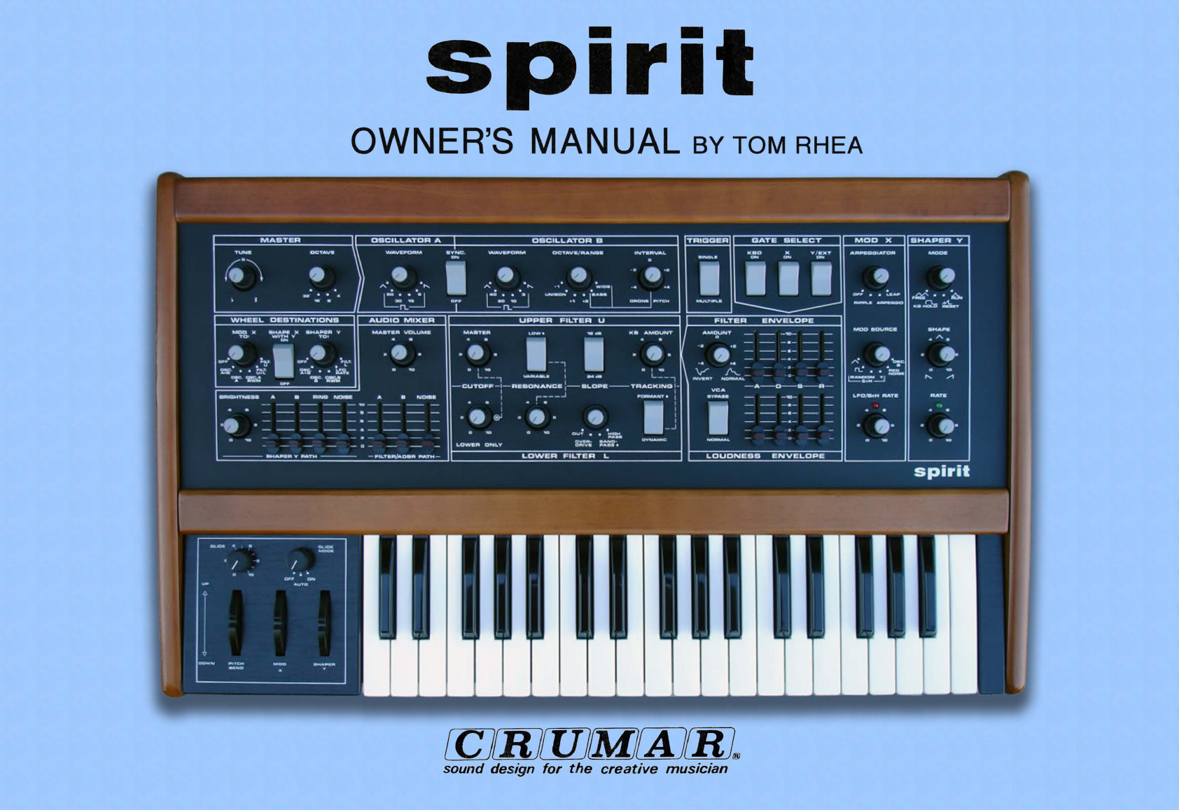
spirit
OWNER'S
MANUAL
BY TOM RHEA
reJrm[J)JfMJrAJ[KL
sound
design
for
the
creative
musician

AUDIO
HOOKUP D.
Continue
to
GETTI
NG
A
SOUND/TUNEUP
section
of
this
manual.
GETTING
A SOUND/TUNEUP
BEFORE
POWERING
UP
THE
SPIRIT,
CHECK
THE
PLATE
ON
THE
REAR
PANEL
FOR
THE
APPROPRIATE
OPERATING
VOLTAGE
(117
Volt
Model
is
for
use
in
U.S.A.).
DO
NOT
CONNECT
A
117
VOLT
MODEL
INTO
EUROPEAN
(220
Volts)
MAINS
WITHOUT
AN
APPROPRIATE
ADAPTER.
THE
FOLLOWING
IS
A
SOUND
CHECK/TUNEUP:
A
QUICK
AND
SURE
WAY
TO
GET
A
SOUND
FROM
THE
SPIRIT.
AFTER
CHECKING
THE
SPIRIT
FOR
APPROPRIATE
OPERATING
VOLTAGE,
DO
THE
FOLLOWING:
FIRST ...
Do
the
following
to
"prepare"
the
Spirit:
A.
Plug
the
Spirit
power
cord
into
a
conventional
power
outlet.
1.
(Follow
instructions
in
AUDIO
HOOKUP
section
of
the
manual.)
B.
Connect
the
ADSR/MIX
AUDIO
OUT
jack
on
the
Spirit
rear panel
to
your
amplifier
input.
The
Spirit
output
is
high level.
2.
Turn
all
Spirit
rotary
pots
(smooth
turning
knobs)
to
12
o'clock
position
Choose
the
least sensitive
amplifier
input,
probably
marked
"high
level."
Keep
your
amplifier
volume
knob
to
zero
"a"
to
avoid
connection
thump.
--"straight
up."
3.
Switch
all
rotary
switches
fully
to
the
left.
4.
Switch
all
rocker
switches
down.
5. Push all slidepots
fully
down.
C.
Flip
the
power
switch
(near
power
cord)
on
the
Spirit's
rear panel
up
(on).
6. Center
the
PITCH
BEND
wheel, and move
the
MOD
X and
SHAPER
Y
wheels
fully
back
toward
you.
PREPARATORY
PATTERN
~
______
~M~A~S~T~E=R~
______
~Ir--=O~S~C~I=L=L~~~T~O~R~A~41
____________
~O=S=C~I~L=L~~~T=O~R~B~
__________
--1
\
TRIGGER
t-
__
G_A_T_E
__
S_E_L_E:;;.;C;;;,.T~---I
TUNE
OCTAVE
WAVEFORM
SYNC.
WAVEFORM
OCTAVE/RANGE
INTERVAL
KBO
x
ON
V/EXT
ON
BINCILE
•
.0. }
A·.O
..
~
[)
~.O.
,~.·.O.
~··I
::
9=
~~b~~,==~~~=32~.=,==.=:=.=4~h~~~~~50~3~~~~:5~8~1~~~O!iF====~~~40~~~~~~,~~~3~1
~~UN='B=O=N=.;==:~2r~BA~5~5~~O~A~ON~E~P='T=CH=d
WHEEL
OESTINATIONS
AUDIO
MIXER
UPPER
FILTER
U
FILTER
ENVELOPE
S
DDD
MULTIPLE
• • •
.0· 0 0 o
...
e'
/
'M~N'
=
1=1=:=1-1=
•
L"_,
_
••
c.--:
....
·
Q_',
\
,~q6.c
1
=~=
-CUTOFF-I-RESONANCE
II-SLOPE--TRACKING
1-
-A-O-S-R-
1 1
=A
·oj
·6-·-~
0
~O_uJ
'OVPABB
I
1;~;11
o
'10
0
10
au'..
-HIGH
-1-
-a-
- -
OVEA_
BA':~~B
DYNAMIC
NORMAL
- -
-0-
- -
LOWER
ONLY
DAIVE
PAsa
*
MOD
X
SHAPE
X
BHAPER
Y
TO:
WITH
Y
TO:
ON
·0·
0
·0·
OFF
FILT.
OFF
FILT.
• • u
••
L
~!'i'
• •
r.~Ll·
'l~5'
• •
I:.';..~E
ole.
T..5;:
o:c.
~'W.:
OFF
BRIGHTNESS
A A B
NOISE
B
RINO
NOIBE
4
."
-1-1-1-1-'0
-1-1-1-
-
--
---
---
-8-
--
----
--------,,------
.Q. :
BHAPER
Y
PATH
FILTEFI/ADSR
PATH
LOWER
FILTER
L
LOUDNESS
ENVELOPE
MOD
X
ARPEOGIATDR
.0.
OFF
• •
LEAP
RIPPLE
ARPEOGIO
MOD
SOURCE
LFO/B+H
RATE
BHAPER
Y
MOOR
.0
.
F",·
•
~
rL
Nt..
KS
HOLD
RESET
SHAPE
-."
aOB
o
'0
RATE
_ • B
aO-
o
'"
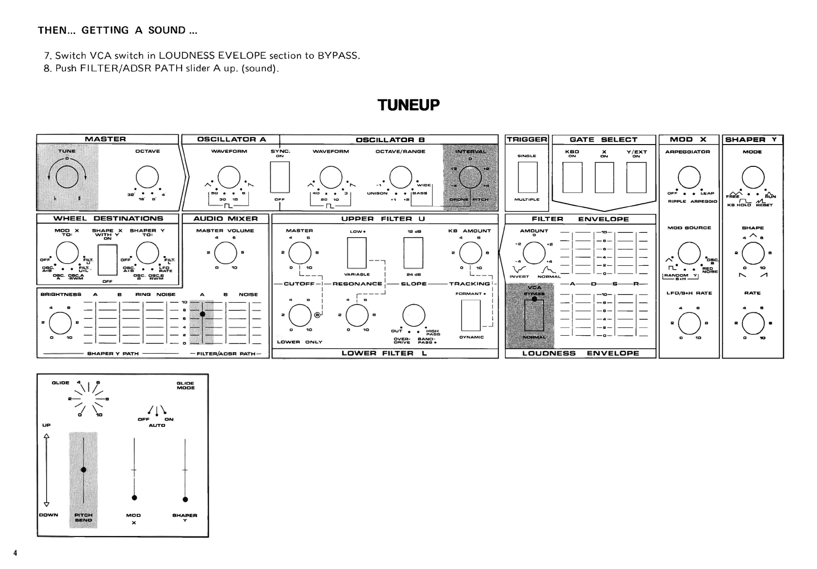
Rotary pots to 12 o'clock. Rotary switches
to
left. Rocker switches down. Sliders down.
This
Preparatory
Pattern produces
no
sound.
It
is
simply
an
easily remem-
bered
starting
point.
3
4
THEN
...
GETTING
A SOUND ...
7.
Switch
veA
switch
in
LOUDNESS
EVELOPE
section
to
BYPASS.
8. Push
FILTER/ADSR
PATH
slider A
up.
(sound).
OCTAVE
.0.
MOD
X
TO:
SHAPE
X
SHAPER
V
WITH
V
TO
:
ON
·0·
OFF
F.LT.
• • u
~-W-
::.t!i~·
·
,
o:c
.
~~~
D
OFF.
0
~OLT.
• • L
2.,!~
.
• •
~';.~E
asc
.
csc
.s
B
AWM
BRIGHTNESS
A B
RING
NOISE
o
SHAPER
V
PATH
GLIDE
;\1
~
R-
-8
//
\'
D
1D
OFF
ON
UP
AUTO
~
1
WAVEFORM
·0·
A.
"-
. .
I"D_
••
_SI
LO~
rL
AUDIO
MIXER
MASTER
VOLUME
o
A B
NOISE
-FILTER/ADSR
PATH-
aLlDe
MODI!
DOWN
MOO
BHAPER
)(
y
TUNEUP
SYNC.
WAVEFORM
o
14D
_
••
~
L
010
rL
MASTER
KB
AMOUNT
Q-
0--,
0
L
__
,
VARIABLE
I
24
dB
L
__
,
CUTOFF
-1-
RESONANCE
:--
SLOPE
---
TRACKING
I
I I
I ,
___
-.J
oJ
Os
LOWER
ONLY
.0.
OUT
• •
HIGH
PASS
OVEA-
BANO
-
DAIVE
PASS.
GATE
SELECT
KBD
)(
Y /
EXT
ON
o
000
-1-1-"'-
-1-1-
8-
I
1===
-
--
-D-
NORMAL
-A--O--S--R-
MOD
X
ARPEGOIATDR
.0.
OFF
• •
LEAP
MOD
SOURCE
LFD/B+H
RATE
o
SHAPER
Y
MODE
.0
.
F~·
•
~N
rL
NI...
KD
HOLD
AESET
SHAPE
4AS
o
RATE
o

NOW... TO TUNE THE SPIRIT...
BEFORE
TUNING
ALWAYS
CHECK
TO
SEE
THAT
THE
PITCH
BEND
WHEEL
IS
CENTERED.
9. Depress
the
key
you
want
to
match
and
tune
using
the
TUNE
control
in
the
MASTER
section.
You
may
want
to
select a
brighter
sound
for
tuning;
to
do
so,
use
the
OSCILLATOR
A
WAVEFORM
switch.
10
. Push
FILTER/ADSR
slider B
(next
to
A)
up.
11. Use
the
OSCILLATOR
B
INTERVALcontrol
to
produce
beatfree
tuning
between
Band
A.
(Note:
Osc B
is
presently
one
octave
lower
that
A.
Change
OCTAVE/RANGE
to
UNISON
to
match
pitches.) Once again,
you
may
want
to
Iisten
to
a
brighter
waveform;
to
do
so,
change
the
WAVEFORM
switch
for
Oscillator
B.
When
you
start
from
the
Preparatory
Pattern
it
is
easy
to
get a sound:
switch
VCA
to
BYPASS
and raise
the
A slider. When
tuning,
tune
A
first
using
the
MASTER
TUNE
control,
then
tune
B relative
to
A using
the
I
NTERVAL
control
and
OCTAVE/RANGE
switch
.
For
best
signal-
to
-noise
ratio,
place
MASTER
VOLUME
high
(at
least 5).
use reasonalby high slider
positions
(at
least
6).
and
adjust
your
amplifier
loudness
to
a
comfortable
listening
level.
SOUND CHARTS
THIS
SECTION
SHOWS
YOU
HOW
TO
CREATE
SOUNDS
EASILY
BY
DUPLICATING
SOUND
CHART
SETTINGS
ON
THE
CONTROL
PANEL
OF
THE
SPI
RIT,
AND
HELPS
YOU
LEARN
THROUGH
EXPERIMENTATION.
Unlike
the
traditional
arranger,
who
chooses
from
a
group
of
instruments
with
somewhat
fixed
characteristics,
the
synthesist
is
confronted
by
a
continuous
spectrum
of
instrumental
and
non-instrumental
sound
textures.
Because
the
sounds
of
the
synthesizer are
not
as
fixed
and
well-known
as
many
other
instruments,
we have developed a
notation
system
that
shows
what
the
front
panel
of
the
instrument
looks
like
when a
particular
sound
is
produced
- -
the
sound
chart.
A sound
chart
is
only
an
approximation.
To
get
the
most
from
these sound charts several ideas
may
be
helpful:
PREPARATORY
PATTERN
~
________
~_A
__
S_T_E_R
________
~I~_o==S=C~I=L=L=~~T~O~R~A~_~r
____________
~O~S=C~IL~L~~~T~O~R~B~
__________
~
\'
TRIGGER
~----------------~
GATE
SELECT
TUNE
OCTAVE
'NAVE
FORM
SYNC
.
VtlAVEFDRM
ON
OCTAVE/RANGE
INTERVAL
KBO
X
ON
v /
eXT
ON
-
_0.
}
"-.0:,,
[)
"-.0.·,,
.,-0.
~'OE'
I
::0
1
~:
• • I
50
_,.
._
B I I
40
_.
._
3 I
UN,aON·..
l
-sAa"
~~
,
~~,;=~~~~3~2~
'
='B~
'
=B~
'
=4~!J~==~
~
~3~~
~
~~==~OhiF====~~~~~0nL~'
~
~~======.='==
·
~~'
I
~~~~O~R~O_~=P'T=C=H=d
1;1
000
WHEEL
DESTINATIONS
AUDID
~IXER
UPPER
FILTER
U
FILTER
ENVELOPE
MOD
X
SHAPE
X
BHAPER
V
TO
:
WITH
V
TO:
ON
-0· 0-0·
O~F
F"-T
.
OFF
FILT.
• • u
••
L
~
.
• •
~,!-~
.
i'ffi
' • •
~~~E
a.c
.
oac
.A
oec
.
Olle
.•
A ·
AWM
a
RWM
.,...
a
'0
BRI[JHTNEBa
A 8
RING
NOIBE
A B
NOISE
..
0
4
-B
a 1
111
:
111
-
--
--
--
-4-
---
---
010
________
R
______
_
-
--
--
--
-0-
--
---
IIHAPI!R
V
PATH
FILTER/ADBR
PATH
MASTER
4 - B O
LOW.
o'~d"
KB
..
A.O~NT
I
AM"UNT
-1
-1-"'-1-1-
II
0 B -
-i
~
0B
::
0
~~
1
~~~
o
l
~O_1
VARIABLE
I
24aa
0
L:_,
I~T
"!;;;;-AL-
_
-0-
__
-CUTOFF-I
-
RESDNANCE
I
I-SLOPE--TRACKING
1-
-A-D-B--R-
1 1
~A
·6j ·
6-·-"
.0.
'·0-"]
'OVPASS
I
1~11
·
~
·
~
-'
..
,-
1
ovER-
BA~~B
O'l'NAMIC
NORMAL
- -
-0-
- -
OICttVE
PABB.
LO\NER
ONLY
LOWER
FILTER
L
LOUDNESS
ENVELOPE
Rotary pots
to
12
o'clock.
Rotary switches
to
left.
Rocker switches down. Sliders down.
~OD
X
ARPEOCIIATOR
RIPPLE
AAPlEOOlO
MOO
BDURCI!
LFO/B+H
RATI!
a ....
BHAPEA
Y
MOO.
SHAPe.
...
-
"0-
o
10
RATE
..
-.
"0-
o
10
5
6
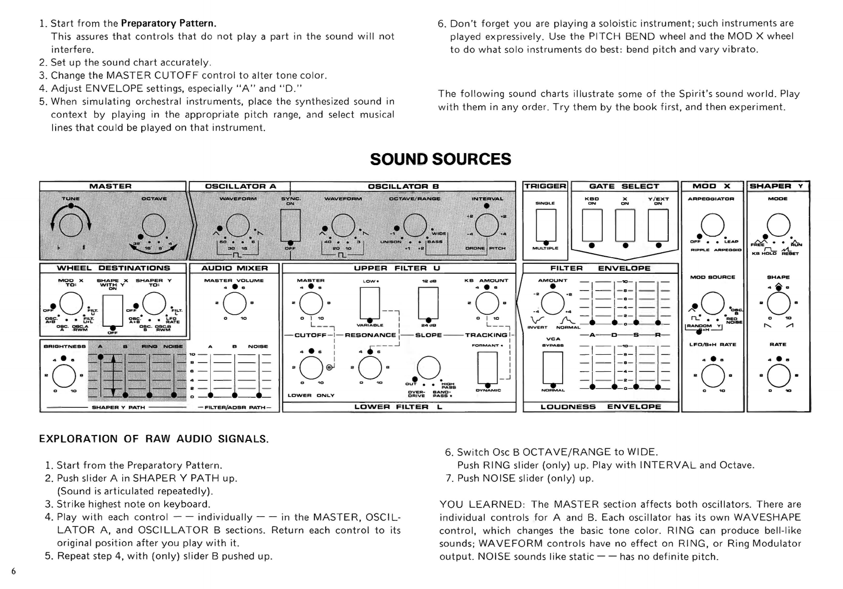
1.
Start
from
the
Preparatory
Pattern.
This
assures
that
controls
that
do
not
playa
part
in
the
sound
will
not
interfere.
2. Set
up
the
sound
chart
accurately
.
3. Change
the
MASTER
CUTOFF
control
to
alter
tone
color.
4.
Adjust
ENVELOPE
settings, especially
"A"
and
"D."
5. When
simulating
orchestral
instruments
, place
the
synthesized sound in
context
by
playing
in
the
appropriate
pitch
range, and select musical
lines
that
could
be
played
on
that
instrument
.
6.
Don't
forget
you
are
playing
a
soloistic
instrument;
such
instruments
are
played expressively. Use
the
PITCH
BEND
wheel and
the
MOD
X wheel
to
do
what
solo
instruments
do
best: bend
pitch
and
vary
vibrato.
The
following
sound charts
illustrate
some
of
the
Spirit's
sound
world.
Play
with
them
in
any
orde
r.
Try
them
by
the
book
first,
and
then
experiment
.
SOUND SOURCES
MOD
X
SHAPE
X
SHAPER
V
TO:
WITH
Y
TO:
ON
OF'
0
~'CT
.
0
OF'
0
"'CT
.
• • u
••
L
Dac
. • •
FILT.
asc
. • •
LFO
A+a
U+L
A+a
RATE
cae
.
oeC
.A -
CBC
.
OSC.a
A .
AW'M
a
AWM
OFF
BRIGHTNESS
A B
NOISE
a------
4------
a-
~
---
:=1=1=1=
_
......
__
.......
0 -
--
--
-
-
FtL.TER/ADSR
PATH-
EXPLORATION
OF RAW
AUDIO
SIGNALS.
1.
Start
from
the
Preparatory
Pattern.
2. Push slider A in
SHAPER
Y
PATH
up.
(Sound
is
articulated
repeatedly).
3.
Strike
highest
note
on
keyboard.
MASTER
KB
AMOUNT
-6·
0--'
10
aOs
0 1
10
o j .,o
L
__
-,
VARIABLE
I
24
d B L
__
,
TRIGGER
SINGLE
GATE
SELECT
r---------~
KBD
x
ON
V/EXT
ON
oD
DD
MULTIPLE
• • •
-A-
~
-O-S-R-
-CUTOFF
-1-
RESONANCE
:-
SL.OPE
--
TRACKING
1-
..
·a i 4
.~--~
FOoAMANT.
i
"O~~s
=I
=f-:=l=l=
aO~
aOs
0 j
=1_=:===
• .
_1-
-2-
__
0.,0
OUT
• •
;;:'::"°aMs
-e-
0-
__
OVEA
-
BAND-
DYNAMIC
NORMAL
LOWER
ONLY
DAIVE
"Asa.
6.
Switch
Osc B
OCTAVE/RANGE
to
WIDE.
MOO
X
SHAPER
Y
I-----------i
ARPEOGIATOR
.0.
OFF
• •
LIEAP
MOD
SOURCE
LFD/B+H
RATE
4
...
aOB
MODE
.0
.
F",·
•
~
rL
Nt.
KB
HOLD
Re..,.
SHAPE
-6-
o
RATE
Push
RING
slider
(only)
up.
Play
with
INTERVAL
and Octave.
7. Push
NOISE
slider
(only)
up
.
4. Play
with
each
control
- -
individually
- -
in
the
MASTER,
OSCI
L-
LATOR
A,
and OSCI
LLATOR
B sections.
Return
each
control
to
its
original
position
after
you
play
with
it.
YOU
LEARNED
:
The
MASTER
section
affects
both
oscillators.
There
are
individual
controls
for
A and B. Each
oscillator
has
its
own
WAVESHAPE
control,
which
changes
the
basic
tone
color
.
RING
can
produce
bell-like
sounds;
WAVEFORM
controls
have
no
effect
on RI
NG,
or
Ring
Modulator
output.
NOISE
sounds
like
static
- -
has
no
definite
pitch.
5. Repeat step 4,
with
(only)
slider B pushed
up.

MASTER
OSCILLATOR
A
TUNE
OCTAVE
WAVEFORM
WHEEL
OESTINATIONS
AUOIO
MIXER
MOD
X
SHAPE
X
SHAPER
Y
MASTER
VOLUME
TO:
\NITH
Y
TO:
ON
·0·
D·O.
OFF
FILT
.
OFF
FILT
.
• • U
••
L
~!ii
'
• • C':l'
~':5
'
• •
~~~e
esc
.
OSC
.A
esc
.
OSC
.S
A ·
RWM
B
RWM
BRIGHTNESS
A B
RING
NOISE
A B
NOISE
·6·
11
l' 1-1
~
ttl
--------2------
'0
--------0-
____
_
BHAPER
Y
PATH
-
FIL.TER/ADSR
PATH-
FAT FILTER
SYNC
.
o
OSCILLATOR
B
WAVEFORM
"'.0.·
.....
140
_.
._
3 I
L01~
n...
UPPER
OCTAve
/
RANGE
MASTER
l.OW
e
Adjust
to
unison
,
INTE
VAL
•
KB
AMOUNT
[3-
-;
0
00'
-6-
o J
10
L
......
_-,
VARIA.LS
I :
24
c:t
B L
__
,
';--
CUTOFF
:-I-
RESc)NANCE
1-, -
SL.OPE
--
TRACK
ING
1-
" < r " I
I '
r~--
J
I=ORMANT..
I
< 4 • • I 4 a I
'Q~
.Q.
J)o"""
OJ
PASS
OVER
·
BAND-
OYNAMIC
DRIVE
PASS
..
LOWER
FILTER
L
EXPLORATION
OF
GATING
AND
UPPER
FILTER
FEATURES.
1.
Play...
(no
sound).
Switch
GATE
SELECT
KBD
switch
ON.
Play!
2.
Try
GATE
SELECT
switches
individually
and in
combination.
MOO
X
SHAPER
Y
ARPEGGIATDR
MODE
o .0.
OFF
• •
LEAP
.0.
/"'../"..
••
A..
FReE
RUN
MULTIPLE
RIPPLE
ARPEGGIO
rL
N'l..
KS
HOLO
RESET
FILTER
ENVELOPE
MOD
SOURCE
SHAPE
AM~UNT
-1-
1
-"'-1-1-
'·0·
-1-
-9-
1
- -
- -
-6-
--
V A t
t:=
INVERT
NORMAL
-6-
o
-A-O-S-Fl-
VCA
LFO/B+H
RATE
RATE
BYPASS
=1=1
=:=r=l=
O
-I-
I
-e-
--
=~=l=:=I===
==
NORMAL
- -
-0-
--
-
LOUONESS
ENVELOPE
3. Place
(only)
KBD
switch
ON.
4.
Hold
key
and listen.
Switch
UPPER FI L
TER
RESONANCE
switch
between
VARIABLE
and
LOW
and compare.
Return
to
VARIABLE
position
.
YOU
LEARNED:
Must
have one
GATE
SELECT
switch
ON
to
articulate
sound in FI L
TERjADSR
PATH.
Sound
can
be
gated
by
MOD
X,
SHAPER
Y,
or
keyboard.
5.
Experiment
with
LOWER
FI L
TER
RESONANCE
control.
Return
to
10.
6.
Alter
setting
of
MASTER
CUTOFF
. Play.
Return
to
original
position.
7.
Do
same
with
LOWER
ONLY
CUTOFF.
Filter
resonance affects sound greatly. Resonance
of
UPPER
F)L
TER
is
varied
by
(lower)
RESONANCE
control
when
VARIABLE
position
selected
above.
MASTER
CUTOFF
sets
filter
"starting
point."
LOWER
ONLY
CUTOFF
inoperable
when
Lower
Filter
is
OUT
(look
again).
7

8
50
MASTER
TUNE
OCTAVE
I
.0.
·0·
"'.
•
r-...
31ii!" • •
a'
"IB'
s'
I
~o
_.
._
6 I
LO~
rL
DESTINATIONS
AUDIO
MIXER
MASTER
VOLUME
BRIGHTNESS
A B
RING
NOISE
A B
NOISE
UP
DOWN
BHAPER
V
PATH
Ii".
-
FILTER/ADBR
PATH-
GLIDE
MODE
OFF
ON
I f
PITCH
BEND
MOD
)(
AUTO
BHAPER
Y
MOD WHISTLE
OSCILLATOR
B
TRIGGER
GATE
SELECT
MOO
X
SHAPER
Y
WAVEFORM
OCTAVE/RANGE
'
:6:
[]
ODD
DRONE
PITCH
MULTIPLE
••
o
·0·
·0·
A..
• •
'"
-1.
•
WIDE
1
40
_.
-_
:3
1
UNISON..
BASS
L01~
rL
ARPEGIGIIATOR
.0.
OFF
• •
LEAP
ARPIEOQID
MOOE
.0
.
F~
••
~N
rL
,vi...
KB
HOLD
REBET
UPPER
FILTER
U
FILTER
ENVELOPE
MASTER
KB
AMOUNT
AMOUNT
_
__I_~_
-- _
_Qo
0--,
0
_Qo
;6~
I
I~~~I=I=
L
__
--,
VAR'ABLE
1
24
dB
L
__
,
'NVERT
NO"MAL----~o-EE
-CUTOFF-
I-
RESONANCE
II-SLOPE--TRACKING
1-
-A--O--S--R-
I I
VCA
·OJ
-6-·-~
.0.
'OOO.OOJ
0 I
1~r=I=
OUT
••
H'GH
='
t l=t
OVER-
BA':~~S
DYNAMIC
NORMAL
-
--
-0-
--
-
SHAPE
·6·
RATE
LOWER
ONLY
DRIVE
PASS.
LOWER
FILTEI=I
L
LOUDNESS
ENVELOPE
EXPLORATION
OF X
MODULATIONS
1.
Play.
MOD
X wheel
controls
vibrato
amount.
2.
Adjust
vibrato
speed
with
LFO/S+H
control.
3.
Try
all
MOD
X
TO:
positions;
for
each,
move
MOD
X wheel
fully
forward
and back.
4. Repeat step 3
for
each
MOD
SOURCE
position.
YOU
LEARNED:
MOD
SOURCE
determines
the
shape
of
modulation
signal;
MOD
X wheel
controls
the
amount;
MOD
X
TO:
determines
where
the
signal
goes.
GLIDE
smoothes
pitch
transitions.
Osc B
TUNE
WHEEL.
MOD
X
SHAPE
TO
:
WITH
V
ON
OFF·
0
~'CT
.
D
'1.'!~
•••
~'!-~
otIC
.
08C
.A
A ·
RWM
BRIGHTNESS
A B
BHAPER
V
PATH
-
FILTER/ADSR
PATH-
GLIDE
-:\
I
/~
R-
-8
/.
\'--
D
10
UP
~
I
DOWN
PITCH
BEND
IMPORTANT!
DFF
DN
MDD
X
AUTD
OLh::J&
MqOE
MASTER
4 • 6
"OS
o I
.,0
SYNC
+1
KB
AMOUNT
TRIGGER
t-_G_Ai._T_E_S_E_L.,;;;E..;;C;.,.T_--i
MOO
X
o
ODD
MULTIPLE
••
ARPEGOIATOR
.0.
OFF
• •
LEAP
RIPPLE
~P.ClOIO
I
.
'
~
. . .
......
",
FIL.TER
ENVEL.OPE
.sO."
-1-
-6-
- -
=1='
=:=
==
·0·
-4
+4 _
__
_
..
_
__
_
/".:::
• •
0:
0--
; 0
-Q-
L_-
t
VARIABLE
I
24
dB
L_
- i
-
CUTOFF
- I-
RESONANCE
:-
SLOPE
--
TRACKING
I-
AM~UNT
-1-I-G
-l1
-=
~U"C.
V
~
0
~
••
::l~?8E
INVERT
NOAMAL~--l=
'"--...",~--"
-A-O--S-R-
I I
I
.-
- - -
.-J
FORMANT.
I
veA
LFDI&+H
RATE
-oJ
-0'
o",Qo"_
D-J
PASS
LOWER
ONLY
OVEA-
BANO-
DAIVE
PAa
••
DYNAMIC
L.OWER
FIL.TER
L.
L.OUONESS
ENVEL.OPE
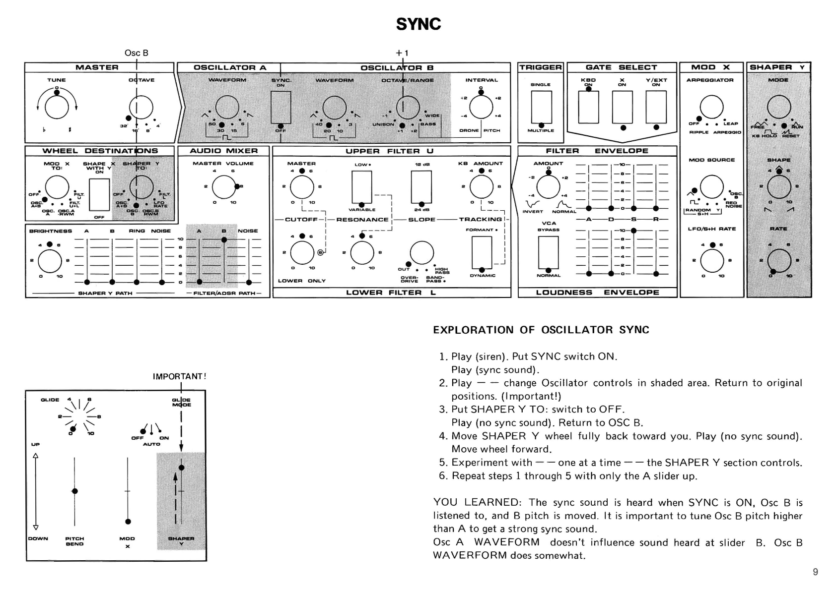
EXPLORATION OF OSCILLATOR SYNC
1. Play (siren).
Put
SYNC
switch
ON.
Play
(sync
sound).
2. Play - - change
Oscillator
controls
In
shaded area.
Return
to
original
positions.
(Important!)
3.
Put
SHAPER
Y
TO
:
switch
to
OFF
.
Play
(no
sync sound).
Return
to
OSC B.
4.
Move
SHAPER
Y wheel
fully
back
toward
you.
Play
(no
sync sound).
Move
wheel
forward.
5.
Experiment
with
- - one at a
time
- -
the
SHAPER
Y section
controls.
6. Repeat steps 1
through
5
with
only
the
A slider
up
.
YOU
LEARNED
:
The
sync sound
is
heard
when
SYNC
is
ON,
Osc B
is
listened
to,
and B
pitch
is
moved.
It
is
important
to
tune
Osc B
pitch
higher
than
A
to
get a
strong
sync sound.
Osc A
WAVEFORM
doesn't
influence
sound heard
at
slider B. Osc B
WAVERFORM
does
somewhat.
9

10
OSCILLATOR
A
WAVEFORM
·0·
A
"-
. .
I
eo
_
••
_ e I
LO~
rL
AUDID
MIXER
MASTER
VOLUME
BRIGHTNESS
A B
RING
NOISE
-l-'-§l-'O
80
....
8= -
l=-=:
S,
---------
..
~
0.,0
-
__
_
___
a,
-
--
--
- 0 ,..
,;
~
,
UP
BHAPER
Y
PATH
aLICE
;\I/~
8-
-B
I'\:
PITCH
BEND
'1\
OFF
ON
AUTO
--~
..
GLIDE
MODe:
SHAKE SHAPE
OSCILLATOR
B
TRIGGER
GATE
SELECT
~------------------~
SYNC
.
WAVEFORM
OCTAVE/RANGE
INTERVAL
D
DD~
MULTIPLE
-. .
UPPER
FILTER
ENVELOPE
ARPEG(JIATOR
.0.
OFF
• •
LEAP
~IPPL.
ARPII!!DGIO
SHAPER
V
MODE
.0.
F~.·
~
rL
Nt..
KB
HOLO
RESET
KB
AMOUNT
'0
0
0--
,
[]
L
__
j
VARIABLE
I
24(:111
L _ _ ,
SHAPE
..
A.
'
-CUTOFF
- 1-
RESONANCE
:-
SLOPE
--TRACKING
I-
I I
VCA
-A---O---S---R
--
·dJ
·o·-~
BYPA8S
D
.0.
OUT
••
;;:~GBHS
OVEA-
BANO·
NO~MAL.
RATE
LOWER
ONLY
OAIVE
"ASS.
LO\NER
FILTER
L
LOUDNESS
ENVELOPE
EXPLORATION
OF SHAPER Y
VIBRATO
AMOUNT/RATE
CONTROL
1.
Hold
any
key
down.
(Immediate
vibrato).
2.
Switch
SHAPE
X
WITH
Y
SWITCH
ON.
Play.
(Vibrato
amount
is
shaped
by
Y).
3.
Switch
SHAPE
X
WITH
Y
SWITCH
OFF.
4. Move
SHAPER
Y wheel
to
midpoint.
Play.
(Vibrato
rate
is
increased
by
V).
5.
Try
different
SHAPER
Y wheel and
LFO-S+H
RATE
settings; experi-
ment.
6.
Adjust
MOD
X wheel
for
desired
vibrato
depth
. Repeat step
number
2.
YOU
LEARNED:
MOD
X wheel determines
the
maximum
depth
of
modula-
tion
routed
to
MOD
X
TO:
switch.
SHAPE
X
WITH
Y
switch
shapes
within
that
maximum.
Shaper Y alters
MOD
X rate when
SHAPER
Y
TO
:
switch
is
toLFO
RATE.
The
Y wheel sets fastest rate;
LFD/S+H
RATE
sets slowest (beginning) rate.
MASTER
TUNE
OCTAVE
WHEEL
DESTINATIONS
Mdb
·,x
TO'
: ':'
SHAPE
x
SHAPER
Y
WITH
Y
TO
:
ON
'1
00
'"
~,{!
• •
"l'.
FlLoT
OF!"
FILT
u
••
L
~l.c
I
~~5
• •
~~!?e
osc
esc
.s
B
AWM
OFF
OSCILLATOR
A
WAVEFORM
AUDIO
MIXER
MASTER
VOLUME
BRIGHTNESS
A B
RING
NOISE
A B
NOISE
UP
&HAPER
V
PATH
-
FILTER/ADSR
PATH-
GLIDE
;\
I
1:-
Ii!-
-8
/.
\'
0
10
I
r
PITCH
BEND
'1\
GLIDE
MODE
OFF
ON
AUTO
BHAPER
y
SYNC
.
o
OFF
SAMPLE & HOLD
OSCILLATOR
B
WAVEFORM
OCTAVE
/
RANGE
",e.O
..
"
.,e.O.
~'OE
[:
0
..~
UNISON..
BASS
_0
.,0
rL
UPPER
FILTER
U
INTERVAL.
KB
AMOUNT
4 e s
TRIGGER
~~~~~~----~
SINGLE
o
MULTIPLE
FILTER
ENVELOPE
..
."
-1-
-B-
--
O
=1
'=
1
=:=
==
·4
'4
•
MOO
X
ARPEGGIATOR
eO.
OFF
• •
LEAP
ARPEOGIO
SHAPER
Y
MODI!
eO.
F",
••
~N
rL
N'L
Ka
HOLD
RESET
0_-
'1
0
-OB
01_
01_
AM~UNT
-
-'-"'-~1-
-
---1-
2-
--
-
--
V
A_~
-
0-
_
INVERT
NORMAL
L
__
-,
V
ARIABLE
I
24
dB
L
__
-,
-
CUTOFF
-1-
RESONANCE
:-
SLOPE
---
TRACKING
I-
-A
---
O---S
--
-R
-
VCA
I 1
·oJ
·
o·
-~
"",Q._
IJ)
CJ
hl~r
8
OVER-
BANO-
CAlVE
PASS.
LOWER
ONLY
LOWER
FILTER
L
LOUDNESS
ENVELOPE
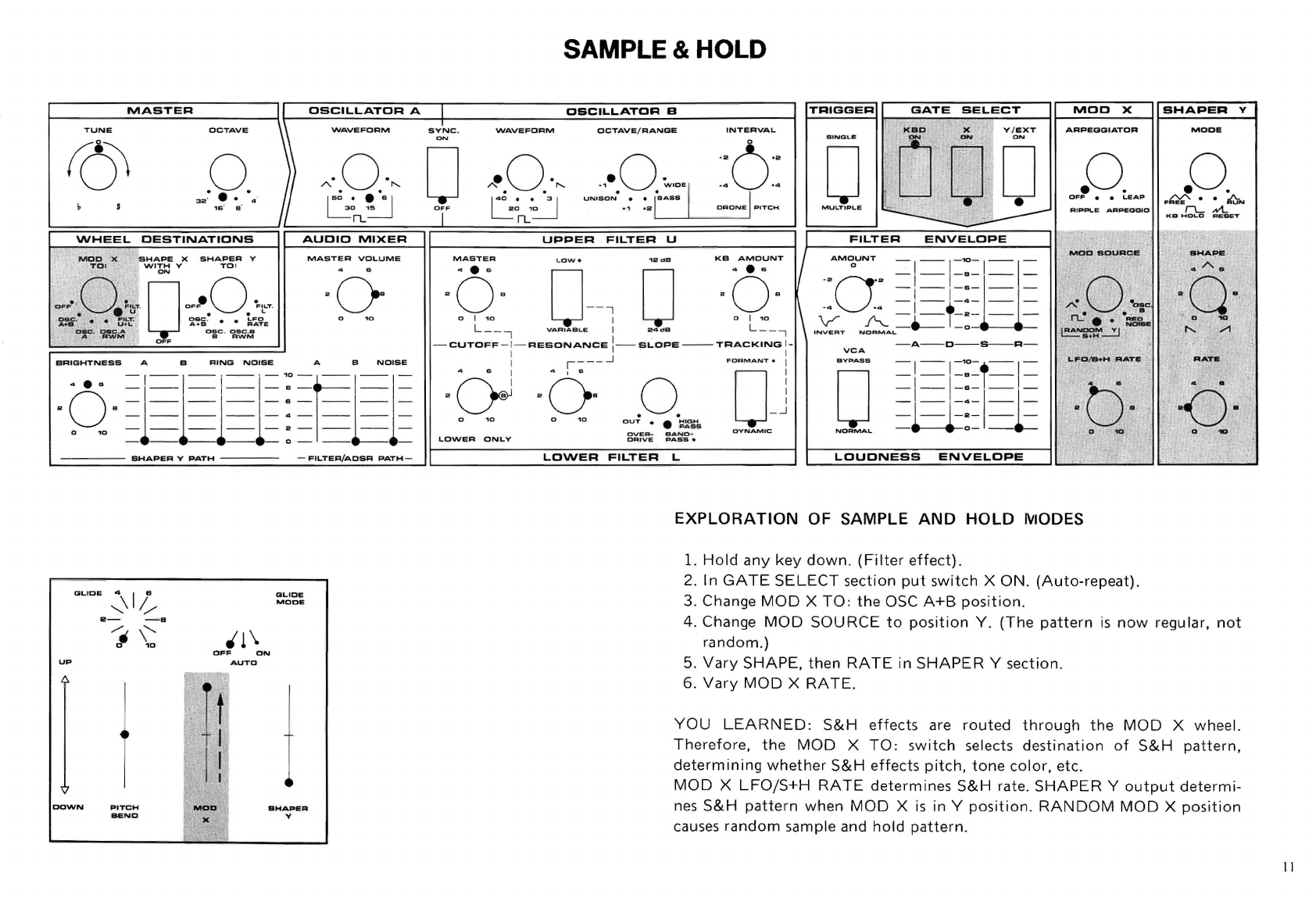
EXPLORATION
OF SAMPLE
AND
HOLD
MODES
1.
Hold
any
key
down
.
(Filter
effect).
2. In
GATE
SELECT
section
put
switch
X
ON
.
(Auto-repeat).
3. Change
MOD
X
TO:
the
OSC
A+B
position.
4. Change
MOD
SOURCE
to
position
Y.
(The
pattern
is
now
regular,
not
random
.)
5.
Vary
SHAPE,
then
RATE
in
SHAPER
Y section.
6.
Vary
MOD
X
RATE.
YOU
LEARNED
:
S&H
effects
are
routed
through
the
MOD
X wheel.
Therefore,
the
MOD
X
TO:
switch
selects
destination
of
S&H
pattern,
determining
whether
S&H
effects
pitch,
tone
color,
etc.
MOD
X
LFOjS+H
RATE
determines
S&H
rate.
SHAPER
Y
output
determi-
nes
S&H
pattern
when
MOD
X
is
in Y
position.
RANDOM
MOD
X
position
causes
random
sample and
hold
pattem.
11
12
MASTER
OSCILLATOR
A
TUNE
OCTAVE
WAVEFORM
.0.
32"
••
4"
1&
e"
A·.O.·
.......
150
_.
._
e I
LO~
rL
-
MIXER
MASTER
VOLUME
BHAPER
V
PATH
___
-
FILTER/ADSR
PATH-
GLIDE
-:\
I
~
UP
DOWN
2-
-8
/.
\"
D
10
1
PITCH
BEND
OFF
ON
AUTO
GLICE
MODE
PARALLEL
RECTANGLES
Adjust
OSCILLATOR
B
TRIGGER
GATE
SELECT
r---------------~
MOD
X
SHAPER
Y
SYNC.
WAVEFORM
OCTAVE
/
RANGE
o
OFF
·0·
A
.......
1
4';
_
••
_
·31
LO
1~
rL
ARPEGGIATOR
.0.
OFF
• •
LEAP
RIPPLE
ARPEGGIO
u
ODD
-.- .
MODE
.0
.
F~·
•
~N
"-
N1..
KB
HOLD
RESET
UPPER
FILTER
FILTER
ENVELOPE
MOD
SOURCE
SHAPE
KB
:
0·
U--,
[]
L
__
,
VARIABLE
I
24dB
L
__
,
·0·
o
"
/I
AM~UNT
-'-f"'-
-§
- ,-
-e-I_-
·~O·2
=--
_==:1--
V A
-t=I-~-r=-
- -
-0-
---
INVERT
NORMAL
-CUTOFF-
I-
RESONANCE
:-
SLOPE--
TRACKING
I-
I I
VCA
-A-O
-
S-R-
·bJ
·cs·-~
LOWER
ONLY
.0.
OUT
• •
HIGH
PASS
OVER-
CRIVE
BAND-
PASS.
FORMANT.
I
1J
J
LFO/B+H
RATE
RATE
BYPASS
=,
=1
=::=:~~
O
- 1-1=e--
=,=T=::=:
==
NORMAL
- -
-0-
--
-
LOWER
FILTER
L
LOUDNESS
ENVELOPE
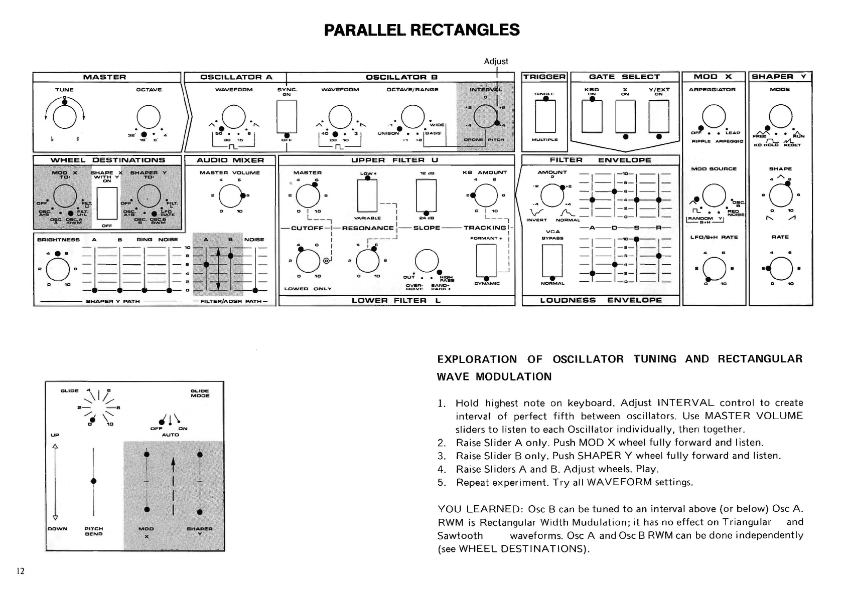
EXPLORATION
OF
OSCILLATOR
TUNING
AND
RECTANGULAR
WAVE
MODULATION
L
Hold
highest
note
on
keyboard.
Adjust
INTERVAL
control
to
create
interval
of
perfect
fifth
between
oscillators.
Use
MASTER
VOLUME
sliders
to
iisten
to
each
Oscillator
individually.
then
together.
Raise
Slider
A
only.
Push
MOD
X
wheel
fully
forward
and
listen.
Raise
Slider
B
only.
Push
SHAPER
Y wheel
fully
forward
and
listen.
Raise Sliders A and B.
Adjust
wheels. Play.
Repeat
experiment.
Try
all
WAVEFORM
settings.
YOU
LEARNED:
Osc B can be
tuned
to
an
interval
above
(or
below)
Osc
A.
RWM
is
Rectangular
Width
Mudulation;
it
has
no
effect
on
Triangular
and
Sawtooth
waveforms.
Osc A
and
Osc B RWM can be
done
independently
(see
WHEEL
DESTINATIONS).

MASTER
OSCILLATOR
A
TUNE
OCTAVE
'WAVEFORM
·0·
A.
."
150
_.
._
S I
L
O~
n...
WHEEL
OESTINATIONS
AUOIO
MIXER
MOD
X
SHAPE
X
SHAPER
Y
MASTER
VOLUME
TO
:
WITH
Y
TO
:
ON
OF'
0
~'LT
.
0
OF'
0
·F'LT
.
• • u
••
L
aBC
. • •
F.LT
.
esc
. • • L F O
A+e
U
+L
A . e
RATE
esc
.
oaC
.A
esc
.
csc
.s
A .
RWM
B
RW
M
OFF
BR
IG
....
TNESS
A B B
NOISE
SHAPER
Y
PATH
GLICE
::.\
I
1';-
aL.ICE
MODE
..
-
-B
/.
\"-
'1
\
0
10
OFF
ON
UP
AUTO
I j
r 1 •
DOWN
PITCH
MOO
SHAPER
BEND
X V
ARPEGGIO
OSCILLATOR
B
TRIGGER
I--_G=..:....A~T-=E=---.=S:..:E:..:L:..:E=C....:T_----l
b-_M...;,O,;;;..;;O;;,.....-,;.,X;...,.....j
SHAPER
Y
S Y
NC
.
WAVEFORM
OCTAVE
/
RANGE
INTERVAL
u
OD
D
AR
...
~
A,Td"
~.o
..
"
.,
..
0.
~'OE
.0.
~
o
•
._
:3
I
UNISON..
BAS
_
eD
1
~
n...
MULTIPLE
• •
F~
••
~N
IL.
Nt..
KB
HOLO
ReseT
MASTER
4 • S
a
O-
o I
10
L_ _ ,
I
I
a
(j
J
LOWER
ON
LY
UPPER
FILTER
U
0-
;0
V
AR
I
ABLE
I
24
dB
·cr
~
.0.
OU
T
••
=~0.rs
OVER
-
BANO-
DRi
v e P A
SS.
LOWER
FILTER
L
KB
AMOUNT
aO-
o I
10
6.
__
,
LOUONESS
EXPLORATION
OF MOD X
ARPEGGIATOR
1.
Play and
hold
a three-note
chord
in
middle
of
keyboard.
2.
Try
different
ARPEGGIATOR
modes
wh
i
le
holding
chord.
3. Push
LOUDNESS
ENVELOPE
slider R
to
"4."
Turn
FI LI
ER
ENVELOPE
AMOUNT
to
"+4."
4. Raise
NOISE
slider in
SHAPER
Y
PATH.
5. Change
LFO/S+H
RATE;
watch
X and Y
RATE
lights.
SHAPE
·6·
YOU
LEARNED:
The
Spir
it
will
make a sequence
of
notes played on
the
keyboard
when
the
ARPEGGIATOR
is
on. Octave changes
occur
in
the
ARPEGGIO
and
LEAP
modes.
Sound
produced
may
be
enveloped
by
FI
LTER
ENVELOPE
and
LOUDNESS
ENVELOPE
.
ARPEGG
IATOR
modes cause
SHAPER
Y
RATE
to
synchronize
with
LFO/
S+H R
ATE.
(Ex
ception
:
FR
EE
MODE).
13

14
SHAPER
V
PATH
GLICE
;.\
I
/~
UP
I '
DOWN
R-
-8
/.
\'-...
o "KJ
PITCH
BEND
CJLIDE
MODE
OFF
ON
MO
_D
X
AUTO
BHAPER
y
NOISE SCALE
TRIGGER
GATE
SELECT
MOO
X
ARPEGGIATOR
.0.
OFF
• •
LEAP
I
L.FO/S+H
RATE
LOUONESS
ENVELOPE
EXPLORATION
OF NOISE
AS
SOUND SOURCIE
l.
Play
keyboard
.
Turn
RESONANCE
to
" ]
0."
Play!
SHAPER
Y
MODE
.0.
F",
••
~
r-L
Nt..
KB
HOLD
RESET
SHAPE
·6·
o
10
RATE
2.
Compare
noise
pitc
h
to
Osc A
pitch.
Use
SI
'
ider
A
only,
then
NOISE
Slider
only.
3.
Hold
lowest
key
and
"tune"
noise
to
Osc A
pitch
using
MASTER
CU-
TOFF.
Adjust
keyboard
scale
(interva
l size) using
KB
AMOUNT
TRA-
CKING
control.
4. Play. Push
MOD
X wheel
forward
.
Note
position
of
MOD
X
TO
:
switch.
5.
Put
MOD
X wheel
fully
forward
. Change
MOD
SOURCE.
Play.
Vary
LFO/S+H
RATE
.
YOU
LEARNED:
Noise takes
on
the
pitch
of
fi
l
ter
cutoff
frequency
when
resonance.is
maximum.
KB
AMOUNT
TRACKING
causes
the
filter
cutoff
to
move,
or
"track"
the
keyboard.
Filter
modulations
sound
like
pitch
changes
when
filter
resonance
is
ma-
ximum.
(Because
the
cutoff
frequency
determines
pitch,
and
it
is
being
moved
.)
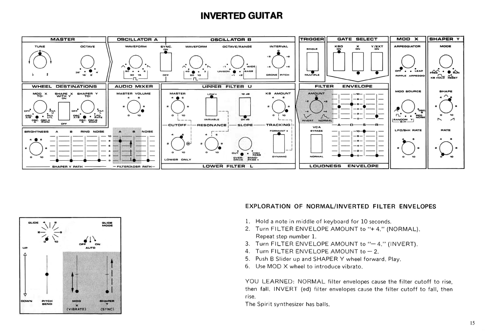
INVERTED GUITAR
~
________
~~
~
A
~
S~T~E
~
R
~
__
______
~I~~D~S~C~I~L~L~A~T~D~R~A~_I~
____________
~D=S==C~I=L=L~A~~~O~R~B~
____________
_1
\
TRIGGER
GATE
SELECT
r---
-
----
--~
MOD
X I
BHAPER
Y
r----
-'1
TUNE
OCTAVE
WAVEFORM
SYNC
.
WAVEFORM
OCTAVE
/
RANGE
INTERVAL
ARPEOGIATOR
MODI!
.0. )
A·
.0
..
"
0-
"0
"~""
0
~OO·I
.·
~~
~
t.
~
UN'
S
ON·
•
.,
[BASS
I
~~
b
~===I~==~
~~
3
~
2
='
~B
'
~8~4==~~
~~~~~
nL
~
~~~~0
~
j
~
F
==
==~~
R
O~nL~'~0~
~~~~=.~
'
~.
2~~~~~0~~0~N~E~P'=TC=M~
[]
ODD
MULTIPLE
••
.0.
O F F • •
LEAP
RIPPLE
AAP
.
OGIO
.0.
F~·
•
~N
rL
N'l.
KII
HOLD
RESET
-
\NHEEL
DESTINATIONS
AUDIO
MIXER
UPPER
FILTER
U
FILTER
ENVELOPE
MOO
X
SHAPE
X
SHAPER
V
MASTER
VOLUME
TO
:
WITH
V
TO
:
ON
OFF·
0
~'
"
T
.
DOFF.
0
·F'"T
.
OBC
.
·.
•
~'".::'
osc~.
•
tFO"
A.e
U +L A + B R A
TE
esc
.
esC
.A e s c .
CSC
.S
A ·
RWM
B
AWM
OFF
.'
BRIGHTNESS
A B
RING
NOIS
E • •
NOISE
4 B
-
I
-l-
'
~-'O
_
"
~
'.
,.
~
;
'
,
I
I-
·
-~
-1-
-8
_ -
I-
' :
.,
I
2
0e=
===
=:
,.'
~
.;
=
o
'0
- - - - - 2 - .:.:"..u
-1
-
- - - - 0
;-
-----1:-
,
~
UP
DOWN
SHAPER
Y
PATH
PITCH
BEND
'1\
OFF
ON
AUTO
Ie
( VIBRATO)
;:-
.
~
..
'"
..
'
GLIDe;
MODE
FILT
I!
R /
AOSR
PATH
'2.
"
KB
AMOUNT
/ .
"':;"P':;
N;'
MASTER
ROe
MOD
SOURCE
SHAPE
-0·
o I
.,0
o '0
O-
-i
0
-Q.
,
~
,,
~
t nt1
L
__
,
VA
RI
A
EIL
E I 2 4 d B L _ _ , lN
VE
RT: ..
"'IO
~
M
A
":-
--
-0
-
--
-
-CUTOFF
-i
-
RESONANCE
:
-SLOPE
--
TRACKING
i -
VCA
- A
--
O-
-
S-
-
R-
-dJ
·
d:-
-
~
o.;9"~
,.
"
:Q
"J
0
~
~I~E
O V
ER
-
II
AND
-
LFO/B+H
RATE
RATE
LOWER
ONLY
DR
IV
E
PAS
S .
LO\NER
FILTER
L
LOUDNESS
ENVELOPE
EXPLORATION
OF
NORMAL/INVERTED
FILTER
ENVELOPES
1.
Hold
a
note
in mi
ddle
of
keyboard
for
10 seconds,
2.
Turn
FI L
TER
ENVELOPE
AMOUNT
to
"+
4
."
(NORMAL)
.
Repeat step
number
1.
3, Turn FI LT
ER
ENVELOPE
AMOUNT
to
"-
4."
(I
NVERT),
4,
Turn
FI L
TER
ENVELOPE
AMOUNT
to
-2.
5. Push B
Slider
up
and
SHAPER
Y wheel
forward.
Play.
6. Use
MOD
X
whe
el
to
introduce
vibrato
,
YOU
LEARNED:
NORMAL
filter
envelopes cause
the
filter
cutoff
to
rise,
then
fal
l.
INVER
T (ed)
filter
envelopes cause
the
filter
cutoff
to
fall,
then
r
ise
.
The
Spirit
synthesizer has balls,
15

16
SYNTHESIZER
BASICS
The
synthesizer
offers
the
performer
new
ways
to
deal
with
the
properties
of
sound:
pitch,
timbre
(tone
color),
and loudness.
With
electronic
musical
instruments,
form
need
not
follow
function.
That
is,
the
physical
construction,
size
and
shape
of
the
synthesizer
doesn't
dictate
the
sounds
it
produces.
The
way
its
electronic
elements
are
connected,
controlled
and
calibrated
does.
The
early
versions
of
the
modern
synthesizer
were
modular.
This
type
has
separate
modules
- -
like
stereo system
components
- -
that
provide
independent
and
variable
control
over
sound
properties.
An
inexpensive
and
reliable
way
to
connect
these
modules
is
with
cables called
"patchcords."
Synthesizers
designed
specifically
for
live
performances
- - such
as
the
Spirit
- -
let
you
"patch"
together
sections
(modules)
of
the
instrument
using switches,
knobs,
and sliders instead
of
patchcords.
(Even
when
pat-
chcords
are
not
used, a
synthesizer
control
panel
setup
is
still
often
referred
to
as
a
"patch.
")
For
the
purpose
of
learning
about
synthesizers,
let's
continue
to
think
of
the
synthesizer
as
a
collection
of
modules
that
do
different
things,
and
require
patchcord
connection.
Since
sound
has
the
properties
of
pitch,
timbre,
and
loudness,
it
follows
that
the
synthesizer
has
modules
dealing
with
each
property:
SYNTHESIZER
SOUND
MODULES
The
synthesizer
manipulates
electronic
signals - -
sound
is
created
by
a
speaker.
Sound
starts
as
an
electronic
signal capable
of
driving
a speaker
--
an
audio
signal.
Not
surprisingly,
the
module
that
does
this
is
called
an
"au-
dio
signal
generator."
This
generator
is
sometimes
called
simply
a
"sound
sou
rce."
A
sound
source generates
the
unrefined
tone
or
noise
that
can be shaped
into
musical
sound.
Take
the
mouthpiece
of
a
trumpet
and
buzz
sounds using
your
lips - -
this
is
an
unrefined
sound
source!
The
timbre
module
on
most
synthesizers acts
somewhat
like
a
trumpet
mute
- - each
is
a
sound
modi-
fier.
The
loudness
module
is
another
modifier,
like
the
bell
of
the
trumpet.
The
pitch
module
of
the
synthesizer
is
a
sound
source
similar
to
the
lips,
mouthpiece,
and
column
lengths
that
make
trumpet
pitches.
We need
at
least
two
things
to
get
sound
from
a
synthesizer:
a
sound
source
and a speaker
to
translate
the
audio
signal
coming
from
the
sound
so
urce:
MINIMUM
AUDIO
"PATCH"
MONITOR
SOUND
SOURCE
AMP
&
~PITCH~r
~--
--·----
-
"m(
The
sound
produced
by
this
most
basic
of
"patches"
is
not
interesting.
The
sound
properties
are
static
- -
they
don't
change.
Now
let's
insert
the
tim-
bre
and loudness
modifiers
between
the
sound
source and
the
speaker:
SOUNO
SOURCE
SOUND
MODIFIER
PITCH
TIMBRE
SOUND
MOD
IFIER
LOUDNESS
MONITO'R
AMP
&
SPEAKER
/
The
path
from
sound
source
through
the
modifiers
to
the
speaker
is
called
the
"audio
signal
path."
Note
that
the
sound
source has
only
an
audio
output
since
it
actually
generates
the
audio
signal.
The
mod
i
fiers
have
both
an
audio
input
and
an
audio
output
since
the
signal
to
be
modified
passes
through
them.
Now
let's
use
the
appropriate
synthesize
r
terminology,
The
pitch-generating
module
is
called an
oscillator,
the
timbre-modifying
module
is
called a
filter,
and
the
loudness
modifie
r
is
called an
amplifier.
The
diagram
below
shows
these
synthesizer
modules
in
the
audio
signal,
path
tha
i establish a
pitched
musical
sound:
TYPICAL
AUDIO
SIGNAL
PATH
MODULES
SOUNO
SOURCE
SOUND
MODIFIER
SOUND
MODIFIER
OSCILLATOR
FILTER
J
AMPLIFIER
,I l
Modulation
Modulation
is
a change - -
typically
a
recurring,
or
repetitive
change.
Let's
consider
the
case
of
vibrato.
Vibrato
is
a
repetitive,
smooth
change above
and
below
a
"center"
pitch
.
The
VCO's
make
pitched
sound;
we
simply
must
find
a source
that
makes
smooth
up-and
-
down
voltage
chang.
es
around
zero
volts
so
we can
control
the
VCO.
What,
not
another
oscill
ator?
Right.
An
oscillator
connected
to
the
control
input
of
a
VCO.
Of
course
we
will
want
this
control
signal
generator
to
run
very
slowly
- - at
about
6
Hz
for
vibrato
speed!
What
we need
is
a
"low
frequency"
oscillator,
or
LFO.
MOD X
Mod
X
is
a source
of
control
signals. Part
of
this
section
is
our
needed
low
frequency
oscillator
- -
LFO
.
The
LFO
part
is
represented
by
the
triangle
and square
waveforms
on
the
MOO
SOURCE
switch.
The
frequency
of
this
LFO
is
determined
by
the
LFO/S
+ H
RATE
control.
When
any
MOO
SOURCE
is
chosen,
it
is
routed
to
the
MOO
X
wheel
where
its size
may
be
controlled
(attenuated),
and sent
to
the
MOD
X
TO:
switch
in
the
WHEEL
DESTI
NATIONS
section.
All
Wheel
Destinations
are
control
inputs
.
All
MOD
SOURCES
are
(controller)
outputs
. In some
cases
(e.g.
OSCI
LLATOR
B).
one
section
can be used
as
a
sound
source
and/or
a
con-
troller.
SHAPER
Y
Shaper Y
is
a
simple
envelope
generator
in
every
MODE
except
FREE.
In
the
FREE
mode
Shaper Y becomes a
low
frequency
oscillator.
In
either
case
the
symmetry
or
shape
of
the
output
signal
is
determined
by
the
SHAPE
control,
as
panel graphics
indicate.
ATTENUATORS
An
attenuator
reduces
the
size
of
a signal.
It
is
easy
to
hear and
understand
attenuation
of
an
audio
signal - -
the
sound
gets
quieter.
As
signals are
pictured
traditionally,
attenuation
causes
the
height
(vertical)
of
the
signal
to
be
reduced
.
The
Spirit
has a
number
of
attenuators
.
The
most
obvious
are
the
MASTER
VOLUME
control
and
the
sliders in
the
AUDIO
MIXER
,
which
control
audio
levels (signal size).
The
FI L
TER
ENVELOPE
AMOUNT
knob
attenuates
the
envelope
sent
to
the
filter
control
inputs,
allowing
more
subtle
(smaller)
movements
of
the
cutoff
frequency.
The
MOO
X and
SHAPER
Y
wheel
are
attenuators
that
let
you
"play"
the
site
of
modulation
signals such
as
vibrato.
It
is
useful
to
know
that
attenuation
always
occurs
"toward
zero."
That
is,
signal size
is
attenuated
toward
"0"
volts,
whether
the
signal
is
presently
a
negative
voltage
or
positive.
This
allows
predictable
attenuation
of
control
signals - - some
of
wh
ich
involve
only
positive
voltage
excursions
(Loudness
Envelope);
others
both
positive
and negative
excursions
(Triangle
position
of
MOO
SOURCE
switch).
25

26
SPIRIT SYNTHESIZER: AUDIO
DESCRIPTION OF FUNCTIONS
WHEEL
MDD
X
SHAPE
X
SHAPER
V
TO
:
WITH
Y
TO
:
ON
OFF·
0
;"LT
. 0
OFF·
0
""LT
~!li
·
·
• •
~I!-[
2~i~
• •
l';..~Le
CSC
.
eSC.A
DSC
.
aSC
.B
A ·
RWM
B
AWM
The
Sound
Sources
of
the
Spirit
include
two
tone
oscillators
and a noise
generator.
The
Noise signal
is
a
combination
of
white
and
pink
random
noise
suitable
for
producing
pitchless sounds. A ring
modulator
provides
clangorous
(bell-like)
sounds
by
generating
new
partials
(sum and
difference
pitches)
from
OSCI
LLATOR
A&B
triangle
waveforms
via
fixed
internal
connections.
The
audio
signals
follow
two
different
paths,
as
the
AUDIO
MIXER
section
indicates:
The
SHAPER
V
PATH
routes
a
mix
of
all possible
sound
sources
- -
including
ring
mod
- -
through
a
simple
6
dB/octave
BRIGHTNESS
filter,
then
though
a
voltage
controlled
amplifier
(VCA)
whose
gain
is
con-
trolled
- -
"shaped"
- -
by
the
SHAPER
V
section
.
The
SHAPER
V
PATH
audio
signal
is
alwllYs available at
the
SHAPED
AUDIO
OUT
jack
on
the
back
panel.
TRIGGER
GATE
SELECT
r-~~~
~~~
~
KBD
X
ON
V /
EXT
ON
o
000
FILTER
ENVELOPE
AMc:,UNT
-'--1-'0---
-e
o·aII 1
===
- 4
.4
V
A===:==
IN
VE
RT
NORMAL
-A-C
-
S-R-
VCA
BYPASS
-
1-
- -
=1=
--
-
- - -
o
LOUDNESS
ENVELOPE
MOO
X
ARPEGGIATOR
.0.
OFF
• •
LEAP
RIPPLE
ARPEGGIO
MOD
SOURce
LFO/B+H
RATE
SHAPER
v
MODE
.0.
F~
••
~N
rL-
Nt.
KB
HOLD
RESET
SHAPE
4
A.
RATE
The
FI
LTER-ADSR
PATH
routes
a
mix
of
the
tone
oscillators
and noise in
series
through
dual
voltage
controlled
filter
sections - -
the
LOWER
FI
L-
TER
L and
the
UPPER
FILTER
U.
The
cutoff
frequencies
of
these
filters
can be
"enveloped,"
or
moved
by
the
FI L
TER
ENVELOPE
to
create
dyna-
mic
tone
colors
.
Th
is
path
also has a
VCA
that
can be bypassed,
or
its
gain
may
be
controlled
by
the
LOUDNESS
ENVELOPE
section
.
This
signal
path
is
available
only
at
the
ADSR/MIX
AUDIO
OUT
jack
on
the
rear panel.
The
Spirit
is
a stereo
instrument.
The
outputs
of
the
two
audio
signal paths
appear
as
separate signals at
their
respective
audio
outputs
on
the
rear panel
--SHAPED
AUDIO
OUT
and
ADSR/MIX
AUDIO
OUT.
However,
if
there
is
no
phone
plug
in
the
SHAPED
AUDIO
OUT
jack,
a
mix
of
both
signal
paths
is
available at
the
ADSR/MIX
AUDIO
OUT
jack
.
When
both
jacks
are used, a stereo
mix
is
possible;
for
mono,
use
only
ADSR/MIX
AUDIO
OUT
to
hear
both
signals at a single
jack.
The
MASTER
VOLUME
knob
c
ontrols,
or
"attenuates"
"
the
volume
of
both
signal
paths
.
CONTROL
MASTER
OSCILLATOR
A
OSCILLATOR
B
TUNE
OCTAVE
WAVEFORM
SYNC.
WAVEFORM
OCTAVE
/
RANGE
TRIGGER
INTERVAL
SINGLE
GATE
SELECT
KBD
x
ON
v /
eXT
ON
MOO
:
?<
. · .
SHAPER
Y
.0.
·0·
A.
"-
. . O 0 .
20
'"
. . . .
A
.........
-
'1
WIDE
_4 _4
. .
..
o o
000
C:
0
••
_ 31
UNISON
• •
BASS
20
1
~
rt..
MASTER
VOLUME
MASTER
KB
AMOUNT
0--; 0
oQ.
L _ _ , I L _ _ ,
-CUTOFF
-I-
RESONANCE
:-
SLOPE
--
TRACKING
I -
I I
I , _
__
.J
BRIGHTNESS
A B
RING
NO
I
SE
A B
NOISE
"o
J
20B
.0.
OUT
~~~S
O V
ER
-
BANO
-
LO\NER
ONLY
DRI
V E
PASS.
SHAPER
V
PATH
-
FIL
TER/ADSR
PATH
-
LOWER
FILTER
L
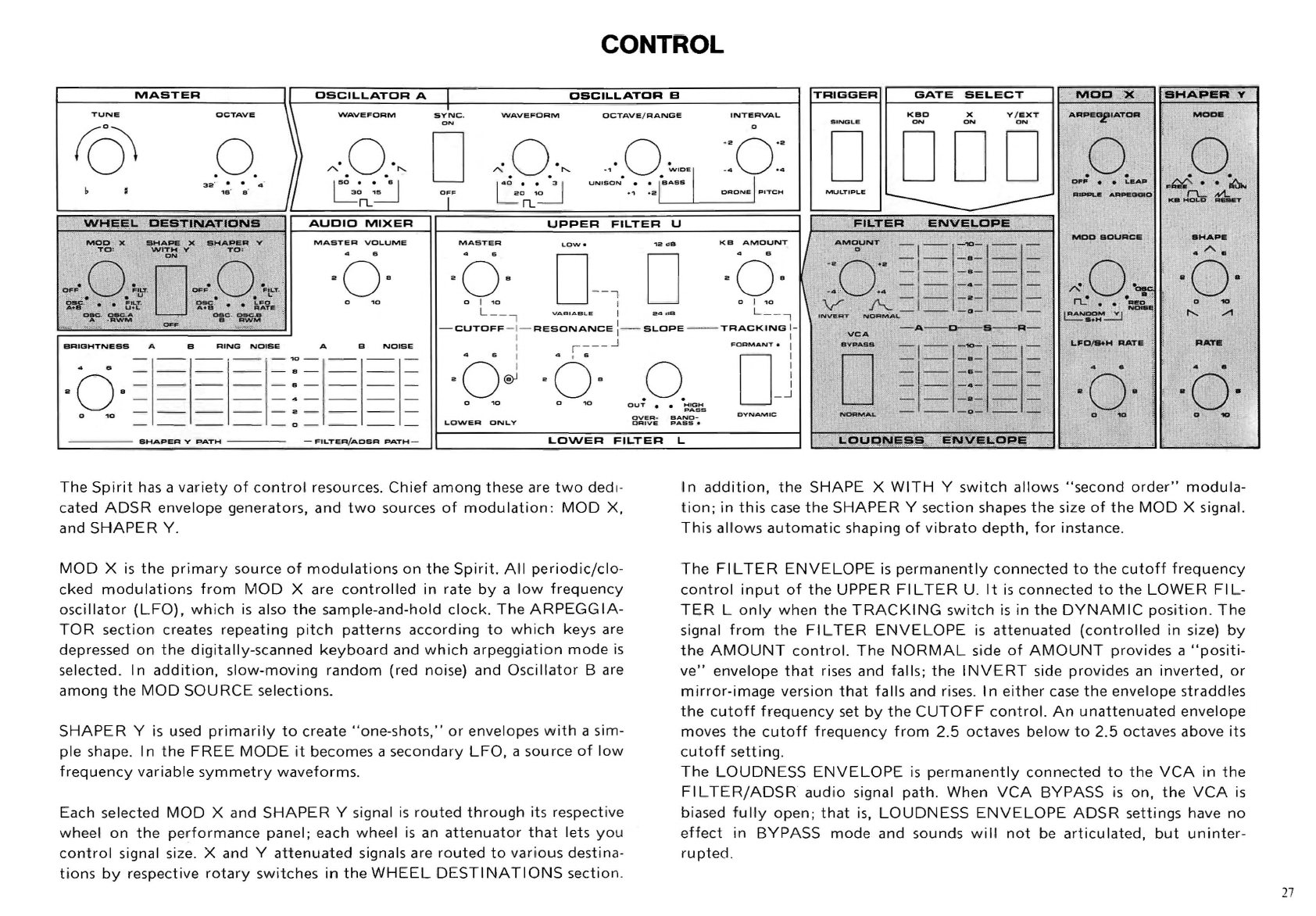
The
Spirit
has a
variety
of
control
resources.
Chief
among
these are
two
dedi·
cated
ADSR
envelope
generators,
and
two
sources
of
modulation:
MOD
X,
and
SHAPER
Y.
MOD
X
is
the
primary
source
of
modulations
on
the
Spirit.
All
periodic/clo-
cked
modulations
from
MOD
X are
controlled
in
rate
by
a
low
frequency
oscillator
(LFO),
which
is
also
the
sample-and-hold
clock.
The
ARPEGGIA-
TOR
section
creates
repeating
pitch
patterns
according
to
which
keys
are
depressed
on
the
digitally-scanned
keyboard
and
which
arpeggiation
mode
is
selected. In
addition,
slow-moving
random
(red noise) and
Oscillator
Bare
among
the
MOD
SOURCE
selections.
SHAPER
Y
is
used
primarily
to
create
"one-shots
,"
or
envelopes
with
a sim-
ple
shape. In
the
FREE
MODE
it
becomes a
secondary
LFO,
a
source
of
low
frequency
variable
symmetry
waveforms.
Each selected
MOD
X and
SHAPER
Y signal
is
routed
through
its respective
wheel
on
the
performance
panel;
each wheel
is
an
attenuator
that
lets
you
control
signal size. X and Y
attenuated
signals are
routed
to
various
destina-
tions
by
respective
rotary
switches
in
the
WHEEL
DESTINATIONS
section
.
In
addition,
the
SHAPE
X
WITH
Y
switch
allows
"second
order"
modula-
tion;
in
this
case
the
SHAPER
Y
section
shapes
the
size
of
the
MOD
X signal.
This
allows
automatic
shaping
of
vibrato
depth,
for
instance.
The
FI
L
TER
ENVELOPE
is
permanently
connected
to
the
cutoff
frequency
control
input
of
the
UPPER
FI L
TER
U. It
is
connected
to
the
LOWER
FI
L-
TER
L
only
when
the
TRACKI
NG
switch
is
in
the
DYNAM
IC
position
.
The
signal
from
the
FI
L
TER
ENVELOPE
is
attenuated
(controlled
in
size)
by
the
AMOUNT
control.
The
NORMAL
side
of
AMOUNT
provides
a
"positi-
ve"
envelope
that
rises and
falls;
the
INVERT
side
pro
vides an
inverted,
or
mirror-image
version
that
falls
and rises. In
either
case
the
envelope
straddles
the
cutoff
frequency
set
by
the
CUTOFF
control.
An
unattenuated
envelope
moves
the
cutoff
frequency
from
2.5
octaves
below
to
2.5
octaves
above
its
cutoff
setting.
The
LOUDNESS
ENVELOPE
is
permanently
connected
to
the
VCA
in
the
FI L
TER/AOSR
audio
signal
path.
When
VCA
BYPASS
is
on,
the
VCA
is
biased
fully
open;
that
is,
LOUDNESS
ENVELOPE
ADSR
settings have
no
effect
in
BYPASS
mode
and sounds
will
not
be
articulated,
but
uninter-
rupted
.
27
28
DESCRIPTION OF THE CONTROLS
TONE OSCILLATORS
MASTER
II
OSCILLATOR
A
OSCILLATOR
a
TUN.
DCTAV.
\
WAVtl.~OAM
aVNC.
WAV.FOAM
OCTAve
/
RANoa
INT.AVAL
rry
~
a
.0.
f}
",·.0.·"
D
A.O.·"
··0··
·0·
.,
. .
W'""I
-.
..
...
.. .
Ii
~'::J
L:'
.~
~ON.jPITC,",
~
I
~.
.
~
,. T
ao
10
VNI.ON
.:
:.1
......
.
n.
rL
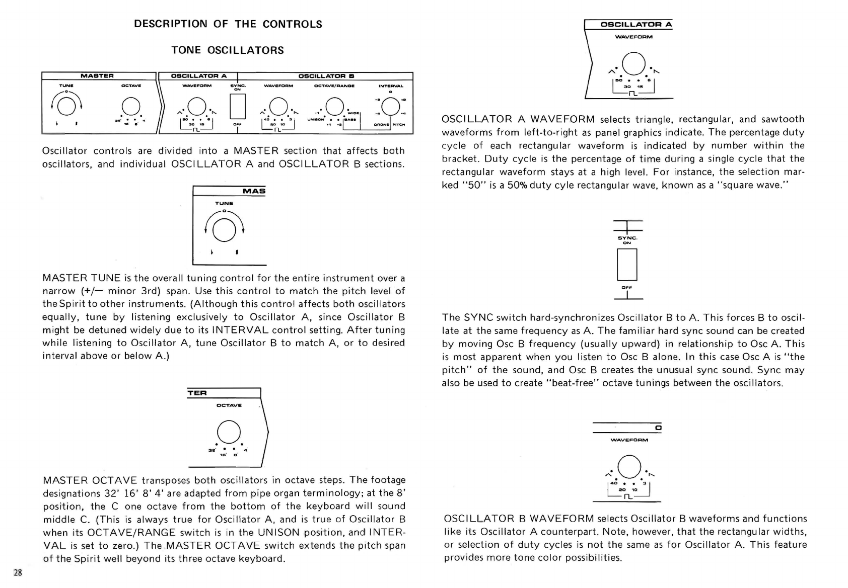
Oscillator
controls
are
divided
into
a
MASTER
section
that
affects
both
oscillators,
and
individual
OSCILLATOR
A
and
OSCILLATOR
B sections.
MAS
TUNE
MASTER
TUNE
is
the
overall
tuning
control
for
the
entire
instrument
over a
narrow
(+/-
minor
3rd)
span. Use
this
control
to
match
the
pitch
level
of
the
Spirit
to
other
instruments
.
(Although
this
control
affects
both
oscillators
equally,
tune
by
listening
exclusively
to
Oscillator
A,
since
Oscillator
B
might
be
detuned
widely
due
to
its
INTERVAL
control
setting.
After
tuning
while
listening
to
Oscillator
A,
tune
Oscillator
B
to
match
A,
or
to
desired
interval
above
or
below
A.)
TER
OCTAVE
.0.
MASTER
OCTAVE
transposes
both
oscillators
in
octave
steps.
The
footage
designations
32'
16'
8'
4'
are
adapted
from
pipe
organ
terminology;
at
the
8'
position,
the
C one
octave
from
the
bottom
of
the
keyboard
will
sound
middle
C.
(This
is
always
true
for
Oscillator
A,
and
is
true
of
Oscillator
B
when
its
OCTAVE/RANGE
switch
is
in
the
UN
ISON
position,
and
I
NTER-
VAL
is
set
to
zero.)
The
MASTER
OCTAVE
switch
extends
the
pitch
span
of
the
Spirit
well
beyond
its
three
octave
keyboard
.
OSCILLATOR
A
WAVEFORM
·0·
Ao
"-
. .
1150
_.
._
8 I
LO~
n..
OSCI
LLATOR
A
WAVEFORM
selects
triangle,
rectangular,
and
sawtooth
waveforms
from
left-to-right
as
panel graphics
indicate.
The
percentage
duty
cycle
of
each
rectangular
waveform
is
indicated
by
number
within
the
bracket.
Duty
cycle
is
the
percentage
of
time
during
a single
cycle
that
the
rectangular
waveform
stays
at
a
high
level.
For
instance,
the
selection
mar-
ked
"50"
is
a 50%
duty
cyle
rectangular
wave,
known
as
a
"square
wave."
SYNC.
D
OFF
~
The
SYNC
switch
hard-synchronizes
Oscillator
B
to
A.
This
forces
B
to
oscil-
late
at
the
same
frequency
as
A.
The
familiar
hard
sync
sound
can be created
by
moving
Osc B
frequency
(usually
upward)
in
relationship
to
Osc
A.
This
is
most
apparent
when
you
listen
to
Osc B alone. In
this
case
Osc A
is
"the
pitch"
of
the
sound, and Osc B creates
the
unusual
sync
sound.
Sync
may
also be used
to
create
"beat-free"
octave
tunings
between
the
oscillators.
c
WAVEFORM
·0·
A
"-
. .
140
_.
._
3 I
L01~
n..
OSCI
LlATOR
B
WAVEFORM
selects
Oscillator
B
waveforms
and
functions
like
its
Oscillator
A
counterpart.
Note,
however,
that
the
rectangular
widths,
or
selection
of
duty
cycles
is
not
the
same
as
for
Oscillator
A.
This
feature
provides
more
tone
color
possibilities.

'
SCILLATOR
B
OCTAVE
/
RANGE
·0·
0
'.
Clw,oe
UNISON
• •
BASS
.,
·a
OSCI
LLATOR
B
OCTAVE/RANGE
is
used
to
tune
Osc B
relative
to
Osc A.
The
first
four
switch
positions
provide
tuning
in
octave
steps. Osc B can be
tuned
to
the
sameoctave
(UNISON),
one
octave
lower
or
higher,
or
two
octaves
higher
than
Osc A.
The
BASS
and
WIDE
positions
cause
Oscillator
B
to
become
disconnected
from
all
manual
tuning
controls
other
than
the
INTERVAL
control.
That
is,
the
keyboard,
MASTER
TUNE,
MASTER
OCTAVE,
and
PITCH
BEND
wheel
now
have
no
influence
on Osc B
pitch.
(MOD
X,
SHAPER
Y,
and
the
rear panel OSC B
PEDAL
input
work
normally).
In
the
BASS
position,
the
I
NTERVAL
control
tunes
Osc B
from
30
to
300
Hz;
in
the
WI
DE
position,
from
2
to
10,000
Hz
.
BASS
and
WIDE
positions
make
it
possible
to
create
an Osc B
"drone,"
or
unvarying
pitch
that
sounds
as
you
play,
while
Osc A
follows
the
keyboard.
OSCIL.L.ATOR
B
OCTAVE
/
RANGE
INTERVAL
o
OSCILLATOR
B
INTERVAL
transposes Osc B
up
or
down
as
much
as
a
perfect
fifth
when
the
adjacent
OCTAVE/RANGE
is
in
one
of
the
first
four
"octave
step"
positions.
The
center
zero
position
causes
no
transposition;
slight
deviations
from
center
create
the
slight
mistuning
between
the
oscilla-
tors
that
adds
warmth
and fatness
to
the
sound.
As
discussed above,
the
I
NTERVAL
control
becomes a
continuous
tuning
control
for
Osc B
(only)
when
the
BASS
or
WI
DE
position
on
the
adjacent
OCTAVE/RANGE
control
is
selected. When
BASS
is
selected,
the
INTER-
VAL
Control
spans
four
octaves in
the
bass
(lower)
pitch
range.
When
WI
DE
is
selected,
the
I
NTERVAL
control
spans
the
12 octaves
of
Osc B range.
AUDIO
MIXER
AUOIO
MIXER
MASTER
VOL.UME
4 s
2
OB
0
10
BRIGHTN
•
••
A B
RING
NOISE
A B
NOISE
-
-1-
--
-
-10-
--
-I-
4 B -
--
--
--
-B
-
--
--
-
0 -
-1-
--
-B
-
--
--
-
Q B
-
--
--
--
-4 -
--
I
0
'0
-
--
--
--
-Q -
--
-
--
--
--
-
0-
--
SHAPER
V
PATH
FILTER/ADSR
PATH
Controls
in
this
section
let
you
combine
the
sound
sources available
to
both
audio
signal paths,
adjust
brightness in
the
SHAPER
Y
PATH,
and
adjust
overall
volume
of
both
paths.
BRIGHTNESS
adjusts
the
overtone
content
of
SHAPER
Y
PATH
signals.
This
control
changes
the
cutoff
frequency
of
a 6
dB
per
octave
lowpass
filter.
This
type
of
filter
is
similar
to
an
amplifier
tone
control
filter
.
The
SHAPER
Y
PATH
sliders
adjust
the
relative
strengths
of
oscillators
A
and B,
Ring
Modulator,
and Noise signals in
the
Shaper Y Path.
When
an
external
audio
signal
is
introduced
into
the
EXTERNAL
AUDIO
IN
jack
on
the
rear panel,
the
ex
ternal
signal takes
the
place
of
Noise
in
both
audio
signal and Noise
is
no
longer
available
as
an
audio
signal.
The
FI
L
TER/ADSR
PATH
sliders
adjust
the
relative
strengths
of
the
Tone
Oscillators
A and B, and Noise signals in
the
Filte
r/
ADSR
Path.
As
indicated
above,
the
EXTERNAL
AUDIO
IN
jack
on
the
rear panel
is
"normaled"
to
cause
any
external
signal
routed
the
re
to
appear in place
of
the
Noise
signal;
external
signal
strength
would
be
adjusted
using
the
NOISE
slider
in
this
case.
MASTER
VOLUME
adjusts
the
final
loudness levels
of
both
audio
channels.
This
is
an
attenuator;
for
best signal-to-noise
ratio
use high settings and
adjust
your
amplifier
accordingly
.
29
Table of contents
Other Crumar Synthesizer manuals


