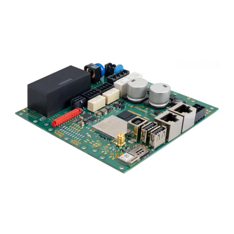
CruzPro SAR20 User guide

Warranty
CruzPro products are carefully tested and
adjustedatthefactorybeforeshippingand
are warranted for one full year against
original defects in materials or
workmanship. This warranty does not
include damage to the product resulting
from accident, misuse or neglect.
If the product should become defective
within the warranty period, we will repair
or replace it free of charge, including free
return transportation, provided it is
deliveredprepaidtothedealerfromwhom
it is originally purchased.
This warranty gives you specific legal
rights, and you may also have other rights
which vary from state to state, or country
to country.
Page 14 Page 3
Table of Contents
Summary and Warnings . . . . . . . . . . . . . . . . . . . 2
Introduction . . . . . . . . . . . . . . . . . . . . . . . . . . 4
Specifications . . . . . . . . . . . . . . . . . . . . . . . . . 7
Installation . . . . . . . . . . . . . . . . . . . . . . . . . . . . 8
Programming the Jumpers . . . . . . . . . . . . . . . . 13
Warranty . . . . . . . . . . . . . . . . . . . . . . . . . . . . . . 16
Programming Alternator Size
0-46 47-61 62-81 82-108
Amps Amps Amps Amps
109-144 145-192 193-257 258-344
Amps Amps Amps Amps
Programming Battery Size
0-99 100-144 145-210 211-306
A-H A-H A-H A-H
307-446 447-651 652-950 951-1387
A-H A-H A-H A-H
Handbook
O
w
n
e
r'
s

Page 4
Introduction
The SAR-20 Smart Alternator Regulator
commands maximum safe output from your 12 or
24VDCalternatorwhilemonitoringbatteryvoltage
and temperature. The bulk of the battery charge is
delivered at maximum alternator output allowing
batteryvoltagetoriseuntilthe"absorptionvoltage"
has been reached. The SAR-20 then lowers the
alternator output to maintain a constant battery
voltage at the absorption point. The absorption
voltageismaintainedforaperiodoftimedependent
upon several factors and then the SAR-20 cuts
back the battery voltage to a safe "float" voltage.
TheSAR-20willalsoenableyoutodesulfateyour
battery plates by enabling an "equalization cycle"
(In float mode, press front panel switch for 15
seconds).During equalizationthe SAR-20slowly
raisesbatteryvoltagetoanequalizationlevelwhile
limiting the charge current to about 4-6% of your
battery'samp-hour capacity.This safelydissolves
the sulfates that form on the battery plates during
discharge and extends battery life. The SAR-20
will stay in the equalization stage until the
Programming the Jumpers
Your Smart Alternator Regulator (SAR) is pro-
vided with nine black programming jumpers.
These jumpers are placed on the programming
pins (shown below, Figure 2, and Page 14) as
needed. ThejumperstelltheSARbatteryvoltage,
alternatorsize,batterybankcapacity,batterychem-
istry and if your alternator is "hot" rated.
Ifyourbatteryisawetcelltype,placeajumperon
the "Wet/Gel" location. If your alternator can
deliver maximum output continuously without
burningup,placeajumperonthe"HotRated/No"
location. Remove the jumper on the 12/24V line
ifyouare usingtheSAR-20 witha24V alternator
or keep the jumper in place if using 12V.
Placejumpersasshownonpage14toprogramthe
sizeof youralternator andthe sizeof yourbattery
bank. 12 VDC
Operation 24 VDC
Operation
Page 15
Page 13
SARMAN-O 1999 BV Engineering
http://www.cruzpro.com
e-mail: [email protected]
Other CruzPro Products
lDepthsounder & Depthsounder /w Water Temperature
lSpeed/Log/w Water Temperature Display
lDC Volts/Amps/Amp-Hour Monitors
lAC Volts/Amps/Frequency/kW Monitor
lLPG/Petrol Gas Detectors/Alarms
lBilge Water Detector/Alarms & Pump Controllers
lWindlass Controller/Chain Counter
lDigital Fuel Gauge/Consumption Calculator
lSmart and Manual Alternator Regulators
lMarine Security System
lRPM/Engine Hours/Elapsed Time Gauge
lDigital Oil Pressure Gauge/Alarm
lDigital Water Temperature Gauge/Alarm
lDigital Amps Gauge
l3 Bank Digital Volts Gauge/Alarm
lDigital Clock/Watch/Race Timers/Alarms
l8 and 16 Amp Light Dimmers
lBattery Voltage Monitors/Alarms
lSolar Panel Charge Controllers
l4 & 8 Channel NMEA Combiners/RS-232 Convertors
lEngine/Exhaust Temperature Monitor/Alarm
lNMEA 0183 Remote Data Repeater/w 4 Input Channels
Full details at http://www.cruzpro.com
SUMMARY & WARNINGS
Indicator LED:
l
1blink per 2 seconds -Bulk deliverystage
l
2 blinks per 2 seconds - Absorption stage
l
3 blinks per 2 seconds - Float stage
l
Continuous blinking - Equalization stage
l
No blinking - Loss of input voltage or loss
ofbatteryvoltagesenseline(automaticshut-
down within 30 seconds typical, one minute
maximum).
To energize an Equalization cycle: When
theSAR20 indicatorLED blinks3 timesper
2 seconds (float mode) you can start an
equalization cycle (see page 4) by holding
down the front panel button for 15 seconds.
Be sure to disconnect anything that can't
handle equalization level voltages (up to
16.5 VDC or 33 VDC). If you connect or
disconnectanyloadsfromthebatterywhile
in equalization mode, the equalization
current will not be correct - don't do it.

Page 5
Page 10
Page 12
Specifications
Input Voltage: 9.5 to 35 VDC (external battery
voltage sensing).
Operatingtemperature:0 to50 degCelsius (32
to 122 deg Fahrenheit).
Size: 100 x 60 x 30 mm (4 x 2.4 x 1.2 inch).
Drive Current: 8 Amps maximum (Automatic
cut-back for non-hot rated alternators). Ramps
current up from 0% to 100% in 30 seconds to
prevent belt slip after waiting 60 seconds for
engine to warm up.
Steps: Bulk, Absorption, Float and Equalization.
Temperature compensated with included probe.
Indicator LED:
l
1 blink per 2 seconds - Bulk delivery stage
l
2 blinks per 2 seconds - Absorption stage
l
3 blinks per 2 seconds - Float stage
l
Continuous blinking - Equalization stage
l
No blinking - Loss of input voltage or loss of
battery voltage sense line (automatic shut-down
within30secondstypical,oneminutemaximum).
Page 7
equalizationvoltage has beenreached, 4hours, or
manually by pressing the front panel button for
four seconds, whichever occurs first.
The correct absorption, float and equalization
voltages are dependent upon temperature and
battery chemistry. The higher the temperature the
lower values of absorption, float and equalization
voltagesthatmustbeusedtooptimizebatterylife.
For this reason a remote sensor is used to monitor
battery temperature and adjust the voltages
accordingly. The SAR-20 also has some
programmingjumpersinsideto tellitwhattypeof
batteryyouareusingandfurtheradjustthecharging
voltages accordingly.
During the bulk delivery phase the SAR-20 will
commandthealternatortodelivermaximumoutput
continuouslyuntiltheabsorptionvoltageisreached.
While many modern alternators can do so, some
alternatorsarenot"hotrated"todeliverfulloutput
continuously and can be damaged by excessive
heat. For this reason the SAR-20 can be told
whetheryouralternator ishotrated ornotandwill
automatically cut back the output of a non hot-
Figure 2 - SAR-20 Connections
and Jumper Locations
Now check your wiring carefully. After you are
sure there are no errors in the wiring, program the
jumpers as described on page 13 and 14.
Turn on the ignition switch to apply power to the
SAR-20 At this point the front panel LED should
flashone timeeverytwo seconds. Ifnot,re-check
your wiring. If all is working properly, install the
front cover.
Note: Afterallowingtheenginetowarm upfor 60
seconds, theSARslowlyrampsupthecurrentover
the next 20-30 seconds so as to minimize belt
slippage.
Important - Connect Black
temp. sense wire to Terminal B

Page 11
Page 6
Page 9
Page 8
rated alternator to 80% of maximum after 15
minutes.
With the heavy loads being demanded by the
electrical and electronic conveniences found on
many boats it's becoming more common for a
second alternator to be fitted to the engine. Most
alternators require about 3-4 amps excitation to
their field winding in order to deliver maximum
output so the SAR-20 is designed to deliver 8
amps, driving up to two alternators.
Anotherhandy featureofthe SAR-20 isatrouble-
shooting LED that tells you what it's doing. The
LED blinks in these various combinations:
l
1 blink per 2 seconds - Bulk delivery stage
l
2 blinks per 2 seconds - Absorption stage
l
3 blinks per 2 seconds - Float stage
l
Continuous blinking - Equalization stage
l
No blinking - Loss of input voltage or loss of
battery voltage sense line (checked once every 60
seconds).
Installation
Before starting the installation, please read this
entire section. The instrument is NOT water-
proof and must be located in an area that will not
getwet. Use18gauge(1mmdiameter)wiretothe
screw terminals for the + Battery Sense and -
BatterySense. Use 16 gaugeor largerwire forall
other connections.
Removethecasefrontandalignthecasebackonto
anysuitablesurface. Using thecasebackasadrill
guide, mark the location of the holes with a soft
pencillead. Removethecasebackand drill 3mm
(1/8 inch) holes where indicated. Mount the case
back using stainless steel screws.
Refer to Figures 1 and 2:
a) Connect the temperature sensor wires to termi-
nals(B)and(C)usingasmallflatscrewdriver. The
black wire to terminal B. Bolt the sensor to the
negativebatterypostofthebatterytobemonitored
(charged).
Figure 1 - SAR-20 Wiring
b) Connect the power ground terminal to the
battery negative distribution post.
c) Connect the positive sense line (D) directly to
the battery positive terminal through a 5 amp fuse
located near the battery.
d) Connect the positive power terminal to the
ignition switch through a 5 amp fuse.
e) Connect the alternator ground terminal to the
alternator negative post.
f) ConnecttheFieldterminaltothealternatorfield
winding.
Note: Terminal (A) and the single extra jumper
near the top right are reserved for future use.
Note: Temperature sensor lug to
battery NEGATIVE terminal.
Other CruzPro Controllers manuals
