Truma SecuMotion Operating instructions

Gebrauchsanweisung Seite 2
Einbauanweisung Seite 6
Im Fahrzeug mitzuführen!
Operating instructions Page 11
Installation instructions Page 15
To be kept in the vehicle!
Mode d‘emploi Page 20
Instructions de montage Page 25
À garder dans le véhicule !
Istruzioni per l‘uso Pagina 30
Istruzioni di montaggio Pagina 35
Da tenere nel veicolo!
SecuMotion
Page 72
Gebruiksaanwijzing Pagina 40
Inbouwhandleiding Pagina 44
Im vertuig meenemen!
Brugsanvisning Side 49
Monteringsanvisning Side 53
Skal medbringes i køretøjet!
Instrucciones de uso Página 58
Instrucciones de montaje Página 63
¡Llévalas en el vehículo!

2
Verwendungszweck
SecuMotion ist eine Sicher-
heits-Gasdruck-Regelanlage für
Caravans und Motorcaravans.
Die Gasdruck-Regelanlage ge-
währleistet einen gleichmäßigen
Ausgangsdruck von 30 mbar bei
einem zulässigen Eingangsdruck
von 0,3 – 16 bar.
Für den Anschluss der Gasfla-
sche an die Gasdruck-Regelan-
lage ist ein Hochdruck-Schlauch
mit Schlauchbruchsicherung
(SBS) zwingend erforderlich. Die
hierfür notwendigen Hochdruck-
Schläuche bietet Truma in den
gängigsten Anschlussvarianten
für europäische Gasflaschen an
(siehe Seite 68 – 69).
SecuMotion regelt und über-
wacht den Verbrauch des
Flüssiggases. Wird der Nenn-
verbrauch überschritten oder
sinkt der Druck am Ausgang
der Gasdruck-Regelanlage un-
ter 27 mbar (z. B. durch einen
Gasrohrbruch), schaltet der inte-
grierte Gas-Strömungs-Wächter
(GSW) den Gasfluss ab.
Die Verwendung der Gasdruck-
Regelanlage in geschlossenen
Räumen (Haushalt, Mobilhei-
men) auf Seewasserbooten oder
in EX-Zone 0 (z. B. Tankwagen)
ist nicht zulässig.
Die integrierte Überdrucksi-
cherung entspricht den Anfor-
derungen als Sicherheitsein-
richtung für den gewerblichen
Bereich gegen unzulässig hohen
Druckanstieg (z. B. in Deutsch-
land nach BGV D 34).
Die Druckregelgeräte
und Schlauchleitungen
müssen spätestens 10 Jahre
(bei gewerblicher Nutzung
8 Jahre) nach Herstellungsda-
tum gegen neue ausgewechselt
werden. Der Betreiber ist dafür
verantwortlich.
Hinweise zum Betrieb der
Gasanlage während der Fahrt.
Bei Motorcaravans ab Baujahr
01/2007 muss gemäß der Heiz-
geräterichtlinie 2001/56/EG mit
den Ergänzungen 2004/78/EG
und 2006/119/EG für den Betrieb
einer Flüssiggasheizung wäh-
rend der Fahrt, eine Sicherheits-
Absperreinrichtung vorgesehen
SecuMotion
3
werden, welche bei einem Lei-
tungsabriss durch einen Unfall
verhindert, dass ungewollt Gas
austreten kann.
Truma SecuMotion, mit ent-
sprechend ausgelegter Gasins-
tallation, erfüllt in Verbindung
mit Hochdruck-Gasschläu-
chen mit integrierter Schlauch-
bruchsicherung (SBS) alle
relevanten Normen, Vorschriften
und Richtlinien und erlaubt so-
mit den europaweiten Betrieb
der Gasanlage, auch während
der Fahrt.
Für das Heizen während der
Fahrt in Caravans empfehlen
wir zur Sicherheit ebenfalls eine
Sicherheitseinrichtung.
Für Fahrzeuge vor Baujahr
01/2007 gibt es keine Einschrän-
kungen für den Betrieb der Gas-
anlage während der Fahrt.*
* Ausnahme für Frankreich:
In Frankreich ist der Betrieb der
Gasanlage während der Fahrt,
nur in Typgeprüften Fahrzeu-
gen mit Erstzulassung ab dem
01.01.2007 erlaubt. Bei älteren
Fahrzeugen ist der Betrieb der
Gasanlage während der Fahrt
auch in Verbindung mit einer
Sicherheits-Absperreinrichtung
nicht zulässig.
Gasflaschen welche nicht an die
Gasinstallation angeschlossen
sind, müssen stets geschlossen
und mit Schutzkappen versehen
werden. Angeschlossene Gasfla-
schen gelten als Betriebsmittel
und nicht als Gefahrgut (ADR
Freistellung gemäß Abschnitte
1.1.3.1 und 1.1.3.2. e).

4
Gebrauchsanweisung
Für den Betrieb der Gasdruck-
Regelanlage SecuMotion, ist
die Verwendung von stehenden
Gasflaschen aus denen Gas aus
der Gasphase entnommen
wird zwingend vorgeschrieben.
Gasflaschen aus denen Gas aus
der Flüssigphase entnommen
wird (z. B. für Stapler) sind für
den Betrieb verboten, da sie zur
Beschädigung der Gasanlage
führen.
Inbetriebnahme
Gegebenenfalls Gasfernschalter
öffnen.
1.
2.
3.
4.
3 sec
1. Flaschenventil öffnen.
2. Schlauchbruchsicherung
(grüne Taste) am Hochdruck-
Schlauch kräftig drücken.
3. GSW-Rückstellknopf (grüne
Taste) an der Gasdruck-Regelan-
lage langsam drücken.
4. GSW-Rückstellknopf (grüne
Taste) an der Gasdruck-Regelan-
lage langsam (3 Sek.) loslassen.
Ist bei nochmaligem Drücken kein
Druckpunkt spürbar, ist die Gas-
druck-Regelanlage betriebsbereit
(falls erforderlich, den Vorgang
wiederholen).
Gegebenenfalls Gasgeräte in
Betrieb nehmen.
Bei längerem Nichtgebrauch und
geschlossenen Gasflaschen kann
SecuMotion abschalten.
Gasflaschenwechsel
Zum An- und Abschrauben der
Hochdruck-Schläuche bitte
die beiliegende Schraubhilfe
verwenden. Sie gewährleistet

5
das nötige Anzugsmoment und
verhindert Beschädigungen
an der Verschraubung durch
falsches Werkzeug.
Gasrest: Nicht rauchen,
keine offenen Flammen!
– Ventil der leeren Gasflasche
schließen.
– Hochdruck-Schlauch von der
Gasflasche abschrauben bzw.
falls vorhanden, Aufsteck-
adapter abnehmen.
– Hochdruck-Schlauch an die
volle Gasflasche anschrauben
bzw. falls vorhanden, Auf-
steckadapter aufstecken.
– Ventil der vollen Gasflasche
öffnen.
– Schlauchbruchsicherung
und GSW drücken (siehe
„Inbetriebnahme“).
Schlauchanschluss am
Flaschenventil nach jedem
Eingriff auf Dichtigkeit überprü-
fen (siehe „Dichtigkeitsprüfung
des Hochdruckbereichs“).
Schlauchwechsel
Zum An- und Abschrauben der
Hochdruck-Schläuche bitte die
beiliegende Schraubhilfe ver-
wenden. Sie gewährleistet das
nötige Anzugsmoment und ver-
hindert Beschädigungen an der
Verschraubung durch falsches
Werkzeug.
Gasrest: Nicht rauchen,
keine offenen Flammen!
– Gasflaschenventil schließen.
– Hochdruck-Schlauch von der
Gasflasche (bzw. vom
Aufsteckadapter) und vom
Eingang der Gasdruck-Regel-
anlage abschrauben.
Beim Schlauchwechsel
sicherstellen, dass die
dem Schlauch beiliegende
Dichtung (Schlauchausgang –
Eingang Gasdruck-Regelanlage)
ordnungsgemäß installiert und
nicht beschädigt ist.
Wir empfehlen, die
Dichtung (Art.-Nr.
50020-76300) bei jedem
Schlauchwechsel zu erneuern.
– Länderspezifischen Hoch-
druck-Schlauch am Eingang
SecuMotion und an die
Flasche (bzw. am Aufsteck-
adapter) anschrauben.
– Gasflaschenventil öffnen.
– Schlauchbruchsicherung und
gegebenenfalls GSW drücken
(siehe „Inbetriebnahme“).
Den Schlauchanschluss am
Flaschenventil und am Eingang

6
der Gasdruck-Regelanlage
SecuMotion nach jedem Ein-
griff auf Dichtigkeit überprüfen
(siehe „Dichtigkeitsprüfung des
Hochdruckbereichs“).
Dichtigkeitsprüfung des
Hochdruckbereichs
Die Dichtigkeitsprüfung
des Niederdruckbereichs
muss vom Fachmann durchge-
führt werden. Darüber hinaus
empfehlen wir eine Überprüfung
der Dichtigkeit des Hochdruck-
bereichs durch den Betreiber der
Gasanlage bei jedem Flaschen-
oder Schlauchwechsel.
Insbesondere die Verschraubungen
am Gasflaschenventil und am Ein-
gang der Gasdruck-Regelanlage
sollten mit geeigneten Mitteln – bei-
spielsweise mit einem Lecksuch-
spray nach DIN EN 14291 – auf
Dichtigkeit überprüft werden.
Einbauanweisung
Montage nur vom Fachmann!
Einbauanweisung vor dem
Einbau unbedingt lesen und
befolgen!
Die Gebrauchsanweisung ist
dem Betreiber auszuhändigen!
Erstinstallation
Hinweis für Fahrzeughersteller:
Zur korrekten Auslegung bzw.
Berechnung der Gasrohre stellt
Truma ein Computer-Programm
(LPG-Flow) zur Verfügung.
SecuMotion wird eingangsseitig
über das Außengewinde
M20 x 1,5 (G.13) und ausgangs-
seitig über eine Schneidringver-
schraubung (8 mm oder 10 mm)
angeschlossen.
Der Ausgangsnenndruck von
30 mbar muss mit dem Betriebs-
druck aller im Fahrzeug einge-
bauten Geräte übereinstimmen.
Austausch der
Gasdruck-Regelanlage
Eine vorhandene SecuMotion
muss stets durch eine
SecuMotion mit gleichen Kenn-
werten ersetzt werden. Die
Gasinstallation darf dabei nicht
verändert werden, z. B. durch
Nachrüsten eines zusätzlichen
Heizgerätes.
Veränderungen an der
Gasanlage
Sollte eine Nachrüstung eines
Gasverbrauchers oder ein sons-
tiger Umbau der Gasinstallation
erforderlich sein, dann muss
die Funktionstüchtigkeit der

7
SecuMotion unbedingt weiter
gewährleistet sein (siehe
„Funktionsprüfung GSW“).
Einbau und Anschluss der
Gasdruck-Regelanlage
Die Gasdruck-Regelanlage muss
so montiert werden, dass sich
der Eingang der Gasdruck-
Regelanlage mindestens auf
Höhe des Flaschenventils
befindet.
Die Montage oberhalb
des Flaschenventils er-
schwert das Eindringen von Gas
in Flüssigphase in den Nieder-
druckbereich, vor allem während
der Fahrt. Die Verwendung von
Gasrohren Ø 10 mm verbessert
die Funktionseigenschaften aller
angeschlossenen Geräte. Die
Gasdruck-Regelanlage bei Ver-
wendung im Freien beispielswei-
se durch die Verwendung einer
Schutzhaube gegen Witterungs-
einflüsse schützen.
– Hochdruck-Schlauch (nur
mit SBS!) an den Eingang
der Gasdruck-Regelanlage
anschrauben, evtl. Winkelver-
schraubung (a) verwenden
(siehe „Zubehör“).
a
– Geeignete Position für die Gas-
druck-Regelanlage auswählen,
insbesondere: Typenschild
lesbar, GSW-Knopf erkennbar
und gut erreichbar, Beschädi-
gungen beim Flaschenwech-
sel vermeiden, Eindringen von
Gas in Flüssigphase erschwe-
ren, Platz für die Nachrüstung
von DuoComfort einplanen,
Hochdruck-Schlauch span-
nungsfrei verlegen.
95 mm
130 mm
– Gasdruck-Regelanlage mit
2 Schrauben an der Wand
befestigen.

8
– Das Gaszuleitungsrohr Ø 8 mm
oder 10 mm gemäß der gül-
tigen Installationsvorschriften
für Schneidringverschrau-
bungen am Ausgang der Gas-
druck-Regelanlage anschlie-
ßen. Beim Festziehen sorgfältig
mit einem zweiten Schlüssel
an den dafür vorgesehenen
Schlüsselflächen gegenhalten.
– Nach erfolgtem Einbau der
Gasdruck-Regelanlage die
Gasanlage auf Dichtigkeit
überprüfen (siehe „Dichtig-
keitsprüfung des Niederdruck-
bereichs“) sowie gegebenen-
falls die Funktion des GSW
überprüfen (siehe „Funktions-
prüfung des GSW“).
– Schlauchanschluss am Ein-
gang der Gasdruck-Regelan-
lage SecuMotion (z. B. mit
einem Lecksuchspray nach
DIN EN 14291) auf Dichtigkeit
überprüfen.
Dichtigkeitsprüfung des
Niederdruckbereichs
Prüfung nur vom
Fachmann!
– Alle Verbraucher abstellen.
– Absperrventile und gegebe-
nenfalls Gasfernschalter
öffnen.
– Schraubkappe des Prüfan-
schlusses (b) abschrauben
und Prüfpumpe mit Prüf-
schlauch an den Prüfan-
schluss anschließen.
– Schutzkappe des Prüfventils (c)
abnehmen und das Ventil mit
einen Gabelschlüssel (Schlüs-
selweite 6 mm) um 90° im
Uhrzeigersinn drehen.
bc
– Dichtigkeitsprüfung durchfüh-
ren (z. B. in Deutschland nach
G 607).
– Bei undichter Gasanlage Gas-
flaschenventil schließen, die
Gasanlage umgehend in Ord-
nung bringen und das Gasfla-
schenventil zwischenzeitlich
nicht mehr öffnen.
– Nach erfolgreicher Prüfung
das Prüfventil unbedingt um
90° gegen den Uhrzeigersinn
bis zum Anschlag zurück-
drehen und Schutzkappe
aufstecken.

9
– Schraubkappe wieder auf das
Prüfventil aufschrauben.
Funktionsprüfung
des GSW
Die Funktion des GSW hängt un-
mittelbar mit den Eigenschaften
der Gasrohrinstallation zusam-
men und muss daher unbedingt
für jeden Fahrzeugtyp exemp-
larisch überprüft werden. Diese
Prüfung ist damit fester Bestand-
teil der Auslegungsprozedur! Wir
empfehlen darüber hinaus eine
Serien begleitende Funktionsprü-
fung, um negativen Einflüssen
eventueller Änderungen der
Installationspraxis entgegen zu
wirken.
– Alle Absperrventile öffnen.
– Erstes Heizgerät von der Lei-
tung abschrauben und die Lei-
tung provisorisch verschließen.
– Gasanlage in Betrieb nehmen
(siehe „Gebrauchsanweisung“).
– Provisorischen Verschluss
öffnen. Es darf nur kurzzeitig
Gas ausströmen, bis der GSW
anspricht.
– Heizgerät mit der Gasleitung
verschrauben.
– Bei mehr als einem Heizgerät
muss die Prüfung für alle
Geräte separat durchführt
werden!
– Dichtigkeitsprüfung
durchführen (siehe „Dich-
tigkeitsprüfung des
Niederdruckbereichs“).
Zubehör
Hochdruck-Schläuche
(mit Schlauchbruchsicherung)
siehe Seite 68 – 69
Anschlussschlauch 1,5 m
zum Anschluss externer
Gasflaschen
– Anschluss G.5 für Deutschland –
(Art.-Nr. 50020-61300)
Ersatzdichtung
für Hochdruckanschluss
M20 x 1,5 (G.13);
(Art.-Nr. 50020-76300)
DuoComfort
Umschaltventil für die
Zweiflaschenanlage
(Art.-Nr. 51500-01)
EisEx, Reglerbeheizung
(Art.-Nr. 53101-01)
Winkelverschraubung 90°
(Art.-Nr. 50020-56000)

10
Gasfernschalter
zum Absperren der Gasversor-
gung aus dem Innenraum des
Fahrzeugs
GS 8 (Art.-Nr. 57013-01)
GS 10 (Art.-Nr. 57023-01)
Prüfschlauch
(Art.-Nr. 50020-61200)
Technische Daten
ermittelt nach EN 12864
bzw. Truma Prüfbedingungen
Gasart
Flüssiggas (Propan / Butan)
Eingangsdruck p1
0,3 – 16 bar
Ausgangsdruck p2
30 mbar
Durchflussmenge Qn
siehe Aufdruck an der
Gasdruck-Regelanlage
Abschaltpunkt des GSW
27 mbar bzw. 125 % Qn
Eingang Gasdruck-Regelanlage
Außengewinde M20 x 1,5 (G.13)
Ausgang Gasdruck-Regelanlage
Schneidringverschraubung
8 mm / 10 mm
Empfohlenes Anzugsmoment
3 – 5 Nm für Überwurfmutter
M20 x 1,5 (G.13)
Konformitätserklärung
Die Truma Gasdruck-Regelan-
lage SecuMotion entspricht der
Druckgeräte-Richtlinie 97/23/EG
unter Anwendung der EN 12864/D
und der Richtlinie 2004/78/EG
Anhang VIII „Sicherheitsanfor-
derungen an LPG-betriebene
Verbrennungsheizgeräte“.
Produkt-Ident-Nummer
CE-0085BQ0102
DG approval number 3894
Technische Änderungen
vorbehalten!

11
Intended use
SecuMotion is a safety gas pres-
sure regulation system for cara-
vans and motor homes. The gas
pressure regulation system pro-
vides an even output pressure of
30 mbar, with a permissible ad-
mission pressure of 0.3 – 16 bar.
A high-pressure hose with hose
rupture protection (SBS) is es-
sential for connecting the gas
cylinder to the gas pressure reg-
ulation system. Truma provides
the necessary high-pressure
hoses with the most commonly-
used connection variants for
European gas cylinders (see
pages 68 – 69).
SecuMotion regulates and moni-
tors the consumption of liquid
gas. If the specified consump-
tion is exceeded or if the pres-
sure at the regulator outlet falls
below 27 mbar (due to a gas
pipe break, for example), the
integrated gas flow monitor will
shut off the flow of gas.
The use of the gas pressure reg-
ulation system is not permitted
in confined spaces (households,
caravan holiday homes), on sea-
going boats or in explosion pro-
tection zone 0 (e.g. tank trucks).
The integrated overpressure
safety device complies with the
requirements for a commercial
safety device against excessively
high pressure increases (for ex-
ample, in Germany according to
BGV D 34).
The pressure regulating
devices and hoses must
be replaced with new ones no
more than 10 years after their
date of manufacture (every
8 years if used commercially).
This is the responsibility of the
operator.
Notes on using the gas
system while driving:
With motor homes as of con-
struction year 01/2007, in
accordance with the heating
equipment directive 2001/56/EC
with annexes 2004/78/EC and
2006/119/EC, a safety shut-off
device must be provided for the
operation of a liquid gas heater
while driving that prevents gas
from inadvertently escaping if
a line breaks in the event of an
SecuMotion

12
accident must be provided for
operating while driving.
With an appropriately designed
gas installation and in conjunc-
tion with high-pressure gas
hoses with integrated hose
rupture protection (SBS), Truma
SecuMotion complies with
all of the relevant standards,
regulations and directives, and
therefore allows the gas sys-
tem to be used while driving
throughout Europe.
We also recommend the use of
a safety device for heating while
driving in caravans.
For vehicles manufactured
before 01/2007 there are no
restrictions for operating the gas
system while driving.*
* Exception for France:
In France the operation of the
gas system while driving is only
permitted in type-tested vehi-
cles with initial registration as
of 01.01.2007. In older vehicles
the operation of the gas system
while driving is non-permissi-
ble, even in combination with a
safety shut-off device.
Gas cylinders that are not con-
nected to the gas installation
must be closed at all times
and provided with protective
caps. Connected gas cylinders
are considered to be operating
materials and not hazardous
materials (ADR exemption in ac-
cordance with sections 1.1.3.1
and 1.1.3.2 e).
Operating instructions
The use of upright gas cylinders
from which gas is taken in the
gas phase is mandatory for the
operation of the SecuMotion
gas pressure regulation system.
Gas cylinders from which gas
is taken in the liquid phase (e.g.
for fork lifts) must not be used,
since they would result in dam-
age to the gas system.

13
Taking into operation
Open gas remote switch if
present.
1.
2.
3.
4.
3 sec
1. Open the cylinder’s valve.
2. Firmly press the hose rupture
protection device (green button)
on the high pressure hose.
3. Press gas flow monitor reset
button (green button) on gas
pressure regulation system
slowly.
4. Release gas flow monitor
reset button (green button) on
gas pressure regulation system
slowly (3 seconds).
If no pressure point is felt when
the button is pressed again, the
gas pressure regulation system
is ready for operation (repeat
procedure if necessary).
Start the gas-burning devices if
desired.
If the gas cylinders are closed,
SecuMotion may switch off after
an extended period of no usage.
Changing a gas cylinder
Please use the included screwing
tool to attach and remove the high
pressure hoses. It will help you
generate the necessary tightening
torque and will prevent damage
to the screw fittings, which may
otherwise result from using an
improper tool.
Residual gas: No smoking!
No open flames!
– Close the empty gas cylinder's
valve.
– Unscrew the high pressure
hose from the gas cylinder
and remove the clip-on adapt-
er, if present.
– Screw the high pressure hose
to the full gas cylinder and apply
the clip-on adapter, if present.
– Open the full cylinder’s valve.

14
– Press the hose rupture protec-
tion device and the gas-flow
monitor (see “Taking into
operation”).
Anytime after making
changes, check the hose
connection to the cylinder valve
for leaks (see “Checking for
leaks in the high pressure area”).
Exchanging hoses
Please use the included screw-
ing tool to attach and remove
the high pressure hoses. It will
help you generate the neces-
sary tightening torque and will
prevent damage to the screw
fittings, which may otherwise re-
sult from using an improper tool.
Residual gas: No smok-
ing! No open flames!
– Close the gas cylinder’s valve.
– Unscrew the high pressure
hose from the gas cylinder (or
from the clip-on adapter) and
from the gas pressure regula-
tion system inlet.
When performing a
hose change, please
ensure that the gasket pro-
vided with the hose (hose
outlet – gas pressure regula-
tion system inlet) is correctly
installed and undamaged.
We recommend that the
gasket (part no. 50020-
76300) be replaced with every
hose change.
– Screw country-specific high-
pressure hose to SecuMotion
inlet and cylinder (or to clip-on
adapter).
– Open the gas cylinder’s valve.
– Press the hose rupture protec-
tion device and, if necessary,
the gas-flow monitor (see
“Taking into operation”).
Anytime after making changes,
check the hose connections to
the cylinder valve and to the inlet
of the SecuMotion gas pressure
regulation system for leaks (see
“Checking for leaks in the high
pressure area”).
Checking for leaks in the
high pressure area
A trained technician must
check the low pressure
area for leaks. In addition, we
recommend that the person re-
sponsible for operating the gas
system check the high pressure
area for leaks after every cylinder
or hose replacement.

15
In particular, the screw fittings
on the gas cylinder valve and on
the gas pressure regulation sys-
tem inlet should be checked for
leaks with the proper tools, such
as a leak-finder spray according
to DIN EN 14291.
Installation instructions
Assembly by a technician only!
Always read and follow the in-
stallation instructions!
Always give the operating in-
structions to the operator!
First installation
Notice for vehicle manufacturers:
Truma provides a computer
program called LPG Flow, which
facilitates proper configuration
and calculation of the gas pipes.
A male thread M20 x 1.5 (G.13)
facilitates inlet-side connection
of SecuMotion; a cutting-ring
screw fitting (8 or 10 mm) is
used at the outlet side.
The nominal outlet pressure of
30 mbar must match the
operational pressure of all de-
vices installed in the vehicle.
Replacing the gas pressure
regulation system
An existing SecuMotion must
always be replaced with a
SecuMotion with the same
specifications. The gas installa-
tion must not be changed in the
process, such as by retrofitting
an additional heating unit.
Making changes to the
gas system
If you have to retrofit a gas con-
sumer or make any other chang-
es to the gas installation, then it
will be essential to re-establish
the functionality of SecuMotion
(see “Gas-flow monitor function
test”).

16
Installing and connecting
the gas pressure
regulation system
The gas pressure regulation
system must be installed so that
the gas pressure regulation sys-
tem inlet is at least at cylinder
valve height.
Positioning SecuMotion
above the cylinder valve
helps prevent gas in the liquid
phase from entering the low
pressure area, especially when
driving. The use of 10 mm di-
ameter gas pipes will improve
the performance of all attached
devices. When using outdoors,
use a protective hood or similar
device to protect the gas pres-
sure regulation system from the
elements.
– Attach high pressure hose (on-
ly with hose rupture protection
device!) to the gas pressure
regulation system inlet, using
an angle union (a) if necessary
(see “Accessories”).
a
– Choose a suitable position for
the gas pressure regulation
system, in particular: the type
plate is visible, the gas-flow
monitor’s button is visible and
easily accessible, avoid dam-
age when changing cylinders,
thwart penetration by gas in
the liquid phase, plan for a
place to retrofit DuoComfort,
avoid tension in the high pres-
sure hose.
95 mm
130 mm
– Attach gas pressure regulation
system to the wall with two
screws.
– Connect the 8 mm or 10 mm
gas supply pipe to the gas
pressure regulation system
outlet according to the respec-
tive installation instructions
for cutting-ring screw fittings.

17
When tightening, carefully
use a second wrench to
counterhold at the spanner
flats provided for this purpose.
– After installing the gas pres-
sure regulation system, check
the gas system for leaks (see
“Checking the low pressure
area for leaks”) and inspect
the functionality of the gas-
flow monitor (see “Gas-flow
monitor function test”), if
present.
– Check the hose connection at
the inlet of the SecuMotion
gas pressure regulation sys-
tem (using, for example, a
leak-detection spray according
to DIN EN 14291).
Checking the low pressure
area for leaks
Test must be conducted
by a technician!
– Turn off all consumers.
– Open stop valves and gas re-
mote switch, if present
– Remove the threaded cap
from the test connection (b)
and connect the test pump
with test hose to the test
connection.
– Remove the test valve’s (c)
protective cap and use an
open-end wrench (6 mm) to
turn the valve by 90 degrees in
the clockwise direction.
bc
– Conduct leak test (in Germany
according to G 607).
– If gas system exhibits a leak,
close the gas cylinder valve
and immediately repair the
gas system; do not open the
gas cylinder valve until repair
is complete.
– After check is complete, make
sure to turn the test valve back
(90 degrees counterclockwise
until it stops) and replace the
protective cap.
– Screw the threaded cap back
onto the test v alve.

18
Gas-flow monitor
function test
The functionality of the gas-flow
monitor is directly related to how
the gas pipe was installed. For
this reason, it must be checked
individually for every type of
vehicle. This test is therefore a
permanent part of the design
procedure! We also recommend
a function test as part of series
production in order to counter-
act negative effects caused by
any changes to the installation
procedure.
– Open all stop valves.
– Unscrew the first heating unit
from the line and seal off the
line temporarily.
– Bring the gas system into
operation (see “Operating
instructions”).
– Open the temporary seal. Gas
may flow out for only a short
time until the gas-flow monitor
is triggered.
– Screw the heating unit to the
gas line.
– If you have more than one
heating unit, you must
perform the test separately for
each one!
– Conduct the leak test (see
“Checking the low pressure
area for leaks”).
Accessories
High pressure hoses
(with hose rupture protection
device) see page 68 – 69
1.5 meter connection hose
for the connection of external
gas cylinders
– connection G.5 for Germany –
(part no. 50020-61300)
Replacement gasket
for high-pressure connection,
M20 x 1.5 (G.13);
(part no. 50020-76300)
DuoComfort
Changeover valve for the
two-cylinder system
(part no. 51500-01)
EisEx regulator heating
(part no. 53101-01)
Angle union 90°
(part no. 50020-56000)

19
Gas remote switch
For turning off the gas supply
from inside the vehicle
GS 8 (part no. 57013-01)
GS 10 (part no. 57023-01)
Test hose
(part no. 50020-61200)
Technical data
measured according to
EN 12864 or under Truma test
conditions
Gas type
Liquid gas (propane / butane)
Inlet pressure p1
0.3 – 16 bar
Outlet pressure p2
30 mbar
Flow rate Qn
See printing on the gas pressure
regulation system
Gas-flow monitor’s switch-off
point
27 mbar or 125 % Qn
Gas pressure regulation sys-
tem inlet
Male threads M20 x 1.5 (G.13)
Gas pressure regulation sys-
tem outlet
Cutting-ring screw fitting
8 or 10 mm
Recommended tightening
torque
3 – 5 Nm for nut M20 x 1.5 (G.13)
Declaration of conformity
The Truma SecuMotion gas pres-
sure regulation system complies
with the pressure-device direc-
tive 97/23/EC under application
of EN 12864/D and the directive
2004/78/EC Annex VIII “Safety
Requirements for LPG-Operated
Combustion Heating Devices”.
Product Identification
Number
CE-0085BQ0102
DG approval number 3894
The right to effect technical
modifications is reserved!

20
Utilisation
SecuMotion est une installation
de détente de gaz de sécurité
pour les caravanes et les cam-
ping-cars. L’installation de déten-
te de gaz garantit une pression
de sortie homogène de 30 mbar
avec une pression d’entrée auto-
risée de 0,3 à 16 bar.
Une lyre haute pression équipée
d’une sécurité de rupture de lyre
est indispensable pour raccorder
la bouteille à gaz à l’installation
de détente de gaz. Truma pro-
pose les lyres haute pression
nécessaires à cet effet dans les
variantes de raccord les plus
courantes pour les bouteilles
à gaz européennes (voir page
68 – 69).
SecuMotion régule et surveille la
consommation de gaz liquéfié.
Si la consommation nominale
est dépassée ou si la pression
sur la sortie de l’installation de
détente de gaz passe en dessous
de 27 mbar (par exemple suite à
une rupture de tuyau de gaz), le
contrôleur de flux de gaz intégré
coupe le flux de gaz.
L’utilisation de l’installation de
détente de gaz dans des locaux
fermés (domicile, mobile-homes),
sur des bateaux naviguant en
mer ou dans des zones EX 0 (ca-
mion-citerne, par exemple) est
interdite.
La protection intégrée contre les
surpressions répond aux exigen-
ces de dispositif de sécurité en
milieu professionnel concernant
les augmentations de pression
dépassant la valeur autorisée
(par exemple en Allemagne se-
lon la réglementation de préven-
tion des accidents BGV D 34).
Les détendeurs et les
lyres doivent être rempla-
cés à neuf au plus tard 10 ans
après la date de fabrication
(8 ans en cas d’utilisation pro-
fessionnelle). La responsabilité
incombe à l’exploitant.
Remarques sur le fonctionne-
ment de l’installation de gaz
pendant le trajet :
Pour le fonctionnement d’un
chauffage au gaz liquéfié pendant
le trajet, la directive sur les appa-
reils de chauffage 2001/56/CE
complétée par les directives
2004/78/CE et 2006/119/CE
prévoit pour les camping-cars
SecuMotion
Other manuals for SecuMotion
2
Table of contents
Languages:
Other Truma Controllers manuals

Truma
Truma DuoControl vertical User manual

Truma
Truma MonoControl CS User manual

Truma
Truma Panel EM LED User manual

Truma
Truma SecuMotion User manual

Truma
Truma DuoControl CE-0085CT0438 User manual

Truma
Truma DIGITAL TIMER CONTROL Operator's manual

Truma
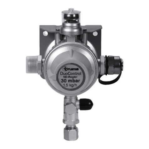
Truma DuoControl Operating instructions

Truma
Truma MonoControl User manual

Truma
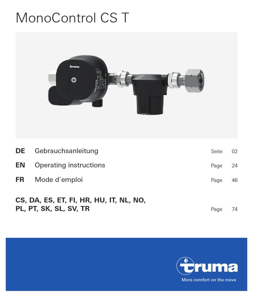
Truma MonoControl CS T User manual

Truma
Truma Duomatic L Plus Instruction sheet