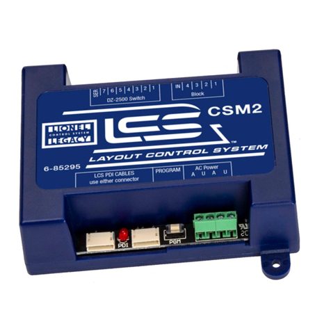
Lionel LCS AMC2 User manual

78-1641-250
3/18
Lionel
Accessory Motor
Controller 2 (AMC2)
Owner's Manual
LCS PDI CABLES
use either connector
AC Power
A U A U
PROGRAM
LIGHTS MOTORS
com
4
com
3
com
2
com
1
2
1
com
com
AMC2
6-81641

2
Thank You!
Your layout has always been more than the sum of its parts. But until now, combining
those parts into a complete system could be a challenge. Lionel’s new Layout Control
System or “LCS,” fulfills the LEGACY promise of integrated locomotive and layout control.
Table of Contents
What is Lionel’s Layout Control System?
How it works! 3
LCS AMC2 Module 4
Installing Your First LCS Device
Installing Your First LCS Device 5
The LCS DB-9 Cable with Power Supply 5
Installing a new LCS system with a Legacy Base 6
Installing a new LCS system with a Base-1L 7
Installing LCS with Legacy AND TrainMaster Command Bases 8-9
Installing a new LCS system with NO Command Base 10
Installing additional LCS devices
Installing additional LCS devices 11
Configuring Your AMC2
Configuring your AMC2 12
Connect accessory transformer to output power terminals 13
Understanding AMC2 software configuration 14
Base Address/TMCC ID 15
Motor Modes 15
Motor "Remember" 15
Configuring and using your AMC2 using and Accessory ID 16
Configuring and using your AMC2 using a Train or Engine ID 16-17
Accessory Examples
Wiring a single basic accessory 18
Wiring and operating a motor 20
Wiring and operating the Gantry Crane 19-20
Wiring and operating the Tug-of-War (DC motor operation) 21-22
Wiring and operating a Pullmor motor (AC motor operation) 23-24
Wiring and operating incandescent lights 25
Appendix
Operation of LEDs 26
Specifications of the LCS AMC2 27
Lionel Limited Warranty Policy & Service 28
The following Lionel marks are used throughout this Owner’s Manual and are protected under law. All rights
reserved.
Lionel®, TMCC®, LEGACY®, FasTrack®,TrainMaster®, CAB-1®Remote Controller, Pullmor®, TMCC®, Accessory
Motor Controller™, AMC™, Accessory Switch Controller™, ASC™, Track Power Controller 300™, TPC 300™, Block
Power Controller™, BPC™, SensorTrack™, LCS®

3
What is Lionel’s Layout Control System?
LCS doesn’t replace your existing Lionel Legacy Control system. It adds to it! You can control your
layout from Lionel Cab Remote controllers or from smart devices like an Apple iPad and run
locomotives, operate track switches, accessories and lighting. Create automatic events to control
passing locomotives and other layout accessories or switches.
LCS is a modular system, with each product offering unique features. No single LCS product
will do everything and not every layout will require every type of LCS device. But a fully realized LCS
system will likely include the following:
• A Lionel Command Base (Legacy or Base-1L) for locomotive control
• LCS WiFi so you can control your layout from smart devices like an iPad®
• LCS ASC2, to operate switches, lighting and accessories
• LCS BPC2 for block power control
• LCS SensorTrack (one or more) which adds a new level of interactivity with compatible Lionel
Legacy and Vision locomotives
• LCS SER2 for computer control and use of existing Lionel serial devices like the TPC-300 and
TPC-400
• LCS AMC2 for controlling accessory motors and lights
How it works!
Your Lionel Cab Remote sends commands to your Command Base. In turn, the base
controls your locomotives via a one-way communication link. LCS works in parallel with
your existing command base, adding a wired network of control modules. Spread across your
layout, these LCS modules operate switches, lighting, accessories and track power blocks. LCS
is bidirectional, meaning modules can send and receive commands.
And here’s where it all comes together: Since LCS can also send commands back through
the command base, LCS devices can operate your locomotives as well as your layout! For
example, a module like SensorTrack™ can make a loco blow a grade-crossing signal as it
passes. And the LCS WiFi module connects devices like an Apple iPad®to your layout so you
and your friends can easily operate switches, locos and more.
LCS WiFi
LCS SensorTrack
LCS SER2
LCS PDI cables connect modules
for bi-directional communication.
Command base controls locomotives,
one-way communication only
Figure 1. LCS doesn't replace your Lionel Command Base—it adds to it!

4
LCS AMC2 Module
The AMC2 module gives you control over your accessories like never before. When used in
conjunction with lights, the AMC-2 allows you to control bulb brightness from the CAB Remote
Controller. When used in conjunction with your accessories’ motors, the AMC-2 gives you control over
operation.
• Gives you precise motor and/or light control.
• Allows for operation of accessory speed, direction, or function from the CAB remote
controller or LCS app.
• Operate up to two motors and up to four incandescent lights.
• Various motor options allow for continuous motion, or proportional control, where the
motor turns only while you continuously rotate the throttle.
• Each light output can be dimmed independently.
The LCS AMC2 can only control incandescent light bulbs. It is not recommended to use
LED lighting.
Figure 2. LCS ASC2 Module
What is Lionel’s Layout Control System?
LCS PDI CABLES
use either connector
AC Power
A U A U
PROGRAM
LIGHTS MOTORS
com
4
com
3
com
2
com
1
2
1
com
com
AMC2
6-81641
Note!

5
Installing Your First LCS Device
The following section describes installation of a new LCS system. If you already have installed
your first LCS component, please skip ahead to the next section titled “Installing additional
LCS devices.”
When installing a new LCS system, the process you will follow depends on which (if any) Lionel
Command Base is to be connected to your LCS system. Following sections describe starting a new LCS
installation with a Legacy Base, a Base-1L or without any command base.
The LCS DB-9 Cable with Power Supply
Every LCS system requires exactly one 6-81499 LCS DB-9 Cable with Power Supply. This special
cable has three connectors: (A) a DB-9, with a “pig-tail” cable-mount power supply connector
(C) and also a 10-foot cable with an “LCS PDI” connector at its end (B). See below:
The cable receives power from the included DC wall-pack (12VDC at 1A). Power for each LCS
device is supplied through the single LCS data cable. The LCS DB-9 Cable with Power Supply wall-
pack is capable of powering dozens and dozens of LCS devices, depending on type. An additional
power booster/cable extender is available for extremely large LCS installations.
Figure 3. The LCS DB-9 Cable with Power Supply (sold separately)

6
Installing a new LCS system with a Legacy Base
To install a new LCS system on a layout with a Legacy Command Base:
1. Turn off power to your layout and Legacy Base
2. Connect the DC wall-pack to the female cable-mount connector of the LCS DB-9 Cable.
3. Connect the DB-9 connector of the LCS DB-9 Cable to your Legacy Command Base.
4. Connect the LCS PDI cable end of the LCS DB-9 Cable to either connector on your LCS device,
such as an LCS WiFi or LCS SensorTrack or any other Layout Control System product.
5. Restore power to your layout and Legacy Base.
6. Plug in the LCS wall-pack power supply.
If using a Legacy command base, it must have software rev 1.52 or
higher installed.
Your system should resemble the figure below.
Once connected and powered-up, the yellow LED on the Legacy Base will blink once every second.
With this setup, you can control Lionel locomotives and Layout Control System products using
a Legacy Remote(s) and optionally CAB-1L remote(s).
If you have additional LCS devices to install, see “Installing additional LCS devices.” If not, skip
ahead to the next section of this manual, “Configuring your LCS Device.”
Figure 4. Installing a new LCS system with a LEGACY Base
Note!
Installing Your First LCS Device

7
Installing a new LCS system with a Base-1L
To install a new LCS system on a layout with a Base-1L Command Base:
1. Turn off power to your layout and Base-1L
2. Connect the DC wall-pack to the female cable-mount connector of the LCS DB-9 Cable.
3. Connect the DB-9 connector of the LCS DB-9 Cable to your Base-1L.
4. Connect the LCS PDI cable end of the LCS DB-9 Cable to either connector on your LCS device,
such as an LCS WiFi or LCS SensorTrack or any other Layout Control System product.
5. Restore power to your layout and Base-1L.
6. Plug in the LCS wall-pack power supply.
Your system should resemble the figure below.
Once connected and powered-up, the red LED on the Base-1L will blink once every second.
With this setup, you can control Lionel locomotives and Layout Control System products using
a CAB-1L remote(s).
If you have additional LCS devices to install, see “Installing additional LCS devices.” If not,
skip ahead to the next section of this manual, “Configuring your LCS Device.”
Figure 5. Installing a new LCS system with a Base-1L
Installing Your First LCS Device

8
Installing LCS with Legacy AND TrainMaster Command Bases
The following instructions apply ONLY if you are using one or more original CAB-1 remotes with
a Legacy command base. It is not necessary to follow these instructions to use the CAB-1L remote
with a Legacy command base.
In order to complete this installation, you will need a CAB-1 remote, an original TMCC
Trainmaster command base, a Legacy Command Base with Legacy CAB-2 remote and the Legacy
serial Y cable (included with the Legacy command base).
This is the ONLY supported application for the Legacy Y cable. The “Command base” end
of the Legacy Serial Y cable cannot be directly connected to any accessory other than the
original TMCC TrainMaster command base.
To install a new LCS system on a layout with a Legacy Command Base, an original TMCC
Command Base and a Legacy Serial Y Cable:
1. Turn off power to your layout, Legacy Base and TMCC TrainMaster command base.
2. Connect the DC wall-pack to the female cable-mount connector of the LCS DB-9 Cable.
3. Connect the DB-9 connector of the Legacy Serial Y cable to your Legacy Command Base.
4. Connect the “Command Base” end of the Legacy Y cable to the DB-9 connector of your TMCC
Trainmaster Command Base.
5. Connect the DB-9 end of the LCS DB-9 Cable to the “Serial Comm” connector of the Legacy
Y cable.
6. Connect the LCS PDI cable end of the LCS DB-9 Cable to either connector on your LCS device,
such as an LCS WiFi or LCS SensorTrack or any other Layout Control System product.
7. Restore power to your layout, Legacy Base and TMCC TrainMaster command base.
8. Plug in the LCS wall-pack power supply.
Note!
Note! If using a Legacy command base, it must have software rev 1.52 or higher installed.
Installing Your First LCS Device

9
Installing LCS with Legacy AND TrainMaster Command Bases
(continued)
Your system should resemble the figure below.
Once connected and powered-up, the yellow LED on the Legacy Base will blink once every second.
With this setup, you can control Lionel locomotives and Layout Control System products using any
combination of LEGACY Remotes, CAB-1L remotes and original CAB-1 remotes.
If you have additional LCS devices to install, see “Installing additional LCS devices”. If not, skip
ahead to the next section of this manual, “Configuring your LCS Device.”
Figure 6. Installing LCS with Legacy AND TrainMaster Command Bases
Installing Your First LCS Device

10
Installing a new LCS system with NO Command Base
The Layout Control System can be used without a Lionel Command base. This would be
appropriate for a layout which only uses “conventional” or “transformer-controlled” locomotives
or a different type of locomotive control system such as DCC. An LCS WiFi is required, as are one other
LCS module (such as ASC2 or BPC2).
1. Connect the DC wall-pack to the female cable-mount connector of the LCS DB-9 Cable.
2. Connect the LCS PDI cable end of the LCS DB-9 Cable to either connector on your LCS WiFi.
3. Set the Base/No Base switch to “NO BASE.”
4. Leave the DB-9 connector of the LCS DB-9 Cable unconnected.
5. Plug in the LCS wall-pack power supply.
With this setup, you can control other Layout Control System products using compatible software
on smart devices connected via WiFi or from a computer using a wired serial connection via an
LCS SER2. Since this configuration does not include a command base, you will not be able to use
Lionel Cab Remotes, command-controlled locomotives or wireless command controlled switches or
accessories in conjunction with this LCS system.
If you have additional LCS devices to install, see “Installing additional LCS devices”. If not, skip
ahead to the next section of this manual, “Configuring your LCS Device.”
To install a new LCS system on a layout that does NOT include Lionel Command Base:
Installing Your First LCS Device

11
Installing additional LCS devices
This section describes adding a new device to an existing Layout Control System installation. If
you are installing a brand new LCS system, please refer to the previous section of this document,
“Installing Your First LCS Device.”
Adding additional LCS devices to an existing Layout Control System requires an additional
cable for each new device. These “LCS PDI Cables” come in a variety of pre-made lengths. They are
not included with LCS devices, and must be purchased separately. LCS PDI Cables are available in
a variety of lengths:
6-81500 - LCS PDI 1ft Cable
6-81501 - LCS PDI 3ft Cable
6-81502 - LCS PDI 10ft Cable
6-81503 - LCS PDI 20ft Cable
Each new device is connected via LCS PDI cables in a “daisy-chain” fashion (one to the next, and
so on). The order of devices in the “chain” is up to you. The only exception is that an LCS WiFi must
be the first device in the chain if no Lionel Command Base is present.
To connect each additional LCS device:
1. Find the “last” LCS device in the chain. One if its two LCS PDI connectors will be in use, the other
will be empty.
2. Using your chosen length LCS PDI Cable, connect one cable end to the unused LCS PDI connector
of the last LCS device in the chain.
3. Connect the second cable end to either of the LCS PDI connectors on your new LCS device (see
figure below). Your new LCS device is now the last one in the chain.
LCS PDI CABLES
use either connector
SER2
6-81326
LCS PDI CABLES
use either connector
WiFi
6-81325
To LCS module or
command base
Figure 7. Installing additional LCS devices

12
Configuring Your AMC2
The illustration below shows the name and location of each switch, connector and indicator
light on your LCS AMC2 module. The function of each is described on following pages.
A – Motor/Lights terminals should be connected to motors and incandescent
lights.
B – Label for screw terminals.
C – LCS PDI cable inputs. Use either connector.
D – Red LCS PDI activity indicator.
E – Program switch used to set the AMC2’s TMCC ID.
F – Input Power terminals.
Figure 8. AMC2 callouts.
There are three additional steps required to use your AMC2. They are:
1. Connect an accessory transformer to the Input Power Terminals.
2. Set the AMC2’s software configuration. In this step, you will choose switch vs. accessory
mode, base address and the latching or momentary sub-mode.
3. Wire your accessories or switches to the AMC2.
LCS PDI CABLES
use either connector
AC Power
A U A U
PROGRAM
LIGHTS MOTORS
com
4
com
3
com
2
com
1
2
1
com
com
AMC2
6-81641
A
B
C D E F

13
Connect Accessory Transformer to Input Power Terminals
Your AMC2 requires an external power source to operate its motor and light outputs. This
must be supplied from a separate accessory transformer and is required for both Accessory
or Switch configuration of your AMC2.
Connect an accessory transformer with an 12-14 VAC output to the AMC2’s front screw
terminal connections marked “A” and “U” as shown in Figure 9 below. If your installation
includes more than one AMC2, they can share the same accessory transformer as long as
the combined current draw does not exceed the capacity of the accessory transformer (See
Specifications, Electrical at the end of this document).
Figure 9. Connecting two AMC2 modules with LCS PDI cables and an accessory transformer
The AMC2 requires separate external power to operate its internal relays. Multiple AMC2
and/or BPC2 modules can be wired in a daisy-chain fashion as shown above.
When connected to lighting or accessories, the AMC2 will switch on and off the power to
these connected devices.
To connect the Input Power Terminals on your AMC2:
1. Attach one wire to the Common/Ground/U terminal of your transformer and connect it to
the POWER U terminal on the AMC2 unit.Do not connect this terminal to the outside rail.
2. Attach another wire to the Power/A terminal of your transformer and connect it to the
POWER A terminal on the AMC2 unit.
3. If your layout includes additional AMC2 or BPC2 devices, you can use the spare A and U
terminals on the first unit to jumper power to your next AMC2 device as shown in Figure 9.
Configuring Your AMC2
LCS PDI CABLES
use either connector
AC Power
A U A U
PROGRAM
LIGHTS MOTORS
com
4
com
3
com
2
com
1
2
1
com
com
AMC2
6-81641
LCS PDI CABLES
use either connector
AC Power
A U A U
PROGRAM
LIGHTS MOTORS
com
4
com
3
com
2
com
1
2
1
com
com
AMC2
6-81641
Accessory
Transformer
12-14VAC
A U

14
Understanding AMC2 Software Configuration
Your AMC2 software configuration is a single operation that sets three distinct features:
1. Accessory, Train or Engine Addressing
2. The operating mode for Motor 1 and if it should be automatically turned on when the
AMC2 is powered up.
3. The operating mode for Motor 2 and if it should be automatically turned on when the
AMC2 is powered up.
PGM
(Red LED Blinking)
1 or 2 Digit TMCC ID
Motor 1
Motor 2
Remember sequence state
Motor Modes
1. Continuions
2. Porportional
3. AC Motors
PGM
LED stops blinking.
End of sequence.
Remember sequence state.
LED stops blinking.
End of sequence.
Motor Modes
1. Continuions
2. Porportional
3. AC Motors
Figure 10. AMC2 configuration flowchart.
Configuring Your AMC2

15
Base Address/TMCC ID
Each AMC2 on your layout needs a unique combination of address type and TMCC ID.
The programming sequence begins with the choice of Accessory (ACC), Train/Track (TR) or
Engine (ENG). Following this, a one or two digital TMCC ID is chosen.
Do not use TMCC ID #99.
Motor Modes
You’ll choose the operating mode for the one or two connected motors during the
programming sequence. Modes one and two are for DC motors, mode three is for AC motors.
Mode 1 offers “continuous” motor operation of a DC motor. Here, setting the throttle
leaves the motor running at a constant speed and the direction button is used to change spin
direction—just like a locomotive. If you press the direction button while the motor if it is
spinning, it will stop. Use the throttle to start it turning again in the new direction. If you
wish, you can enable saving the motor setting during the programming setup for a Mode 1
motor which causes that motor’s speed and direction to be automatically restored on power-
up.
Mode 2 is “proportional" motor operation for a DC motor. Here, you have to keep rotating
the throttle for the motor to spin. When you turn the throttle faster, the motor speed increases.
When you stop turning the throttle, the motor stops too (this is comparable behavior to the
Lionel Command Controlled Gantry Crane). Changing from clockwise to counterclockwise
throttle motion will reverse the motor’s direction of rotation. The DIR button and enabling
saving the motor setting for in this mode are not particularly useful.
Mode 3 is for AC motors. This mode provides continuous operation. When the throttle
is turned clockwise, the motor speed spins faster. When the throttle stop turning, the motor
continues to run at its current speed. To slow or stop the motor, turn the throttle counter-
clockwise. The Direction button is ignored in this mode.
Motor "Remember"
When setting motor modes 1 and 3, you can set your AMC2 to remember the last
commanded speed and direction of that motor and restore it on power-up. Just tap the R
(rear coupler) button during programming and the AMC2 will “Remember” the last speed
the motor(s) were turning at when it’s power was removed. Then, when the AMC2 is turned
back on, it will automatically spin the motors at that same speed and direction. You can set
Remember separately for Motors 1 and 2.
Lighting levels will always be remembered. When the AMC2 is powered on, each of
the four lighting channels will return to it’s most recently set level.
Configuring Your AMC2
Note!
Note!

16
To configure your AMC2 options using an Accessory ID:
1. Turn power to your command base and LCS system on.
2. Press and hold the AMC2 PGM button for 1 seconds. The red LED will begin blinking
slowly.
3. On your Lionel cab remote, press ACC to choose Accessory configuration. Both the motors
and the lights must use the same address type, ACC in this case.
4. Enter the 1 or 2 digit address/TMCC ID. This ID is shared by all motors and lights. They
cannot be different.
5. Press SET. The red LED will blink quickly, then return to slow blinking.
At this point, you've configured your AMC2 for Accessory operation and set its TMCC ID. The
lighting outputs have no additional features, their programming is complete.
6. To program motor 1, Press AUX1, then 1, 2 or 3 depending on the motor type DC vs. AC
and the desired operating behavior.
7. If you want motor 1 to automatically come up to speed on power-up of your AMC2, tap the
R (rear coupler) button on your remote.
8. To program motor 2, Press AUX1, then 1, 2 or 3 depending on the motor type DC vs. AC
and the desired operating behavior.
9. If you want motor 2 to automatically come up to speed on power-up of your AMC2, tap the
R (rear coupler) button on your remote.
Depending on the options you select, the red LED may stop blinking automatically. If not, press
the PGM button on your AMC2. Once the blinking stops, the configuration process is complete.
To configure your AMC2 options using an TR or ENG ID:
1. Turn power to your command base and LCS system on.
2. Press and hold the AMC2 PGM button for 1 seconds. The red LED will begin blinking
slowly.
3. On your Lionel cab remote, press TR or ENG. Both the motors and the lights must use the
same address type, TR or ENG in this case.
4. Enter the 1 or 2 digit address/TMCC ID. This ID is shared by all motors and lights. They
cannot be different.
5. Press SET. The red LED will blink quickly, then return to slow blinking.
At this point, you've configured your AMC2 for Accessory operation and set its TMCC ID. The
lighting outputs have no additional features, their programming is complete.
6. To program motor 1, Press AUX1, then 1, 2 or 3 depending on the motor type DC vs. AC
and the desired operating behavior.
Configuring & using your AMC2 using an Accessory ID
Configuring & using your AMC2 using a Train or Engine ID
Configuring Your AMC2

17
7. If you want motor 1 to automatically come up to speed on power-up of your AMC2, tap the
R (rear coupler) button on your remote.
8. To program motor 2, Press AUX1, then 1, 2 or 3 depending on the motor type DC vs. AC
and the desired operating behavior.
9. If you want motor 2 to automatically come up to speed on power-up of your AMC2, tap the
R (rear coupler) button on your remote.
Depending on the options you select, the red LED may stop blinking automatically. If not, press
the PGM button on your AMC2. Once the blinking stops, the configuration process is complete.
Configuring & Using AMC2 using a Train or Engine ID continued
To operate your AMC2:
1. Depending on how you programmed your AMC2 in the previous step, press the ACC, TR or
ENG button on your remote.
2. Enter the one or two digit ID number matching the address set in the previous step.
3. Press AUX 1, then enter a single digit from 1 to 6 to choose the motor or the light you want
to control. 1 & 2 two are for the motors, 3-6 are for lights.
4. Turn the throttle clockwise to brighten that light or spin motor faster (modes 1 and 3).
5. Turn the throttle counter-clockwise to slow or stop the motor or dim/turn off that light.
6. To control a different motor or light, jump back to step 3 above (enter the 1 digit number
corresponding to the motor or light you want to control next).
To turn off the last operated motor or light:
1. Press and release the zero key (CAB1L) or the zero or R/reset button (CAB2).
Your handheld Cab Remote’s reset command (numeric 0) will turn off the most recently
operated motor or light. The other motor or lights will not be affected.
To turn off all motors and lights:
1. Press and hold the HALT button.
The Halt button will stop the entire layout, including all ASC2 operating motors and
illuminated lights.
1
2
3
4
5
6
Motor 1
Motor 2
Light 1
Light 2
Light 3
Light 4

18
Figure 11. An accessory motor wired to the Motor 1 terminal.
Wiring a single basic accessory
To connect a basic on/off accessory or light to your AMC2:
1. Attach one wire to the Power/A terminal on your accessory motor and connect it to the +
Motor 1 terminal of the AMC2.
2. Attach another wire to the Common/Ground/U terminal on the accessory motor and
connect it to the – Motor 1 terminal.
Accessory examples
LCS PDI CABLES
use either connector
AC Power
A U A U
PROGRAM
LIGHTS MOTORS
com
4
com
3
com
2
com
1
2
1
com
com
AMC2
6-81641
Accessory
Motor
+
–
Power/AGround/U

19
Wiring and operating a motor
Refer to the figure below to wire two motors to the AMC2 motor terminals.
Follow these steps to operate the motors:
Figure 12. Motor wiring diagram.
1. Press ACC on the CAB remote controller.
2. Using your CAB remote controller, enter the TMCC ID associated with the AMC2.
3. Press AUX 1, then press 1 for motor 1 and 2 for motor 2.
4. Rotate the throttle clockwise to turn on the motor/accessory.
5. Rotate the throttle counterclockwise to turn off the motor/accessory.
Accessory examples
LCS PDI CABLES
use either connector
AC Power
A U A U
PROGRAM
LIGHTS MOTORS
com
4
com
3
com
2
com
1
2
1
com
com
AMC2
6-81641
MOTOR 1
MOTOR 2
Power/A
Power/AGround/U
Ground/U

20
Wiring and Operating the Gantry Crane
Refer to the illustration below to wire the Gantry Crane for proportional motor setup.
Accessory examples
LCS PDI CABLES
use either connector
AC Power
A U A U
PROGRAM
LIGHTS MOTORS
com
4
com
3
com
2
com
1
2
1
com
com
AMC2
6-81641
CRANE ROTATIONAL
MOTOR
CRANE CABLE
MOTOR
Ground/U
Power/A
Ground/U Power/A
Figure 13. Gantry Crane wiring example.
To set up your crane:
1. Press PGM
2. Press ACC or TR or ENG
3. Select a 1 or 2 Digit TMCC ID
4. Press SET
5. Press AUX 1
6. Press 2 (Proportional)
7. Press AUX2
8. Press 2 (Proportional)
9. Press PGM
Table of contents
Other Lionel Controllers manuals