ST Sitronix ST7038 User manual

ST
Sitronix ST7038
Dot MatrixLCD Controller/Driver
Ver1.11/612007/01/25
FEATURES
l5 x 8dot matrixpossible
lSupportlowvoltage single poweroperation:
ØVDD, VDD2: 1.8to3.3V(typical)
lLCD Voltage Operation Range (V0/Vout)
ØProgrammable V0: 3 to 7V(V0)
ØExternalpowerapplied: Max. 12V(Vout)
lInterface
Ø6800-4bit / 8bitinterface
Ø8080-4bit / 8bitinterface
Ø3-line serialinterface
Ø4-line serialinterface
ØI
2
C interface
lSupportdisplay mode:
Ø8-COM x100-SEGand 80ICON
Ø16-COM x100-SEGand 80 ICON
Ø24-COM x80-SEGand 80 ICON
l10,240-bitCharacterGeneratorROM
(CGROM)stores 256characterfonts
l64 x 8-bitCharacterGeneratorRAM
(CGRAM)
l80 x 8-bitDisplayRAM(80 characters max.)
l16 x 5 bitICONRAM
lVariable instruction functions:
cleardisplay,returnhome, displayON/OFF,
cursorON/OFF,characterblink,cursorshift,
displayshift, doubleheightfont, ICONcontrol
and charactergeneration RAM
lResetcircuitthrough anexternal resetpin
lInternal oscillatororexternal clock
lBuilt-inlowpowerconsumption voltage
booster,regulatorand followercircuit
lBuilt-inhigh-accuracyvoltage regulator:
ØProgrammable outputrange: 3~7V
lCOM/SEGdirection selectable byinstruction
lSelectable CGRAM/CGROMsize
lPackage Type:COG
GENERALDESCRIPTION
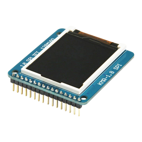
ST7038 dot-matrixliquid crystal displaycontrollercan
displayalphanumeric,Japanesekanacharactersand
symbols.It can be configuredtodriveadot-matrixliquid
crystaldisplayunderthecontrol ofamicroprocessorwith
4/8-bit6800-seriesor8080-series,3/4-lineserialorfastI2C
interface.Sinceallthefunctions(suchasdisplayRAM,
charactergeneratorROM/RAMand liquidcrystaldriver)
required fordrivingadot-matrixliquidcrystaldisplayare
internallyembedded in thischip,aminimal systemcan be
usedwiththiscontroller/driver.
The CharacterGeneratorROM ofST7038 has256 5x8dot
cellsand stores256 differentcharacter fonts(5x8dot).
ST7038 issuitable forlowvoltage supply(1.8Vto3.3V) and
is perfectlysuitableforanyportableproductwhichisdriven
bythe batteryandrequireslowpower consumption.
The displayresolutionofST7038 dot-matrixLCD drivercan
be either1-linex20 characters,2-line x20 charactersor
3-linex16 characterswith80-bit ICON.
ST7038 works alone without extracascaded drivers.
ProductName Charactergenerator ROMSize SupportCharacter
ST7038-0B256 English/ Europe/ Japan
ST7038
6800-4bit/ 8bitinterface
8080-4bit/ 8bitinterface
3-line/4-lineserial interface
(withoutI2Cinterface)
ST7038iI
2
Cinterface

ST7038
Ver1.12/612007/01/25
PADARRANGEMENT
lChipSize:5476.2umX906.2 um
lBump Pitch:
I/OPAD: 73um
COM/SEGPAD:45um
lBump size:
PADNo. 001 ~057:55umX60um
PADNo. 058 ~175:30umX80um
lBump Height:17um
lChipThickness:480um

ST7038
Ver1.13/612007/01/25
PADCENTER COORDINATES (3-line&2-linewithdoubleheight) Unit: um
PAD No. PIN Name X Y
1XRESET2543.915 379
2OSC 2424.915 379
3VDD 2350.675 379
4A0(RS) 2276.575 379
5CSB 2157.575 379
6/WR(RW)2084.575 379
7/RD(E) 1965.575 379
8DB[0]1892.575 379
9DB[1]1773.575 379
10 DB[2]1700.575 379
11DB[3]1581.575 379
12 DB[4]1508.575 379
13 DB[5]1389.575 379
14 DB[6]1316.575 379
15 DB[7]1197.575379
16 VSS 1124.575379
17 VSS 1051.575 379
18 VSS 978.575 379
19 VSS 905.575 379
20 PS0830.945 379
21 PS1711.945 379
22 PS2638.945 379
23 CLS519.945 379
24 TEST[0]447.945 379
25 TEST[1]298.945 379
26 TEST[2]223.945 379
27 TEST[3]48.945379
28 TEST[4]-26.055379
29 TEST[5]-201.055 379
30 VDD -276.94379
31 VDD -349.94379
32 VDD -422.94379
33 VDD2-495.94379
34 VDD2-568.94379
35 VDD2-641.94379
36 VOUT-714.94379
37 VOUT-787.94379
38 VOUT-860.94379
39 CAP3P-933.94379
40 CAP3P-1006.94 379
41 CAP1P-1079.94 379
42 CAP1P-1152.94 379
43 CAP1N-1225.94 379
44 CAP1N-1298.94 379
45 CAP1N-1371.94 379
46 CAP2P-1444.94 379
47 CAP2P-1517.94 379
48 CAP2N-1590.94 379
49 CAP2N-1663.94 379
50 CAP4P-1736.71 379
51 CAP4P-1809.94 379
52 VRS -1892.1379
53 V0-1965.26 379
54 V1-2053.56 379
PAD No. PIN Name X Y
55 V2-2126.56 379
56 V3-2199.56 379
57 V4-2272.56 379
58 COM[12]-2611.93 -369
59 COM[11]-2566.93 -369
60 COM[10]-2521.93 -369
61 COM[9]-2476.93 -369
62 COM[8]-2431.93 -369
63 COM[7]-2386.93 -369
64 COM[6]-2341.93 -369
65 COM[5]-2296.93 -369
66 NC -2251.93 -369
67 COM[4]-2206.93 -369
68 COM[3]-2161.93 -369
69 COM[2]-2116.93 -369
70 COM[1]-2071.93 -369
71 NC -2026.93 -369
72 NC -1981.93 -369
73 NC -1936.93 -369
74 NC -1891.93 -369
75 NC -1846.93 -369
76 NC -1801.93 -369
77 SEG[1]-1756.93 -369
78 SEG[2]-1711.93 -369
79 SEG[3]-1666.93 -369
80 SEG[4]-1621.93 -369
81 SEG[5]-1576.93 -369
82 SEG[6]-1531.93 -369
83 SEG[7]-1486.93 -369
84 SEG[8]-1441.93 -369
85 SEG[9]-1396.93 -369
86 SEG[10]-1351.93 -369
87 SEG[11]-1306.93 -369
88 SEG[12]-1261.93 -369
89 SEG[13]-1216.93 -369
90 SEG[14]-1171.93 -369
91 SEG[15]-1126.93 -369
92 SEG[16]-1081.93 -369
93 SEG[17]-1036.93 -369
94 SEG[18]-991.93-369
95 SEG[19]-946.93-369
96 SEG[20]-901.93-369
97 SEG[21]-856.93-369
98 SEG[22]-811.93 -369
99 SEG[23]-766.93-369
100 SEG[24]-721.93-369
101 SEG[25]-676.93-369
102 SEG[26]-631.93-369
103 SEG[27]-586.93-369
104 SEG[28]-541.93-369
105 SEG[29]-496.93-369
106 SEG[30]-451.93-369
107 SEG[31]-406.93-369
108 SEG[32]-361.93-369

ST7038
Ver1.14/612007/01/25
PAD No. PIN Name X Y
109 SEG[33]-316.93-369
110 SEG[34]-271.93-369
111SEG[35]-226.93-369
112 SEG[36]-181.93-369
113 SEG[37]-136.93-369
114 SEG[38]-91.93 -369
115 SEG[39]-46.93 -369
116 SEG[40]-1.93 -369
117 SEG[41]43.07 -369
118 SEG[42]88.07 -369
119 SEG[43]133.07-369
120 SEG[44]178.07-369
121 SEG[45]223.07-369
122 SEG[46]268.07-369
123 SEG[47]313.07-369
124 SEG[48]358.07-369
125 SEG[49]403.07-369
126 SEG[50]448.07-369
127 SEG[51]493.07-369
128 SEG[52]538.07-369
129 SEG[53]583.07-369
130 SEG[54]628.07-369
131 SEG[55]673.07-369
132 SEG[56]718.07-369
133 SEG[57]763.07-369
134 SEG[58]808.07-369
135 SEG[59]853.07-369
136 SEG[60]898.07-369
137 SEG[61]943.07-369
138 SEG[62]988.07-369
139 SEG[63]1033.07 -369
140 SEG[64]1078.07 -369
141 SEG[65]1123.07 -369
142 SEG[66]1168.07 -369
143 SEG[67]1213.07 -369
144 SEG[68]1258.07 -369
145 SEG[69]1303.07 -369
146 SEG[70]1348.07 -369
147 SEG[71]1393.07 -369
148 SEG[72]1438.07 -369
149 SEG[73]1483.07 -369
150 SEG[74]1528.07 -369
151 SEG[75]1573.07 -369
152 SEG[76]1618.07 -369
153 SEG[77]1663.07 -369
154 SEG[78]1708.07 -369
155 SEG[79]1753.07 -369
156 SEG[80]1798.07 -369
157 NC 1843.07 -369
158 NC 1888.07 -369
159 NC 1933.07 -369
160 NC 1978.07 -369
161 NC 2023.07 -369
162 NC 2068.07 -369
163 COM[13]2113.07 -369
PAD No. PIN Name X Y
164 COM[14]2158.07 -369
165 COM[15]2203.07 -369
166 COM[16]2248.07 -369
167 COM[17]2293.07 -369
168 COM[18]2338.07 -369
169 COM[19]2383.07 -369
170 COM[20]2428.07 -369
171 COM[21]2473.07 -369
172 COM[22]2518.07 -369
173 COM[23]2563.07 -369
174 COM[24]2608.07 -369
175 COMI22653.07 -369

ST7038
Ver1.15/612007/01/25
PADCENTER COORDINATES (2-line&1-linewithdoubleheight) Unit: um
PAD No. PIN Name X Y
1XRESET2543.915 379
2OSC 2424.915 379
3VDD 2350.675 379
4A0(RS) 2276.575 379
5CSB 2157.575 379
6/WR(RW)2084.575 379
7/RD(E) 1965.575 379
8DB[0]1892.575 379
9DB[1]1773.575 379
10 DB[2]1700.575 379
11DB[3]1581.575 379
12 DB[4]1508.575 379
13 DB[5]1389.575 379
14 DB[6]1316.575 379
15 DB[7]1197.575379
16 VSS 1124.575379
17 VSS 1051.575 379
18 VSS 978.575 379
19 VSS 905.575 379
20 PS0830.945 379
21 PS1711.945 379
22 PS2638.945 379
23 CLS519.945 379
24 TEST[0]447.945 379
25 TEST[1]298.945 379
26 TEST[2]223.945 379
27 TEST[3]48.945379
28 TEST[4]-26.055379
29 TEST[5]-201.055 379
30 VDD -276.94379
31 VDD -349.94379
32 VDD -422.94379
33 VDD2-495.94379
34 VDD2-568.94379
35 VDD2-641.94379
36 VOUT-714.94379
37 VOUT-787.94379
38 VOUT-860.94379
39 CPA3P-933.94379
40 CAP3P-1006.94 379
41 CAP1P-1079.94 379
42 CAP1P-1152.94 379
43 CAP1N-1225.94 379
44 CAP1N-1298.94 379
45 CAP1N-1371.94 379
46 CAP2P-1444.94 379
47 CAP2P-1517.94 379
48 CAP2N-1590.94 379
49 CAP2N-1663.94 379
50 CAP4P-1736.71 379
51 CAP4P-1809.94 379
52 VRS -1892.1379
53 V0-1965.26 379
54 V1-2053.56 379
PAD No. PIN Name X Y
55 V2-2126.56 379
56 V3-2199.56 379
57 V4-2272.56 379
58 COM[8]-2611.93 -369
59 COM[7]-2566.93 -369
60 COM[6]-2521.93 -369
61 COM[5]-2476.93 -369
62 COM[4]-2431.93 -369
63 COM[3]-2386.93 -369
64 COM[2]-2341.93 -369
65 COM[1]-2296.93 -369
66 COMI1-2251.93 -369
67 SEG[1]-2206.93 -369
68 SEG[2]-2161.93 -369
69 SEG[3]-2116.93 -369
70 SEG[4]-2071.93 -369
71 SEG[5]-2026.93 -369
72 SEG[6]-1981.93 -369
73 SEG[7]-1936.93 -369
74 SEG[8]-1891.93 -369
75 SEG[9]-1846.93 -369
76 SEG[10]-1801.93 -369
77 SEG[11]-1756.93 -369
78 SEG[12]-1711.93 -369
79 SEG[13]-1666.93 -369
80 SEG[14]-1621.93 -369
81 SEG[15]-1576.93 -369
82 SEG[16]-1531.93 -369
83 SEG[17]-1486.93 -369
84 SEG[18]-1441.93 -369
85 SEG[19]-1396.93 -369
86 SEG[20]-1351.93 -369
87 SEG[21]-1306.93 -369
88 SEG[22]-1261.93 -369
89 SEG[23]-1216.93 -369
90 SEG[24]-1171.93 -369
91 SEG[25]-1126.93 -369
92 SEG[26]-1081.93 -369
93 SEG[27]-1036.93 -369
94 SEG[28]-991.93-369
95 SEG[29]-946.93-369
96 SEG[30]-901.93-369
97 SEG[31]-856.93-369
98 SEG[32]-811.93 -369
99 SEG[33]-766.93-369
100 SEG[34]-721.93-369
101 SEG[35]-676.93-369
102 SEG[36]-631.93-369
103 SEG[37]-586.93-369
104 SEG[38]-541.93-369
105 SEG[39]-496.93-369
106 SEG[40]-451.93-369
107 SEG[41]-406.93-369
108 SEG[42]-361.93-369

ST7038
Ver1.16/612007/01/25
PAD No. PIN Name X Y
109 SEG[43]-316.93-369
110 SEG[44]-271.93-369
111SEG[45]-226.93-369
112 SEG[46]-181.93-369
113 SEG[47]-136.93-369
114 SEG[48]-91.93 -369
115 SEG[49]-46.93 -369
116 SEG[50]-1.93 -369
117 SEG[51]43.07 -369
118 SEG[52]88.07 -369
119 SEG[53]133.07-369
120 SEG[54]178.07-369
121 SEG[55]223.07-369
122 SEG[56]268.07-369
123 SEG[57]313.07-369
124 SEG[58]358.07-369
125 SEG[59]403.07-369
126 SEG[60]448.07-369
127 SEG[61]493.07-369
128 SEG[62]538.07-369
129 SEG[63]583.07-369
130 SEG[64]628.07-369
131 SEG[65]673.07-369
132 SEG[66]718.07-369
133 SEG[67]763.07-369
134 SEG[68]808.07-369
135 SEG[69]853.07-369
136 SEG[70]898.07-369
137 SEG[71]943.07-369
138 SEG[72]988.07-369
139 SEG[73]1033.07 -369
140 SEG[74]1078.07 -369
141 SEG[75]1123.07 -369
142 SEG[76]1168.07 -369
143 SEG[77]1213.07 -369
144 SEG[78]1258.07 -369
145 SEG[79]1303.07 -369
146 SEG[80]1348.07 -369
147 SEG[81]1393.07 -369
148 SEG[82]1438.07 -369
149 SEG[83]1483.07 -369
150 SEG[84]1528.07 -369
151 SEG[85]1573.07 -369
152 SEG[86]1618.07 -369
153 SEG[87]1663.07 -369
154 SEG[88]1708.07 -369
155 SEG[89]1753.07 -369
156 SEG[90]1798.07 -369
157 SEG[91]1843.07 -369
158 SEG[92]1888.07 -369
159 SEG[93]1933.07 -369
160 SEG[94]1978.07 -369
161 SEG[95]2023.07 -369
162 SEG[96]2068.07 -369
163 SEG[97]2113.07 -369
PAD No. PIN Name X Y
164 SEG[98]2158.07 -369
165 SEG[99]2203.07 -369
166 SEG[100]2248.07 -369
167 COM[9]2293.07 -369
168 COM[10]2338.07 -369
169 COM[11]2383.07 -369
170 COM[12]2428.07 -369
171 COM[13]2473.07 -369
172 COM[14]2518.07 -369
173 COM[15]2563.07 -369
174 COM[16]2608.07 -369
175 COMI22653.07 -369

ST7038
Ver1.17/612007/01/25
PADCENTER COORDINATES (1-line, SHLC= H”)Unit: um
PAD No. PIN Name X Y
1XRESET2543.915 379
2OSC 2424.915 379
3VDD 2350.675 379
4A0(RS) 2276.575 379
5CSB 2157.575 379
6/WR(RW)2084.575 379
7/RD(E) 1965.575 379
8DB[0]1892.575 379
9DB[1]1773.575 379
10 DB[2]1700.575 379
11DB[3]1581.575 379
12 DB[4]1508.575 379
13 DB[5]1389.575 379
14 DB[6]1316.575 379
15 DB[7]1197.575379
16 VSS 1124.575379
17 VSS 1051.575 379
18 VSS 978.575 379
19 VSS 905.575 379
20 PS0830.945 379
21 PS1711.945 379
22 PS2638.945 379
23 CLS519.945 379
24 TEST[0]447.945 379
25 TEST[1]298.945 379
26 TEST[2]223.945 379
27 TEST[3]48.945379
28 TEST[4]-26.055379
29 TEST[5]-201.055 379
30 VDD -276.94379
31 VDD -349.94379
32 VDD -422.94379
33 VDD2-495.94379
34 VDD2-568.94379
35 VDD2-641.94379
36 VOUT-714.94379
37 VOUT-787.94379
38 VOUT-860.94379
39 CAP3P-933.94379
40 CAP3P-1006.94 379
41 CAP1P-1079.94 379
42 CAP1P-1152.94 379
43 CAP1N-1225.94 379
44 CAP1N-1298.94 379
45 CAP1N-1371.94 379
46 CAP2P-1444.94 379
47 CAP2P-1517.94 379
48 CAP2N-1590.94 379
49 CAP2N-1663.94 379
50 CAP4P-1736.71 379
51 CAP4P-1809.94 379
52 VRS -1892.1379
53 V0-1965.26 379
54 V1-2053.56 379
PAD No. PIN Name X Y
55 V2-2126.56 379
56 V3-2199.56 379
57 V4-2272.56 379
58 COM[8]-2611.93 -369
59 COM[7]-2566.93 -369
60 COM[6]-2521.93 -369
61 COM[5]-2476.93 -369
62 COM[4]-2431.93 -369
63 COM[3]-2386.93 -369
64 COM[2]-2341.93 -369
65 COM[1]-2296.93 -369
66 COMI1-2251.93 -369
67 SEG[1]-2206.93 -369
68 SEG[2]-2161.93 -369
69 SEG[3]-2116.93 -369
70 SEG[4]-2071.93 -369
71 SEG[5]-2026.93 -369
72 SEG[6]-1981.93 -369
73 SEG[7]-1936.93 -369
74 SEG[8]-1891.93 -369
75 SEG[9]-1846.93 -369
76 SEG[10]-1801.93 -369
77 SEG[11]-1756.93 -369
78 SEG[12]-1711.93 -369
79 SEG[13]-1666.93 -369
80 SEG[14]-1621.93 -369
81 SEG[15]-1576.93 -369
82 SEG[16]-1531.93 -369
83 SEG[17]-1486.93 -369
84 SEG[18]-1441.93 -369
85 SEG[19]-1396.93 -369
86 SEG[20]-1351.93 -369
87 SEG[21]-1306.93 -369
88 SEG[22]-1261.93 -369
89 SEG[23]-1216.93 -369
90 SEG[24]-1171.93 -369
91 SEG[25]-1126.93 -369
92 SEG[26]-1081.93 -369
93 SEG[27]-1036.93 -369
94 SEG[28]-991.93-369
95 SEG[29]-946.93-369
96 SEG[30]-901.93-369
97 SEG[31]-856.93-369
98 SEG[32]-811.93 -369
99 SEG[33]-766.93-369
100 SEG[34]-721.93-369
101 SEG[35]-676.93-369
102 SEG[36]-631.93-369
103 SEG[37]-586.93-369
104 SEG[38]-541.93-369
105 SEG[39]-496.93-369
106 SEG[40]-451.93-369
107 SEG[41]-406.93-369
108 SEG[42]-361.93-369

ST7038
Ver1.18/612007/01/25
PAD No. PIN Name X Y
109 SEG[43]-316.93-369
110 SEG[44]-271.93-369
111SEG[45]-226.93-369
112 SEG[46]-181.93-369
113 SEG[47]-136.93-369
114 SEG[48]-91.93 -369
115 SEG[49]-46.93 -369
116 SEG[50]-1.93 -369
117 SEG[51]43.07 -369
118 SEG[52]88.07 -369
119 SEG[53]133.07-369
120 SEG[54]178.07-369
121 SEG[55]223.07-369
122 SEG[56]268.07-369
123 SEG[57]313.07-369
124 SEG[58]358.07-369
125 SEG[59]403.07-369
126 SEG[60]448.07-369
127 SEG[61]493.07-369
128 SEG[62]538.07-369
129 SEG[63]583.07-369
130 SEG[64]628.07-369
131 SEG[65]673.07-369
132 SEG[66]718.07-369
133 SEG[67]763.07-369
134 SEG[68]808.07-369
135 SEG[69]853.07-369
136 SEG[70]898.07-369
137 SEG[71]943.07-369
138 SEG[72]988.07-369
139 SEG[73]1033.07 -369
140 SEG[74]1078.07 -369
141 SEG[75]1123.07 -369
142 SEG[76]1168.07 -369
143 SEG[77]1213.07 -369
144 SEG[78]1258.07 -369
145 SEG[79]1303.07 -369
146 SEG[80]1348.07 -369
147 SEG[81]1393.07 -369
148 SEG[82]1438.07 -369
149 SEG[83]1483.07 -369
150 SEG[84]1528.07 -369
151 SEG[85]1573.07 -369
152 SEG[86]1618.07 -369
153 SEG[87]1663.07 -369
154 SEG[88]1708.07 -369
155 SEG[89]1753.07 -369
156 SEG[90]1798.07 -369
157 SEG[91]1843.07 -369
158 SEG[92]1888.07 -369
159 SEG[93]1933.07 -369
160 SEG[94]1978.07 -369
161 SEG[95]2023.07 -369
162 SEG[96]2068.07 -369
163 SEG[97]2113.07 -369
PAD No. PIN Name X Y
164 SEG[98]2158.07 -369
165 SEG[99]2203.07 -369
166 SEG[100]2248.07 -369
167 NC 2293.07 -369
168 NC 2338.07 -369
169 NC 2383.07 -369
170 NC 2428.07 -369
171 NC 2473.07 -369
172 NC 2518.07 -369
173 NC 2563.07 -369
174 NC 2608.07 -369
175 COMI22653.07 -369

ST7038
Ver1.19/612007/01/25
PADCENTER COORDINATES (1-line, SHLC= L”)Unit: um
PAD No. PIN Name X Y
1XRESET2543.915 379
2OSC 2424.915 379
3VDD 2350.675 379
4A0(RS) 2276.575 379
5CSB 2157.575 379
6/WR(RW)2084.575 379
7/RD(E) 1965.575 379
8DB[0]1892.575 379
9DB[1]1773.575 379
10 DB[2]1700.575 379
11DB[3]1581.575 379
12 DB[4]1508.575 379
13 DB[5]1389.575 379
14 DB[6]1316.575 379
15 DB[7]1197.575379
16 VSS 1124.575379
17 VSS 1051.575 379
18 VSS 978.575 379
19 VSS 905.575 379
20 PS0830.945 379
21 PS1711.945 379
22 PS2638.945 379
23 CLS519.945 379
24 TEST[0]447.945 379
25 TEST[1]298.945 379
26 TEST[2]223.945 379
27 TEST[3]48.945379
28 TEST[4]-26.055379
29 TEST[5]-201.055 379
30 VDD -276.94379
31 VDD -349.94379
32 VDD -422.94379
33 VDD2-495.94379
34 VDD2-568.94379
35 VDD2-641.94379
36 VOUT-714.94379
37 VOUT-787.94379
38 VOUT-860.94379
39 CAP3P-933.94379
40 CAP3P-1006.94 379
41 CAP1P-1079.94 379
42 CAP1P-1152.94 379
43 CAP1N-1225.94 379
44 CAP1N-1298.94 379
45 CAP1N-1371.94 379
46 CAP2P-1444.94 379
47 CAP2P-1517.94 379
48 CAP2N-1590.94 379
49 CAP2N-1663.94 379
50 CAP4P-1736.71 379
51 CAP4P-1809.94 379
52 VRS -1892.1379
53 V0-1965.26 379
54 V1-2053.56 379
PAD No. PIN Name X Y
55 V2-2126.56 379
56 V3-2199.56 379
57 V4-2272.56 379
58 NC -2611.93 -369
59 NC -2566.93 -369
60 NC -2521.93 -369
61 NC -2476.93 -369
62 NC -2431.93 -369
63 NC -2386.93 -369
64 NC -2341.93 -369
65 NC -2296.93 -369
66 COMI1-2251.93 -369
67 SEG[1]-2206.93 -369
68 SEG[2]-2161.93 -369
69 SEG[3]-2116.93 -369
70 SEG[4]-2071.93 -369
71 SEG[5]-2026.93 -369
72 SEG[6]-1981.93 -369
73 SEG[7]-1936.93 -369
74 SEG[8]-1891.93 -369
75 SEG[9]-1846.93 -369
76 SEG[10]-1801.93 -369
77 SEG[11]-1756.93 -369
78 SEG[12]-1711.93 -369
79 SEG[13]-1666.93 -369
80 SEG[14]-1621.93 -369
81 SEG[15]-1576.93 -369
82 SEG[16]-1531.93 -369
83 SEG[17]-1486.93 -369
84 SEG[18]-1441.93 -369
85 SEG[19]-1396.93 -369
86 SEG[20]-1351.93 -369
87 SEG[21]-1306.93 -369
88 SEG[22]-1261.93 -369
89 SEG[23]-1216.93 -369
90 SEG[24]-1171.93 -369
91 SEG[25]-1126.93 -369
92 SEG[26]-1081.93 -369
93 SEG[27]-1036.93 -369
94 SEG[28]-991.93-369
95 SEG[29]-946.93-369
96 SEG[30]-901.93-369
97 SEG[31]-856.93-369
98 SEG[32]-811.93 -369
99 SEG[33]-766.93-369
100 SEG[34]-721.93-369
101 SEG[35]-676.93-369
102 SEG[36]-631.93-369
103 SEG[37]-586.93-369
104 SEG[38]-541.93-369
105 SEG[39]-496.93-369
106 SEG[40]-451.93-369
107 SEG[41]-406.93-369
108 SEG[42]-361.93-369

ST7038
Ver1.110/61 2007/01/25
PAD No. PIN Name X Y
109 SEG[43]-316.93-369
110 SEG[44]-271.93-369
111SEG[45]-226.93-369
112 SEG[46]-181.93-369
113 SEG[47]-136.93-369
114 SEG[48]-91.93 -369
115 SEG[49]-46.93 -369
116 SEG[50]-1.93 -369
117 SEG[51]43.07 -369
118 SEG[52]88.07 -369
119 SEG[53]133.07-369
120 SEG[54]178.07-369
121 SEG[55]223.07-369
122 SEG[56]268.07-369
123 SEG[57]313.07-369
124 SEG[58]358.07-369
125 SEG[59]403.07-369
126 SEG[60]448.07-369
127 SEG[61]493.07-369
128 SEG[62]538.07-369
129 SEG[63]583.07-369
130 SEG[64]628.07-369
131 SEG[65]673.07-369
132 SEG[66]718.07-369
133 SEG[67]763.07-369
134 SEG[68]808.07-369
135 SEG[69]853.07-369
136 SEG[70]898.07-369
137 SEG[71]943.07-369
138 SEG[72]988.07-369
139 SEG[73]1033.07 -369
140 SEG[74]1078.07 -369
141 SEG[75]1123.07 -369
142 SEG[76]1168.07 -369
143 SEG[77]1213.07 -369
144 SEG[78]1258.07 -369
145 SEG[79]1303.07 -369
146 SEG[80]1348.07 -369
147 SEG[81]1393.07 -369
148 SEG[82]1438.07 -369
149 SEG[83]1483.07 -369
150 SEG[84]1528.07 -369
151 SEG[85]1573.07 -369
152 SEG[86]1618.07 -369
153 SEG[87]1663.07 -369
154 SEG[88]1708.07 -369
155 SEG[89]1753.07 -369
156 SEG[90]1798.07 -369
157 SEG[91]1843.07 -369
158 SEG[92]1888.07 -369
159 SEG[93]1933.07 -369
160 SEG[94]1978.07 -369
161 SEG[95]2023.07 -369
162 SEG[96]2068.07 -369
163 SEG[97]2113.07 -369
PAD No. PIN Name X Y
164 SEG[98]2158.07 -369
165 SEG[99]2203.07 -369
166 SEG[100]2248.07 -369
167 COM[8]2293.07 -369
168 COM[7]2338.07 -369
169 COM[6]2383.07 -369
170 COM[5]2428.07 -369
171 COM[4]2473.07 -369
172 COM[3]2518.07 -369
173 COM[2]2563.07 -369
174 COM[1]2608.07 -369
175 COMI22653.07 -369

ST7038
Ver1.111/612007/01/25
BLOCK DIAGRAM
RW
Reset
circuit CPG
Timing
generator
Instruction
register(IR)
Instruction
decoder Displaydata
RAM
(DDRAM)
80x8bits
24-bit
shift
register
Common
signal
driver
100-bit
latch
circuit
100-bit
shift
register
Segment
signal
driver
LCD drive
voltage
follower
Address
counter
(AC)
Data
register
(DR)
Busy
flag
MPU
interface
Input/
output
buffer
Character
generator RAM
(CGRAM)
64bytes
Character
generator ROM
(CGROM)
10240 bits
Cursor
and
blink
controller
Parallel/serial converter
and
attributecircuit
RS
E
DB4to
DB7
DB0to
DB3
VDD
OSC
COM1to
COM16
(or24)
SEG1to
SEG100
(or 80)
XRESET
VSS
Voltage
booster
circuit
COMI
CLS
V0~V4
VOUT
PS0
CAP1P
CAP1N
ICONRAM
80 bits
CSB
PS1
CAP2P
CAP2N
PS2
CAP3P
CAP4P

ST7038
Ver1.112/61 2007/01/25
PIN DESCRIPTION
Name I/O Interfaced
with Function
XRESETIMPU External resetpin.
Lowactive.
A0(RS) IMPU
Register select.
0: Instructionregister (for writing)
Busyflag& addresscounter (for reading)
1: Dataregister (for writeandread)
ThisPin must connect to VDD”when it isnotused
/WR(R/W)IMPU
8080-series interface(/WR):
Writeenable signalinput pin (lowactive).
6800-series interface(R/W):
Select reador write
R/W=0:Write
R/W=1: Read
ThisPin must connect to VDD”when serialmode is selected.
/RD(E) IMPU
8080-series interface(/RD):
Read enablesignalinputpin(lowactive).
6800-series interface(E):
Datastrobe signalinput. It startsdataread/write(high active).
ThisPin must connect to VDD”when serialmode is selected.
CSB IMPU
Chip selectin parallel/serialinterface(lowactive). Inserialinterface,the
falling edge of CSB will resetthe internalshift registerandcounter.
ThisPin must connect to VDD”when I2C modeisselected.
Forparallel 8-bit parallel interface:
DB7~DB0are8-bit bi-directional databusand shouldbe connected to8-bit
databusof the microprocessor.
When the chip select isnotactive(CSB=H), DB7~DB0arehigh impedance.
Forparallel 4-bit parallel interface:
DB7~DB4areusedfordatatransfer between MPU and ST7038;
DB3~DB0arenot usedandmust beleft OPEN orconnectedtoVDD.
Forserialinterface (3-line and4-line):
DB7: serial data input (SI);
DB6: serial clockinput (SCL).
DB5~DB0arenot usedandmust beleft OPEN orconnectedtoVDD.
DB7~DB0I/OMPU
ForI2C interface:
DB7~DB6: slaveaddresses(SA1~SA0) andmustbe fixed to H”or L”;
DB5~DB3: serialdataoutput(SDA-out);
DB2~DB1: serialdatainput (SDA-in);
DB0: serial clockinput (SCL).
DB1~DB5must beconnectedtogether (SDA).
The ITOresistanceonSDA/SCLwill formavoltage dividerwiththe pull-up
resistor on system. Tokeepthesignal qualitybetter,customersshould keep
the ITOresistanceaslowaspossible.
PS2~PS0IMPU
Parallel / Serialaccess mode selection
PS2
PS1
PS0
Access mode
0008080-seriesparallelMPU interface
0016800-seriesparallelMPU interface
0104-lineserialMPU interface
0113-lineserialMPU interface
100I
2
C serial MPU interface

ST7038
Ver1.113/61 2007/01/25
Name I/O Interfaced
with Function
COM1~COM16
(COM1~COM24)
OLCD
Commondriver outputs.
Signalsthatarenotused will outputthe non-selection waveform.For
example,COM9toCOM16 outputthenon-selectionwaveformin 1-line
displaymode.
COMI1, COMI2OLCD Commondriver outputsfor ICON.
SEG1~SEG100
(SEG1~SEG80) OLCD
Segment driver outputs.
The outputmapisdifferentfromdisplaymodes(3-line,2-line and 1-line)
pleaserefer toTable9for detailed outputmap.
CAP1P, CAP2P,
CAP3P, CAP4P,
CAP1N, CAP2N
PowerPower For voltage booster circuit (VDD-VSS).
External capacitor about0.1uF~4.7uF.
VOUTPowerPower Built-inVoltageBoosteroutput.
If using external boostercircuit, thispinisused asthe power input.
V0~V4PowerPower
Power supplyforLCD drive
V0: built-inVoltageRegulatoroutput.
If using external regulator circuit, thispinisused asthe power input.
Internalregulator programmable range: V0- VSS =7V (Max);
External power endurance: V0- VSS =12V(Max).
V1~V4: built-in voltagefollower outputs.
If using external follower circuit, connect theexternal power tothesepins.
Pleasealwayskeep the voltagerelationbetween thesepinstobe:
VOUT>V0>V1>V2>V3> V4>VSS
VDD PowerPowerPower for digital circuits. Connect to1.8V~3.3Vpower source.
VDD2PowerPowerPower for analog circuit.Connect to1.8V~3.3Vpower source.
VSS PowerPowerGround.
VRS PowerPower Reserved tomonitor theinternal VoltageRegulator referencelevel.
Must be left open.
CLSIOption
Select touseinternal/external oscillationsystem.
0: External clockwill beinput throughOSC pin;
1: Using internal clock and theOSC pin mustbe fixed toVDD.
OSC IOscillation
External clock input pin.
If using external clock,connect thispintothe clocksource.
If using internal clock, connectthispintoVDD.
TEST0~TEST5-Test Only
Reserved for testing only. Must be leftopen.
Notes:
1.Pleaseconnectall unused input pinstoVDD.
2.The microprocessorinterfacepins(CSB, /WR, /RD, A0andD7~D0) shouldnotbe left floating inanyoperation mode.
Recommended ITOResistance Limitation
PIN Name ITOResistance
(VDD2 ≥2.4V)
ITOResistance
(VDD2<2.4V)
PS2~PS0, CLS, OSC*1 NoLimitation NoLimitation
TEST0~TEST5, VRS Floating Floating
VDD, VDD2, VSS, VOUT<100Ω<80Ω
A0, /WR(R/W), /RD(E), CSB, DB0~DB7*2,<1KΩ<800Ω
V0~V4, CAP1P, CAP1N, CAP2P, CAP2N, CAP3P, CAP4P<500Ω*3 <200Ω*3
XRESET<10KΩ*4 <8KΩ*4
Notes:
1.If using internal clock, OSC isconnecttoVDD andtherewill be NoLimitation”on itsITOresistance.
If using external clock, the ITOresistanceof OSC shouldbe keptlower than 500Ωtocontrol theclocksignal quality.
2.If using I2C interfacemode, theresistanceof SDAsignalshould belower than300Ω.
3.Toget abetterpower systemefficiency, the recommended ITOresistancevalueshouldbelower than 300Ω.

ST7038
Ver1.114/61 2007/01/25
FUNCTION DESCRIPTION
MICROPROCESSOR INTERFACE
ChipSelectInput
The CSB pinisusedforchipselection.ST7038 caninterfacewithanMPU when CSB is"L".WhenCSB issetto H”,the
control signalinputs,A0,/RD(E) and/WR(R/W),aredisabledandDB0toDB7aresettobe high impedance.Whenusing
3-lineor 4-lineserialinterface,the internal shift register and counter arereset rightafterthefallingedgeofCSB.
Parallel / Serial Interface
ST7038 hasfiveinterfacemodestointerfacewithan MPU, whicharethree serial interfacesandtwoparallel interfaces.
TheseinterfacemodesareselectedbyPS2~PS0pinsasshownbelow.
Table1Parallel /SerialInterfaceModes
Parallel /Serial PS2 PS1 PS0 CSB InterfaceMode
LLLCSB 8000-seriesparallelMPU interfacemode
Parallel LLHCSB 6880-seriesparallelMPU interfacemode
LHLCSB 4-lineSPI (Serial PeripheralInterface) mode
LHHCSB 3-lineSPI (Serial PeripheralInterface) mode
Serial
HLL-- I
2
C interfacemode
Parallel Interface (PS[2:0]="0, 0, X")
The 8-bitbi-directional databusis used in parallel interfaceand the type ofMPU is selected byPS0asshownin Table 2.The
accesstype isdetermined bysignalsonA0, /RD(E) and /WR(R/W)asshownin Table3.
Table2MicroprocessorSelection inParallelInterface
PS0 CSB A0 /RD(E) /WR(R/W) DB0toDB7 MPU Type
LCSB A0/RD /WRDB0toDB78080-seriesMPU
HCSB A0ER/WDB0toDB76800-seriesMPU
Table3ParallelAccess
Common 6800-series MPU 8080-series MPU
A0 E R/W /RD /WR Description
HHHLHRead displaydata
HHLHLWritedisplaydata
LHHLHRead status
LHLHLWriteregister(instruction)
Note:Byfixing the /RD(E) pin to H”in 6800-seriesinterface, the CSB pin can be usedasthe Enable”signal.Inthisway,the
datais latchedat the rising edge of CSB and the accesstypeis determined bythe signalsA0and /WR(R/W).
Serial Interface (3-Line / 4-Line / I2C)
The serialinterfacemodecan be selectedbyPS2~PS0aslisted below:
Serial mode PS2 PS1 PS0 CSB A0
4-LineSPI mode LHLCSB A0
3-LineSPI mode LHHCSB Not used
I2C SPI mode HLLNot Used Not Used
Note: Pleaseconnect the pinswhicharenot usedto H”.
3-Line/4-LineSPI(PS[2:0]="0, 1, X")
WhenCSB=”L”,ST7038 isactiveandthe SIand SCLinputsareenabled.WhenCSB=”H”,ST7038 is inactiveandthe
internal 8-bitshiftregisterand3-bitcounterarereset.The data/commandindication iscontrolledviathesoftwareA0bit(for
3-LineSPI) ortheA0Pin(for4-LineSPI). For4-LineSPI, A0=”H”indicatessignalondata busisdisplaydata while A0=”L”
indicatessignal on databusisinstruction.For3-Line SPI, thefirstbitisA0whichindicatesthe following bitsbelong todisplay
data or instruction. Serialdatawill be latched on the risingedge ofserialclock. The shift register will collectthe serialbitsand
reformatthemtobe an 8-bitparalleldataatthe8th(4-Line SPI) or9th(3-LineSPI) serial clock. The DDRAMcolumnaddress
pointerwillbeincreasedbyoneautomaticallyafterthe8-bitdata istransferredintotheDDRAM.The readofdata orstatus
(BFand AC) is notallowed in serialinterface(neither3-LineSPI nor 4-LineSPI).

ST7038
Ver1.115/61 2007/01/25
Figure1The 4-Line SPI Modeaccesstiming
Figure2The 3-Line SPI Modeaccesstiming
I2C Interface (PS[2:0]="1, 0, 0")
The I2CInterfaceusestwo-signal tocommunicatebetween differentICsormodules.The twosignalsareSDA(SerialData)
and SCL(SerialClock).Bothlinesmustbeconnectedtoapull-upresistortoprovidethe H”voltagelevel.Data transfer may
be initiated onlywhen thebusis not busy.
ST7038i supportI
2
Cinterfacewithonlywritefunction. Status readordatareadisimpossible (exceptreadingthe
Acknowledge signal). The related signalsarelisted below:
ØSCL: serial clockinput
ØSDA_IN: serial data input
ØSDA_OUT: acknowledgeresponseoutput
ØSA1~SA0: select the slaveaddressandthe availableslaveaddresses are: 0111100”to 0111111”.
lBITTRANSFER
One databitis transferred during eachclockpulse.The dataon the SDAline mustremain stable during the HIGH
period ofthe clock pulsebecausechangesin the dataline atthistimewill be interpretedasacontrol signal.Bittransfer
is illustrated inFigure3.
lSTARTAND STOPCONDITIONS
BothSDAand SCLlinesremainHIGH when the busis notbusy.AHIGH-to-LOWtransitionon SDAwhile SCLis HIGH
is defined asthe STARTcondition(S). ALOW-to-HIGHtransition ofSDAwhile SCLisHIGHis defined asthe STOP
condition(P). The STARTand STOPconditionsareillustratedin Figure4.
lSYSTEMCONFIGURATION
The systemconfiguration of I2C interfaceis illustratedin Figure5. The related glossariesarelistedbelow:
ØTransmitter: thedevicesendsthe datatothe bus
ØMaster: the device, whichinitiatesatransfer, generatesclocksignalsandterminatesatransfer
ØSlave: thedeviceaddressedbyamaster
ØMulti-Master: morethanonemastercanattempttocontrol thebusatthesametimewithoutcorrupting the
message
ØArbitration: aproceduretoensurethat, if morethanonemastertriestocontrolthe bussimultaneously,onlyone
is allowed todo soand the message isnot corrupted
ØSynchronization:aproceduretosynchronizethe clocksignalsof twoormoredevices.

ST7038
Ver1.116/61 2007/01/25
lACKNOWLEDGEMENT
Acknowledgesignal(ACK) isnotidenticalwiththeBusyFlag (BF)signalinparallelinterface. Sinceinternal
statuscannot bereadout, acertaindelayis needed beforewriting the next instructions/data.
Eachbyteof8-bitisfollowed byanacknowledge bit.Tochecktheacknowledgebit, thetransmittermustreleaseSDA
toHIGH firstandthenthemaster generatesanextraacknowledgerelated clockpulsefortheacknowledgebit. Aslave
receiverwhichisaddressed mustgeneratean acknowledge bitafterthe receptionofeachbyte.Amasterreceiver
mustalsogeneratean acknowledge bitafterthe receptionofeachbytethathasbeenclocked outofthe slave
transmitter.Thedevicethatacknowledgesmustpull-downthe SDAlineduringtheLOWperiodoftheacknowledge
clock,sothattheSDAisstable LOWduringtheHIGHperiod ofthe acknowledgeclock(setuptimeand holdtimes
mustbe taken intoconsideration). Acknowledgementon theI2C InterfaceisillustratedinFigure6.
Figure3Bit Transfer
Figure4Definition of STARTand STOPconditions
Figure5System Configuration
Figure6Acknowledgementon theI2C Interface

ST7038
Ver1.117/61 2007/01/25
lI
2
C Interfaceprotocol
ST7038 receivescommand/dataissuedbyMPU withcorrectslaveaddress.BeforeanydataistransmittedontheI2C
Interface,thedevice,whichshouldrespond, isaddressedfirst. Fourkindsof7-bit slaveaddress(0111100 to0111111)
arereserved for ST7038. The R/Wbitisassigned to 0 for writeonly.The I2CInterfaceprotocolisillustrated in Figure 7.
The sequenceisinitiated withaSTARTcondition(S) fromthe I2
CInterfacemaster,whichis followed bythe slave
address.All slaveswiththe corresponding address acknowledge inparallel,all the otherswill ignorethe I2CInterface
transfer.Afteracknowledgement, oneormorecommandwordsfollowwhichdefinethestatusoftheaddressed slaves.
Acommand wordconsistsof acontrol byte, whichdefinesCoand A0,plusadatabyte. The lastcontrol byteis tagged
withacleared mostsignificantbit(i.e.thecontinuation bitCo).Afteracontrol bytewithacleared Cobit, onlydatabytes
will follow.The stateoftheA0bitdefineswhetherthe databyteis interpreted asacommand orasRAMdata.All
addressedslavesonthe busalso acknowledge the controlanddatabytes.Afterthe lastcontrol byte,dependingon the
A0bitsetting;eitheraseriesofdisplaydatabytesorcommand databytesmayfollow.If the A0bitis settologic1,
thesedisplaybytesarestoredinthedisplayRAMatthe addressspecifiedbythedatapointer.The datapointeris
automaticallyupdated and the datais directed tothe intendedST7038i device.If theA0bitofthe lastcontrolbyteisset
tologic 0,thesecommand byteswill be decodedandthesetting ofthe devicewill bechanged accordingtothe
receivedcommands.Onlytheaddressedslavemakestheacknowledgementaftereachbyte.Attheend ofthe
transmission the I2CINTERFACE-busmaster issuesaSTOPcondition (P).
Figure7I
2
C InterfaceProtocol
0 Lastcontrol bytetobe sent. Onlyastreamofdata bytesis allowed tofollow.
Thisstreammayonlybe terminated byaSTOPcondition.Co
1Anothercontrol bytewill followthe databyteunlessaSTOPconditionisreceived.
lDataRegisterandInstructionRegister
During writeoperation,two8-bit registersareused.One isdataregister (DR), theother isinstructionregister (IR).
The data register(DR) isusedastemporarydatastorage placeforbeingwritten intointernal RAMblocks(DDRAM,
CGRAMand ICONRAM). The RAMblockisselectedbyRAMaddresssetting instruction.Eachinternaloperation,
writing intoRAM,is done automatically.Thatmeans:afterMPU writesdataintoDR, the datainDR istransferred into
DDRAM/CGRAM/ICON RAMautomatically.
The instruction register(IR) is used onlytostoreinstruction code transferredfromMPU. MPU cannotread instruction
databackvia thisregister (IR).
UsetheA0bitin controlbytetoselect thecorrectregister(DR or IR):
Table4Operations according toA0and R/Wbits.
A0 R/W Operation
LLInstruction Writeoperation (MPU writesInstruction codeintoIR)
HLDataWriteoperation(MPU writesdataintoDR)

ST7038
Ver1.118/61 2007/01/25
BusyFlag(BF)
When BFis"High”(Busy),itindicatesthattheinternaloperation isbeingprocessed.Soduring thistimethenextinstruction
cannotbe accepted.BFcanbe readinparallelinterfacemode.Byissuing A0=”Low”andR/W=”High”(ReadStatus
operation),BF(BusyFlag)can be checkedon DB7. Beforeexecuting thenext instruction,besurethat BFisnot High”.
AddressCounter(AC)
AddressCounter(AC) storesDDRAM/CGRAM/ICONRAMaddresswhichistransferred fromIR.Afterwritinginto(reading
from)DDRAM/CGRAM/ICONRAM,AC is automaticallyincreased(decreased)by1.ByissuingA0="Low"and R/W="High"
(Read StatusOperation), AC can be readon DB6~DB0.
Figure8DDRAMAddress
Display Data RAM(DDRAM)
DisplayDataRAM(DDRAM)storesdisplaydatarepresentedin 8-bitcharactercodes.Eachcharactercode hasaunique
fontstored in the CharacterGeneratorROM(CGROM). The DisplayDataRAM(DDRAM)capacityis 80 x8bits,or80
characters. The unusedarea inDisplayData RAM(DDRAM)canbeusedasgeneraldataRAM.Pleaserefer tothe following
sectionsfortherelationshipsbetween DDRAMaddressanddisplaypositionontheLCDmoduleunderdifferentdisplay
operation.Pleasenotethat: Infollowing demonstration,the DDRAMaddress in the address counter(AC) is hexadecimal
formatwhile thecharacterposition is decimalformat.
1-LINE DISPLAY(N2=0, N1=0)
Inthismode,eachline can use80 RAM-cellstostorethedisplaydata.The relation between DDRAMaddress and display
position isillustrated inFigure9.For example,20 charactersaredisplayed (with100 segments); the default relationbetween
DDRAMAddress and displayposition isillustratedonthetopofFigure10.Whenthe displayshiftoperation is performed,the
relation ischanged, just asshownin Figure10.
Figure91-Line DisplayMode
Figure10 1-Line DisplayMode with20-CharacterDisplay

ST7038
Ver1.119/61 2007/01/25
2-LINE DISPLAY(N2=0, N1=1)
Inthismode,eachline can use40 RAM-cellstostorethedisplaydata.The relation between DDRAMaddress and display
positionisillustrated inFigure11(NOTE: The end address ofthefirstlineandthestart addressofthesecond linearenot
consecutive). For example, 20charactersby2 linesaredisplayed (with100 segments); thedefaultrelation between DDRAM
Addressanddisplayposition isillustrated on the topofFigure12.Whendisplayshiftoperationisperformed,therelationis
changed,just asshownin Figure12.
Figure112-Line DisplayMode
Figure12 2-Line DisplayMode with20-CharacterDisplay

ST7038
Ver1.120/61 2007/01/25
3-LINE DISPLAY(N2=1, N1=0)
Inthismode,eachline can use16 RAM-cellstostorethedisplaydata.The relation between DDRAMaddress and display
position is illustrated inFigure13.Forexample,16 charactersby3linesaredisplayed(with80 segments); thedefault
relation between DDRAMAddress and displaypositionisillustratedonthe top ofFigure14. Whendisplayshiftoperation is
performed,the relationischanged,justasshownin Figure14.
Figure13 3-Line DisplayMode
Figure14 3-Line DisplayMode with20-CharacterDisplay
This manual suits for next models
1
Table of contents
Other ST Controllers manuals
Popular Controllers manuals by other brands

Omron
Omron SYSMAC CPM2B-S001M-DRT Operation manual

Honeywell
Honeywell EXCEL 5000 OPEN ZAPP installation instructions

Fuji Electric
Fuji Electric MICREX-SX series user manual

YASKAWA
YASKAWA MOTOMAN DX100 instructions

Emerson
Emerson Bettis Q series Reference manual

Milltronics
Milltronics Accumass BW100 instruction manual

Johnson Controls
Johnson Controls G961DAJ Installation Sheets Manual

Honeywell
Honeywell XL 800 Series Installation and commissioning instructions

RGB Elektronika
RGB Elektronika tsx17-20 datasheet

Arris
Arris Ruckus SmartZone 300 Quick setup guide

Shimaden
Shimaden FP23 Series instruction manual

Emerson
Emerson Alco Controls EC3 Series operating instructions