Crystal Vision Trouble shooting
4 Trouble shooting
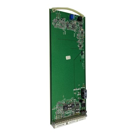
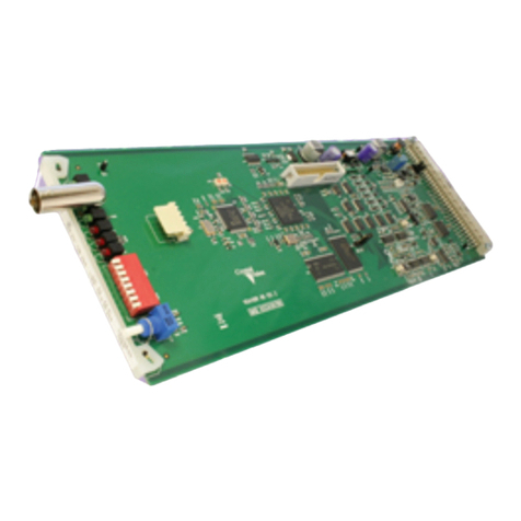
The front edge of the card provides useful power rail monitoring, in addition to card edge
controls and two headphone monitoring outputs.
AADA-STM-1 front edge view
The bottom green LED indicates good +/- 18 Volt power rails when lit and the upper
green LED indicates a good +5 Volt rail when lit.
The yellow LEDs illuminate to indicate either an output overvoltage error or channel
silence error. The top left-hand yellow LED is for output group 1, the lower left-hand
yellow LED is for output group 2. Similarly, the top right-hand yellow LED is for output
group 3 and the bottom right-hand yellow LED is for output group 4.
Overvoltage LED indication may be inhibited by changing the position of a jumper link,
as explained in the configuration section of the Installation chapter.
The headphone outputs are a useful way of checking the presence and quality of audio at
the output of the quad amplifier after all the gain adjustments and channel combining.
Take care when using headphone monitoring that high signal levels are not present.
Basic fault finding guide
The Power OK LEDs are not illuminated
Check that the frame PSU is functioning – refer to the appropriate frame manual for detailed
information
Check that the card is seated correctly in the frame
Check that valid audio inputs are present and that any cabling is intact
Check that the inputs and output(s) used are valid for the combining link positions in use
Check that the output gain jumper links are fitted correctly
The gain range is not as expected
The gain range and maximum output level are dependent on the position of the jumper links as
explained in the Installation chapter
Check that the output gain jumper links are fitted correctly
The card no longer responds to card edge control
Check that the card is seated correctly and that the Power OK LEDs are lit. If necessary re-set the card
Is it safe to ground either the positive or negative audio output for unbalanced operation?
Yes. This is safe. Beware to avoid output clipping when using unbalanced output connections. This is
because connecting one phase to ground increases the level on the other phase by +6dB
To avoid damage to driver outputs, do not connect both phases to ground
If required, the card may be reset by simply removing the card from the rack and then re-inserting
It is safe to re-insert the card whilst the rack is powered
AADA-STM-1 User Manual R1.215 22 May 2018