Etabeta electronics PA-6000RM User manual

1 / 7
INSTALLATION AND OPERATION MANUAL
PA-6000RM & PA-6000SV
MATRIX SYSTEM
MICROPHONE AND PANEL MANUAal
Caution: Please read this manual carefully before operating
Damage caused by misuse is not covered by the warranty

2 / 7
About this Manual
Dear user:
Thank you for choose CMX product, before use PA-6000RM & PA-6000SV, please read the attached user
manual, so you can know how to user our device. Please keep the user manual safety so you can check it
again if any questions during the operation.
Purpose
Offer help to Install, config and operate this PA-6000RM & PA-6000SV
Target people
PA-6000RM & PA-6000SV user or installation.

3 / 7
Address setting diagram (4 is to detect the termination resistance)
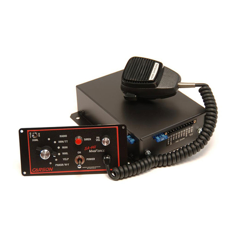
PA-6000SV 6X6 matrix multimedia power amplifier control wall controller front and rear panel diagram

4 / 7
7. Terminal block (connected to the host output network cable AUDIO-)
Connection and setup
1. The matrix amplifier has 5 input channels and a complete multi-source audio player.
2. Microphone inputs 1, 2 and 3 are designed for microphone or line-level sources such as CD or MP3 players
or mixer outputs. through the combo connector on the rear panel they can be switched via DIP switches
3. Can accept XLR plug or 6.3mm balanced or unbalanced signal.
4. Support up to 6 paging microphones or up to 6 wall control panels or no more than 6 microphone + panels.
5. The connection setting needs address matching. Please refer to the rear panel or bottom box of the device

5 / 7
for adjustment by DIP switch.
Switch the sound source through the front panel button adjustment of the main unit or the touch panel button
of the wall control panel.
DIP switch
1. Mic /Line Input 1, 2 and 3 each has 2 DIP switches Set in the rear panel and activate the +48V phantom
power condenser microphone.
2. Set the correct level for the connected input source (MIC or row).
3. If the connected source is a condenser microphone that requires phantom power, please make sure the
channel of phantom is on.
4. Make sure to turn off these DIP switches when setting up the amplifier. Any changes on the amplifier's
power supply can cause a loud noise through the system, which can damage the speaker.
5. The paging microphone and wall control panel DIP switches are used to configure the address to prevent
conflicts.
6.
The paging microphone (PA-6000RM) speaks to the first partition.
7.
1. Press Z1 of the paging microphone (PA-6000RM), the paging indicator will light up, and the digital
display of the host will display C0; press the green CALL button to start talking.
2. If you need to speak in the whole area, you can press the ALL button to quickly select, then press the
CALL button to start speaking. The main panel LEDs all display C0.
3. If the paging microphone (PA-6000RM) control is invalid, please check whether the DIP address
switch dial code on the rear panel is correct, whether it matches, and whether there is a conflict.
4.Third, the control panel (PA-6000SV) use
1. If you need to use the control panel (PA-6000SV) to select the source, use the control panel channel
plus or minus keys to adjust the desired source.
2. If you need to play Bluetooth separately, press the Bluetooth switch button, the panel displays C7,
and the Bluetooth device can play Bluetooth audio. The volume up and down buttons adjust the volume.
3. If the control panel (PA-6000SV) is not displayed, check if the cable is connected correctly. For the
corresponding connection method, please refer to the description of the upper right corner of the rear
panel network port and the control panel (PA-6000SV) bottom box.
4. If the control panel (PA-6000SV) control is invalid, please check whether the DIP address switch
dialing of the rear control panel (PA-6000SV) is correct, whether it matches, and whether there is a
conflict.

6 / 7
Note: Bluetooth connection, initially no password.
1. Balanced audio input 100V/70V speaker unbalanced audio input 8 Ohms
Attention
1) Do not install the system equipment in direct sunlight or near the heating element, because the
device may be deformed, faded or due to high temperature into the protection state and stop
working;
2) Do not install the system equipment or stored in dusty, humid place, otherwise it will cause the
stability of the system equipment or intermittent failure;
3) To prevent the equipment was affected from the high electromagnetic, the equipment should be as
far away from the strong magnetic field equipment as possible.
SERVICE
Ensure the problem is not related to operator error, or system devices that are external to this unit.
Information provided in the troubleshooting portion of this manual may help with this process. Once it is
certain that the problem is related to the product contact your warranty provider as described in the
warranty section of this manual.
WARRANTY
Warranty terms of global three years. While the term and warranty may vary by country and may not be the
same for all products. Terms and conditions of warranty for a given product may be determined first by
locating the appropriate country which the product was purchased in, then by locating the product type.
This manual suits for next models
1
Table of contents
