CS Instruments 0530.0106 User manual
En- English
Parabolic mirror V1.00 EN Page 1from 11
Instruction manual
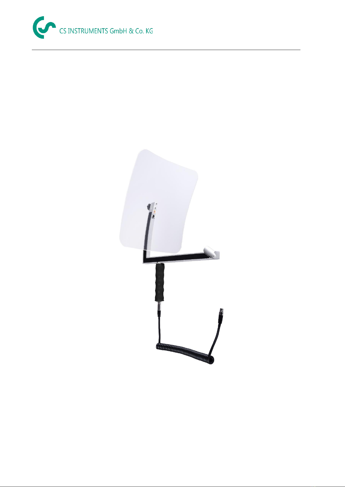
Parabolic mirror

Table of contents
Parabolic mirror V1.00 EN Page 2from 11
1Table of contents
1TABLE OF CONTENTS ...............................................................................................................................................2
2SAFETY INSTRUCTIONS ............................................................................................................................................3
2.1 GENERAL SAFETY INSTRUCTIONS .........................................................................................................................................3
2.2 HANDLING CLASS 2LASER .................................................................................................................................................3
3SERVICE AND MAINTENANCE ..................................................................................................................................4
4PROTECT ENVIRONMENT ........................................................................................................................................4
5INTENDED USE.........................................................................................................................................................4
6TECHNICAL DATA OF THE PARABOLIC MIRROR........................................................................................................4
7IDENTIFICATION ......................................................................................................................................................5
7.1 NAMEPLATE ...................................................................................................................................................................5
7.2 LASER WARNING LABEL .....................................................................................................................................................5
7.3 LABEL POSITIONING PARABOLIC MIRROR...............................................................................................................................6
8USE OF THE PARABOLIC MIRROR.............................................................................................................................6
8.1 MECHANICAL CONNECTION TO THE LD 5X0 VIA THE SPIRAL CABLE ............................................................................................6
8.2 AUTO TOOL RECOGNITION ................................................................................................................................................7
8.3 IMPORT OF THE NEW TOOL................................................................................................................................................7
8.4 AUTOMATIC DISTANCE MEASUREMENT ................................................................................................................................8
8.5 DESCRIPTION -FUNCTIONALITY ..........................................................................................................................................8
States.............................................................................................................................................................................10
Safety instructions
Parabolic mirror V1.00 EN Page 3from 11
2Safety instructions
About this document
•Read this documentation carefully and familiarize yourself with the product
before using it. Pay particular attention to the safety instructions and warnings to
prevent injuries and product damage.
•Keep this documentation handy for reference when needed.
•Pass this documentation on to subsequent users of the product.
2.1 General safety instructions
•Only use the product properly and for its intended purpose and within the
parameters specified in the technical data. Do not use force.
•Never measure with the device on or near live parts!
During the inspection of electrical systems, please keep a sufficient safety
distance to avoid dangerous electric shocks!
•Avoid any direct contact with hot -, rotating parts.
•Always switch on the device before putting on the headphones! If the signal
levels are high (bar graph headphones in the red area), the volume can also be
correspondingly high. Use the arrow keys to reduce the volume.
•Observe the specified storage and operating temperatures.
•Improper handling or use of force will void the warranty.
•Tampering with the device in any way, unless it is in accordance with the
intended and described procedures, will void the warranty and exclude liability.
•The device is intended exclusively for the purpose described.
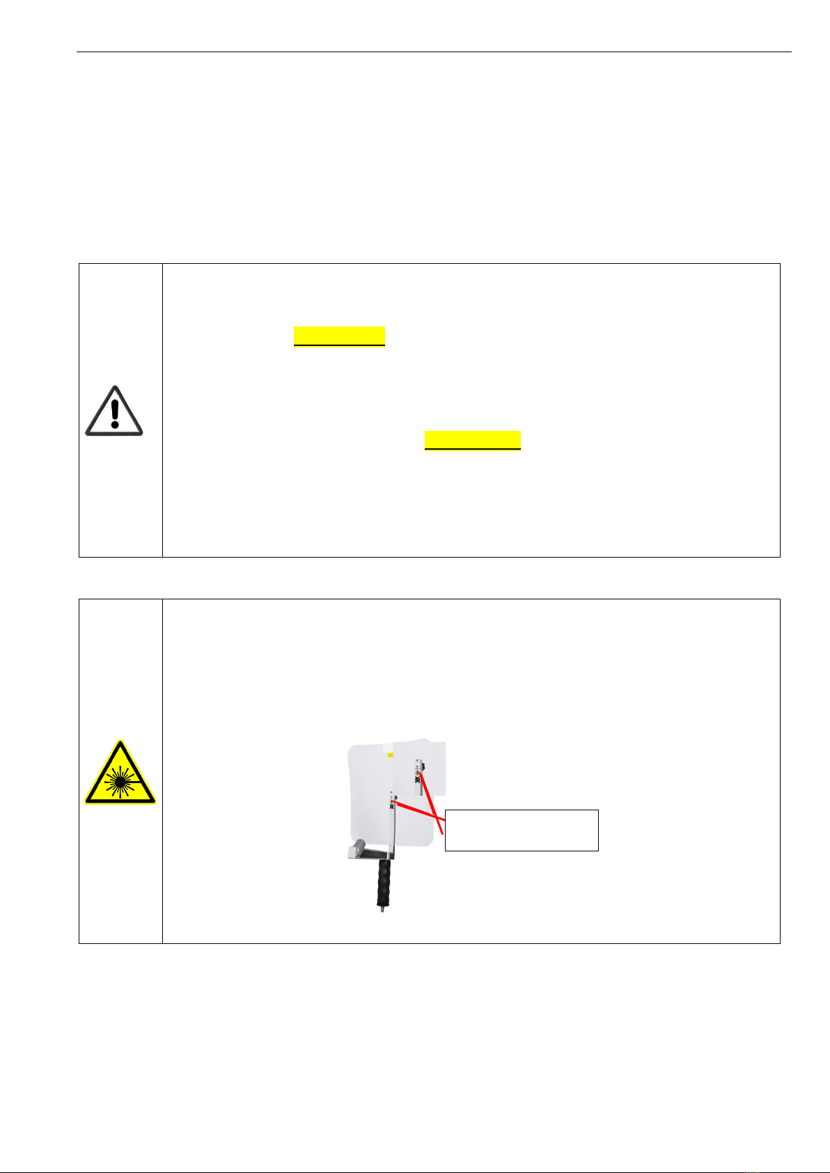
2.2 Handling class 2 laser
•Never point the integrated laser directly at people!
•Avoid direct irradiation of the eyes of humans and animals at all costs!
•If Class 2 laser radiation hits the eye, consciously close the eyes and immediately
move the head out of the beam.
•Do not look into the direct or reflected beam.
•Laser output point of the parabolic mirrors:
Laser output point

Technical data LD500
Parabolic mirror V1.00 EN Page 4from 11
3Service and maintenance
Service and maintenance work may only be carried out by authorized personnel.
4Protect environment
•At the end of its service life, take the product to separate collection for electrical and electronic
equipment (observe local regulations) or return the product to CS INSTRUMENTS GmbH &
Co.KG for disposal.
•CS INSTRUMENTS GmbH & Co.KG makes no warranty as to the suitability for any particular
purpose and assumes no liability for errors printed in these operating instructions. Nor for
consequential damages in connection with the delivery, performance or use of this device.
5Intended use
The LD 500 is a leak detector for fast and reliable leak detection in/on compressed air systems. The LD500
leak detector evaluates the ultrasonic waves generated by the leak as a function of distance and pressure.
It is designed and constructed exclusively for the intended use described here and may only be used
accordingly.
A check whether the device is suitable for the selected application must be carried out by the user. The
technical data listed in the data sheet are binding.
Improper handling or operation outside the technical specifications is not permitted. Claims of any kind
due to improper use are excluded.
§ 4 Paragraph 4 Electrical and Electronic Equipment Act
6Technical data of the parabolic mirror
Dimensions
300 mm x 460 x 270 mm
Weight
737 Gr.
Working frequency
40kHz (+/- 2kHz)
Operating time
> 9 h (continuous operation)
Laser
Wavelength 645-660nm, output power < 1mW (laser class 2)
Connections
Connector - for use of the parabolic mirror with the LD 500 / LD
510 by means of the spiral cable
Application Area
Interior
Operating temperature
-5 °C to +50 °C
Storage temperature
-20 °C to +60 °C
Altitude
Up to 4000m above sea level
Max. Humidity
<95% rH, without condensation
Pollution degree
contamination
2
General functional description
Parabolic mirror V1.00 EN Page 5from 11
7Identification
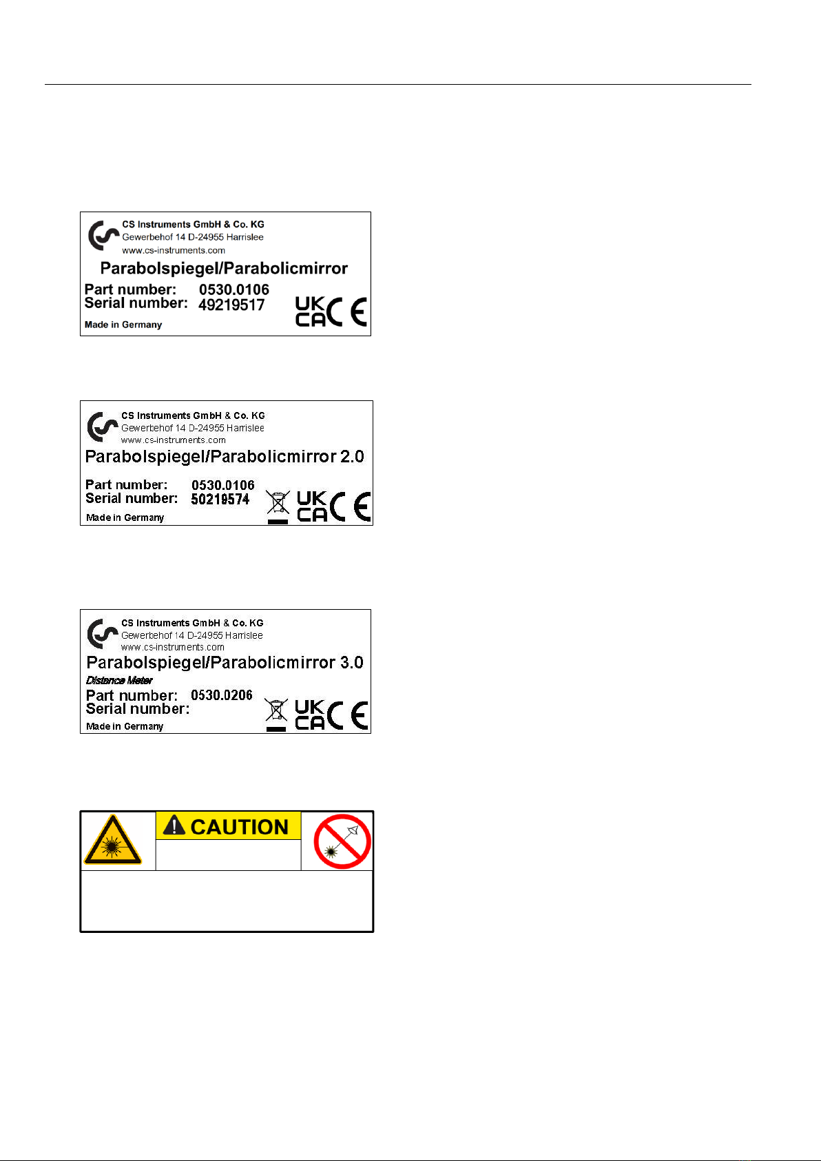
7.1 Nameplate
Parabolic mirror without automatic tool detection→see: 6.3 Importing the new attachment:
Parabolic mirror 2.0 has the Automatic detection and does NOT need to be taught.
Parabolic mirror 3.0 has the Automatic detection and does NOT need to be taught. In addition, this has a
laser distance measurement.
7.2 Laser warning label
Acccording IEC 60825-1:2014
Max. output power: <1mW @ 630-660nm
Complies with 21 CFR 1040.10 and 1040.11except for
conformance with IEC 60825-1 Ed.3., as described in
Laser Notice No. 56, dated May 8,2019
Laser 2
General functional description
Parabolic mirror V1.00 Page 6from 11
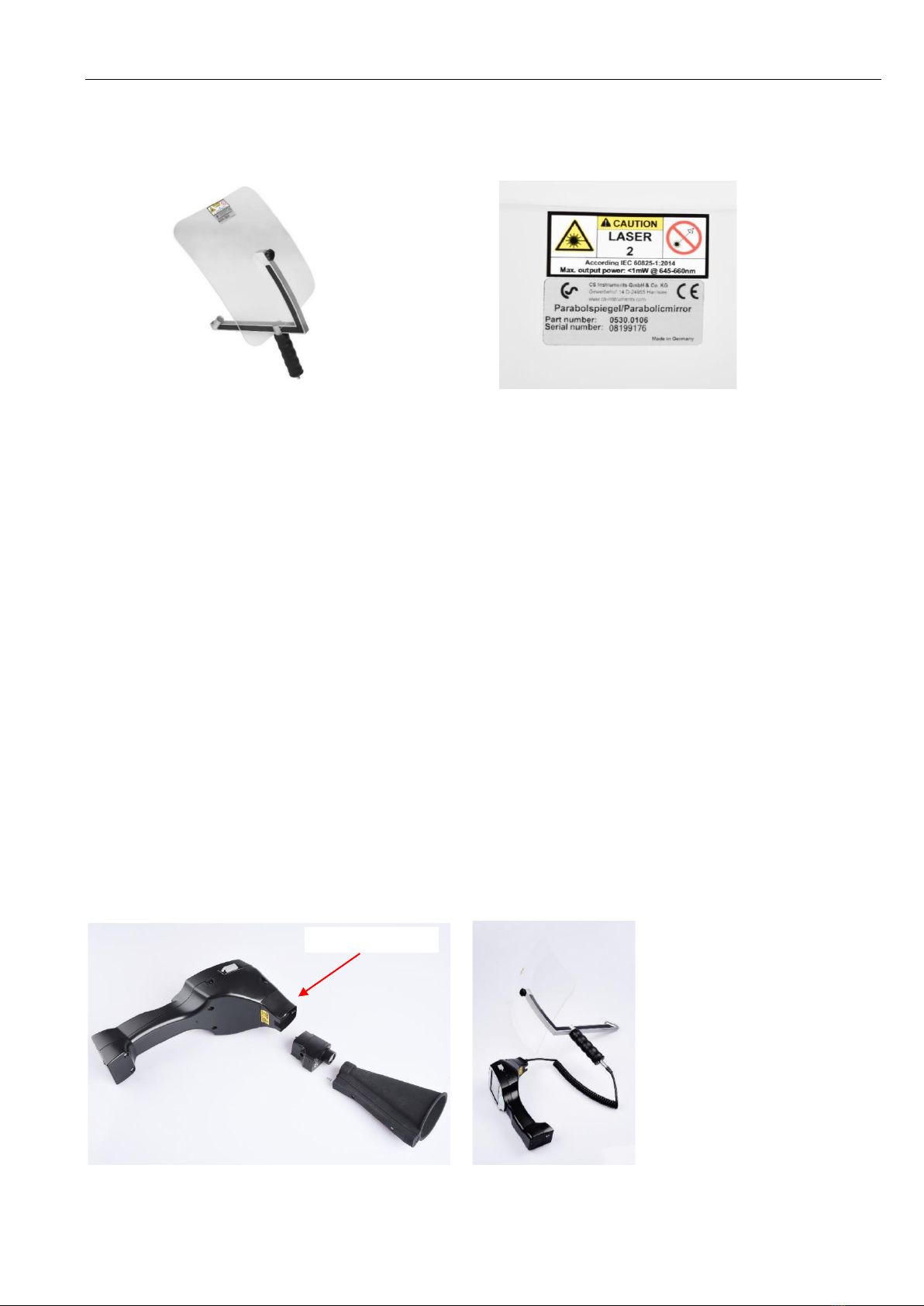
7.3 Label positioning parabolic mirror
8Use of the parabolic mirror
The parabolic mirror focuses horizontally incident ultrasound at its focal point, where the ultrasonic
transducer is located. On the one hand, this leads to a considerable amplification of the measured
ultrasound (high range) and, on the other hand, to a very precise directivity, since non-horizontally
incident ultrasound is reflected from the mirror.
The combination of these two characteristics allows the parabolic mirror to precisely locate leaks at long
distances.
Quantification distance→3 - 12 m
Use parabolic mirrors:
•High distance to the line/component 3 - 12 m
•Noise
•Leakage not freely accessible
8.1 Mechanical connection to the LD 5X0 via the spiral cable
Before the parabolic mirror can be connected by means of the spiral cable, the funnel must be removed.
Unlock button
General functional description
Parabolic mirror V1.00 Page 7from 11
Please make sure that the mirror is mounted by means of the screw according to the curve of the base
body, so that the holes in the mirror sit above the camera and the laser.
The parabolic mirror is removed by disconnecting the connection cable. To do this, press the release
button on both sides and pull off the cable.
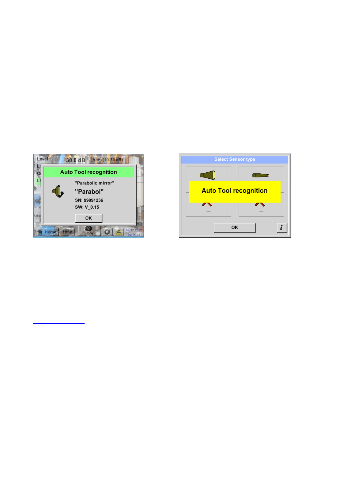
8.2 Auto Tool Recognition
If a parabolic mirror V2 or a parabolic mirror V3.0 with laser distance measurement is connected to an
intelligent LD 500 / LD 510, it is automatically detected.
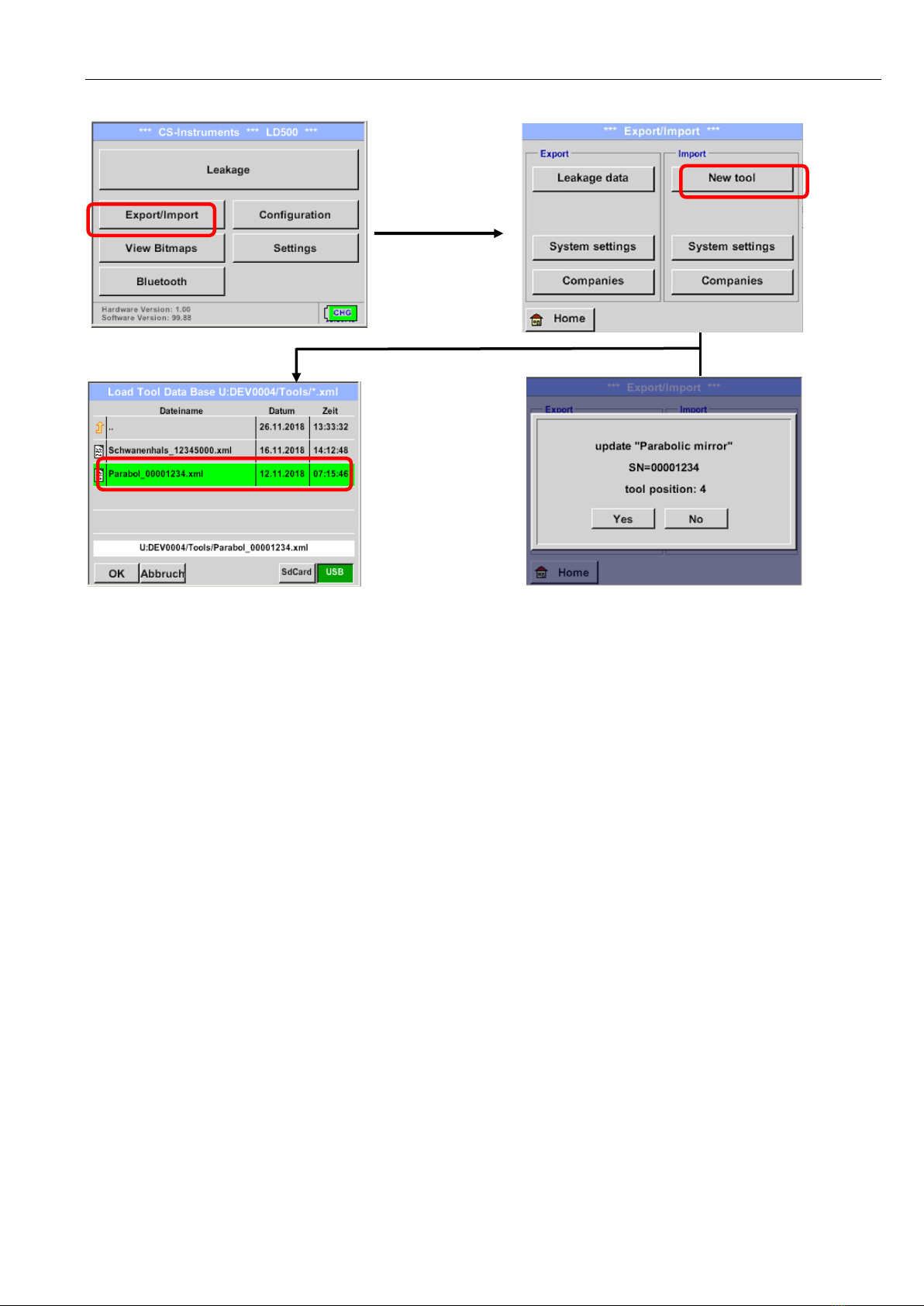
8.3 Import of the new Tool
If you use a parabolic mirror V1.0 or the parabolic mirror was reordered and the LD 500 has an
"intelligence" - the application data for the parabolic mirror must first be loaded into the LD500.
The XML file for the tool import is delivered via USB stick and is stored in the directory
\DEV0004/Tools/ as XML file.
The tools are integrated via the "Import new Tool" menu.
•Home→Export/Import→"Import new Tool".
•Selection of the "USB" storage location
•Depending on the tool, one of the following files must be selected
➔Parabol_xxxxxx.xml
➔Gooseneck_xxxxxx.xml
•Confirm with "OK" and then with "Yes".
General functional description
Parabolic mirror V1.00 Page 8from 11
Import:
Home→ Export/Import → Import new Tool → Parabolic mirror/gooseneck serial number
8.4 Automatic distance measurement
The new parabolic mirror is equipped with an integrated distance measurement module. To use the
functionalities, the following requirements must be met:
-The main board must be "intelligent" to allow communication between the main body of the LD
500 and the tool.
-The firmware of the LD 500 must be at least V3.02.
If these requirements are met, the LD 500 automatically detects that a tool with automatic distance
measurement is connected.
Description - Functionality
oTo activate the distance measurement, the laser must be started, as with all other tools.
oThe LD 500 then shows the measured distance on the display.
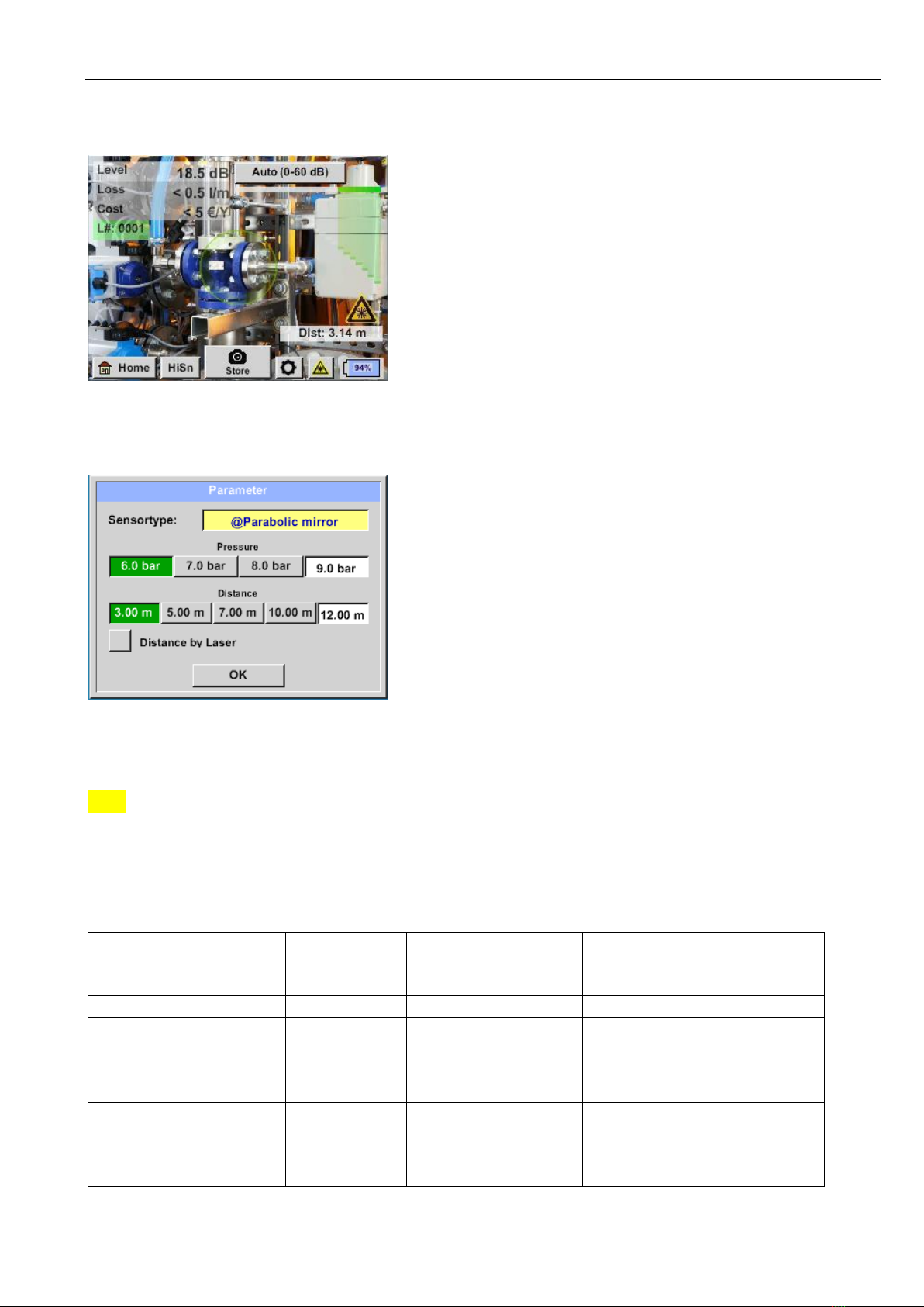
8.5 Description - Functionality
oThe laser must be started as with all other tools to activate the distance measurement.
oThe LD 500 then shows the measured distance on the display. In this case, it is 3.14
meters or 124".
General functional description
Parabolic mirror V1.00 Page 9from 11
To use the measured distance for cost quantification, "Distance by laser" must be activated under
"Parameters".
Note: Before "Distance by laser" can be activated, the laser must be switched on. Otherwise, the symbol
flashes yellow and red.
Note: For the parabolic mirror, the valid distance range is 3 - 12 meters or 118.11" - 472.441".
The LD 500 now automatically updates the distance. The current measured distance is displayed in the
gray bar "Dist:". The distance used for costing is displayed in the small bar at the bottom left of the
print.
State
Current
distance
measurement
Used distance
Parameter
internal:
Probability that the
distance is measured correctly
Best case
White
Green
High
Assess plausibility of the
measurement
Yellow
Yellow
Medium
Move to the valid
distance range
White
Yellow
High, but distance outside the
valid range
Aim at another surface
near the leak until "Best
case" occurs and the
measurement is robust
Red
Empty
Low:

General functional description
Parabolic mirror V1.00 Page 10 from 11
Attention: On black surfaces or in very bright environments, measuring the distance can be problematic.
Therefore, it is still possible to enter distances manually. "Distance by laser" must be deactivated, then
manual distances can be entered.
States :
"Dist:" is green, the distance module measurement is
robust, and the distance used is in the valid range.
Out of range:
Distance measurement = robust, but out of range!
➔Please move within the valid distance range!

General functional description
Parabolic mirror V1.00 EN Page 11 from 11
OFFICE NORTH
Gewerbehof 14
D-24955 Harrislee
GERMANY
Tel.: +49 (0) 461 80 71 50 - 0
Fax: +49 (0) 461 80 71 50 - 15
info@cs-instruments.com
www.cs-instruments.de
OFFICE SOUTH
Zindelsteiner Straße 15
D-78052 VS-Tannheim
GERMANY
Tel.: +49 (0) 7705 978 99-0
Fax: +49 (0) 7705 978 99-20
info@cs-instruments.com
www.cs-instruments.de
This manual suits for next models
3
Table of contents
Popular Indoor Furnishing manuals by other brands


WTZ Bamboo Home
WTZ Bamboo Home Ladder Bookshelf installation manual

Canadel
Canadel QUI2SACZ067 Assembly instructions

SUNPAN
SUNPAN Quinn 100766 Assembly instruction sheet

Simple By Design
Simple By Design 73SDRST02 Assembly instructions

Franklin & Ben
Franklin & Ben BECKETT RUSTIC M24401 manual

Astonica
Astonica 50105364 instruction manual