CSE BIOMARINE BIOPAK 240-R User manual

BioPak 240R
Closed-Circuit, Self-Contained Breathing Apparatus
Benchman Manual
1437

BioPak 240R Benchman Manual
A47D257, Revision M
June 2023
2
WARNINGS 4
1. INTRODUCTION 5
1.1 Breathable Oxygen 5
1.2 Apparatus Duration 5
1.3 Personnel Training 5
1.4 Servicing 5
1.5 Spare Parts 6
2. APPARATUS DESCRIPTION 7
2.1 General 7
Approval/Conforming Standards 7
Notified Bodies 7
2.2 Harness 8
2.3 Housing 8
2.4 Breathing Loop 8
2.5 Oxygen Delivery System 8
2.6 Oxygen Cylinder 8
2.7 Alarming System 8
2.8 Facemask 9
2.9 Optional Attachments 9
3. TURN AROUND MAINTENANCE PROCEDURE 10
3.1 Maintenance Tag 10
3.2 Disassembly 10
3.3 Cleaning/Disinfection 10
3.4 Coolant Canister 11
3.5 Oxygen Cylinder 11
3.6 Facemasks 11
3.7 Assembly 12
3.8 Constant Flow Test 12
3.9 Low Pressure Leak Test 13
3.10 Alarm Test 13
3.11 Upper Housing 14
3.12 Carbon Dioxide Scrubber Pre-Packing Procedure 14
4. LONG TERM MAINTENANCE PROCEDURE 16
4.1 Visual Inspection 16
4.2 Demand Valve Functional Test 16
4.3 Constant Flow Test 16
4.4 Vent Valve Functional Test 16
4.5 Low Pressure Leak Test 16
4.6 High Pressure Leak Test 16
4.7 Emergency Bypass Valve Functional Test 17
4.8 Alarm Test 17
4.9 Maintenance Tag Validation 17
5. GENERAL SERVICE PROCEDURES 18
5.1 Scheduled Component Inspection 18
5.2 System Lubrication 18
5.3 Oxygen Cylinder 18
5.4 Alarm Battery Replacement Procedure 19
5.5 Flow Restrictor Replacement Procedure 19
5.6 Factory Service and Training 20
6. STORAGE GUIDELINES 20

BioPak 240R Benchman Manual
A47D257, Revision M
June 2023
3
7. PARTS LISTS 21
7.1 Top Assembly 21
7.2 PRO PP Facemask Assembly 24
7.3 PRO Breathing Hose 25
7.4 Center Section Lid 26
7.5 Center Section 27
7.6 Diaphragm 29
7.7 Pneumatic Assembly 30
7.8 Manifold Assembly 32
7.9 Alarm Monitor 33
7.10 Oxygen Cylinder (flat seal outlet type) 34
7.11 Oxygen Cylinder (o-ring seal outlet type) 35
7.12 Lower Housing 36
7.13 Ice Canister Freeze Form 39
7.14 Service Kit 41
7.15 Miscellaneous Supplies 42
7.16 Optional Attachments 42
8. APPARATUS SPECIFICATIONS 43
9. MAINTENACE LOG SHEET 44
APPENDIX A: O-RING & SEAL INSPECTION/LUBRICATION GUIDE 45
DECLARATION OF CONFORMITY 46

BioPak 240R Benchman Manual
A47D257, Revision M
June 2023
4
WARNINGS
Please Read Carefully and Fully Understand
This manual is for use by personnel trained in the use and care of compressed oxygen,
closed-circuit breathing apparatus, and MUST NOT be used as a self-teaching guide by
untrained users. Failure to understand or adhere to the BioPak user instructions and BioPak
benchman manual may result in injury or death.
Biomarine Inc. has taken great care to ensure that the information in the manual is accurate,
complete and clear. However, Training & Technical Support Services will be pleased to
clarify any points in the manual and answer questions on Biomarine breathing apparatus.
The following warnings are in accordance with certifying authority requirements and
apply to the use of breathing apparatus in general:
•Breathing apparatus user must be fully trained in the use and care of closed-
circuit, self-contained, compressed oxygen breathing apparatus.
•Ensure that the selection of the apparatus type is sufficient for the tasks being
undertaken and the hazards likely to be encountered. Please refer to National
Regulations for guidance.
•Adequate protection may not be provided in certain highly toxic atmospheres.
•The apparatus must be tested and serviced in accordance with the BioPak 240R
Benchman Manual.
•The quality of oxygen used to supply and charge the breathing apparatus must
be medical or aviation grade oxygen with a moisture content less than 50 mg/m3
at 207 bar.
•Ensure that a good seal can be obtained between the face and facemask. The
wearing of beards, side-burns or spectacles may adversely affect the sealing of
a facemask to the wearer’s face.
•The apparatus is not designed for use as an underwater diving rebreather.
•The harness must not be used as a vehicle seat or fall arrest restraint.
•Replacement of the alarm system battery shall be performed in area
atmospheres known to be safe and non-explosive.
•The improper use of closed-circuit breathing apparatus carries a risk of carbon
dioxide poisoning of user. Users shall be fully trained in recognizing the effects
of carbon dioxide poisoning.
•Carbon Dioxide Scrubbers must be stored at a temperature between 4oC and
32oC to prevent degradation of the absorbent material.
•Carbon Dioxide Scrubbers must be utilized with the supplied Moisture Pad to
prevent scrubber canister flooding that may lead to elevated carbon dioxide
levels in the breathing gas.
DISCLAIMER
Failure to comply with these instructions or misuse of the apparatus may result in:
death, injury or material damage, and invalidate any warranty or insurance claims.
This manual presents the minimum requirements for BioPak utilization.

BioPak 240R Benchman Manual
A47D257, Revision M
June 2023
5
1. INTRODUCTION
1.1 Breathable Oxygen
Oxygen used to supply or charge the
breathing apparatus must be medical or
aviation grade oxygen with moisture
content less than 50 mg/m3at 207 bar.
The composition of suitable oxygen is
given below and provides the maximum
level of contaminates in the source oxygen
acceptable for use in the BioPak.
Oxygen: 99.5% minimum mole
Carbon Dioxide: 300 ppm maximum
Carbon Monoxide: 10 ppm maximum
The purity/quality of oxygen used to supply
and charge breathing apparatus should be
tested periodically in accordance with
national regulations.
National regulations must be observed.
Personnel dealing with compressed
oxygen and compressed oxygen cylinders
must be fully trained in the use and
handling of compressed oxygen.
1.2 Apparatus Duration
The apparatus will provide the user with
440 liters of compressed oxygen and has
been rated for a 4-hour duration based
upon machine testing at a breathing rate
of 30 liters/minute according to
specifications of EN145. Actual duration
of the apparatus will vary due to factors
such as:
•Workload: high work rates will
increase consumption rates of
oxygen.
•Facemask Seal: poor seal of mask
will result in system leaks and high
oxygen consumption rates.
•Physical Fitness of Wearer
•System Leaks: leaks in the BioPak
system will result in high oxygen
consumption.
It is important that all wearers are aware of
the above factors when assessing BioPak
duration.
It is equally important that all wearers
understand that the BioPak 240R
respirator is a positive-pressure apparatus.
Leaks in the apparatus itself or in the seal
between the wearer’s face and the
facemask will lead to the apparatus adding
additional oxygen to maintain positive
pressure.
1.3 Personnel Training
Personnel who use closed-circuit, self-
contained, positive-pressure, compressed
oxygen breathing apparatus must be fully
trained in accordance with these
instructions and national regulations.
These instructions cannot replace an
accredited training course provided by
qualified instructors in the proper and safe
use of Biomarine breathing apparatus.
Please contact Training & Technical
Support Services or your local distributor
for training course details.
1.4 Servicing
The BioPak 240R must be serviced at
scheduled intervals by qualified benchmen
personnel who have completed a formal
training course and hold a current
certificate for the service and repair of
Biomarine breathing apparatus.
Turn Around Maintenance shall be
performed after each use of the BioPak
240R as detailed in the BioPak 240R
Benchman Manual.
Long Term Maintenance must be
performed on a monthly basis, if the
BioPak is in constant use; or, on a
quarterly basis if the BioPak is being used
less than once per month, as defined in
the BioPak 240R Benchman Manual.
Benchman training and service contracts
can be provided by contacting Training &
Technical Support Services.

BioPak 240R Benchman Manual
A47D257, Revision M
June 2023
6
1.5 Spare Parts
Spare parts, accessories, general
information and factory service can be
obtained by contacting Training &
Technical Support Services.
Reference details are provided in the
BioPak 240R Benchman Manual
concerning spare part identification,
accessory identification and BioPak
factory service.
Manufacturer info, Training & Technical
Support Services, and Declaration of
Conformity:
Biomarine Inc.
A Wholly Owned Subsidiary of CSE
Corporation
1001 Corporate Lane, Suite 240
Export, PA 15632
United States of America
Tel: +1 412.856.9200
Fax: +1 412.856.9203
Web: Biomarineinc.com
•Customers can also contact their
local authorized Biomarine
Distributor for training, product
support, emergency support or
maintenance.
•The BioPak 240R- User and
Benchman manuals can be
provided in electronic format upon
request.
•Reference documentation
supplied with sales order for
standard terms of warranty.
•Training posters, manuals, MSDS
data and other training materials
are available for download from
the Biomarine website.

BioPak 240R Benchman Manual
A47D257, Revision M
June 2023
7
2. APPARATUS DESCRIPTION
2.1 General
BioPak 240R is a closed-circuit, positive-
pressure, self-contained breathing
apparatus (CCBA) for use in long-duration
missions into atmospheres that are
immediately dangerous to life and health
(IDLH). The BioPak 240R is designed to
provide respiratory protection ((EU)
2016/425 Annex II, 3.10.1) protecting
against hazardous substances and
mixtures and/or insufficient oxygen
atmosphere as outlined in category III of
Annex I of (EU) 2016/425 and meets the
requirements of EN 145 for 4P/O2
protection. Applications include mine
rescue, fire-fighting, confined space entry,
domestic preparedness, military, tunnel
rescue and HAZMAT.
All versions of the BioPak 240R feature a
backpack-style housing that is worn over
the shoulders and hips of the wearer. A
pressure gauge is supplied to indicate
remaining stores of oxygen and two visual
alarms and one audible alarm is provided
for system status.
The closed-circuit design will recycle the
wear’s exhalation breath by removing
carbon dioxide, replacing consumed
oxygen, trapping condensation and
cooling the breathing gas.
The positive-pressure design will maintain
internal breathing gas pressures slightly
above external atmospheric pressure.
This feature will provide increased
protection against the inward migration of
external toxins to the wearer.
All external housing components are static
dissipative and flame retardant.
BioPak 240R is approved and conforms to
the following European Standards:
•EN 136:1998 Respiratory Protective
Devices - Full Face Masks
•EN 145:1997 Respiratory Protective
Devices – Self-contained, Closed-
circuit Breathing Apparatus
Compressed Oxygen Type
•Directive 2014/68/EU Pressure
Equipment
•EN 60079-0:2018 Explosive
Atmospheres-Equipment General
Requirements
•EN 60079-11:2023 Explosive
Atmospheres-Equipment Protection
by Intrinsic Safety “I”
•EN 60079-26:2021 Explosive
Atmospheres. Equipment with
Equipment Protection Level (EPL) Ga
•EN 50303:2000 Group 1, Category
M1 Equipment Intended to Remain
Functional in Atmospheres
Endangered by Firedamp and/or
Coal Dust
•IEC 60079-0:2018 Edition:7.0
Explosive Atmospheres – Part 0:
General Requirements
•IEC 60079-11:2023 Edition:7.0
Explosive atmospheres – Part 11:
Equipment Protection by Intrinsic
Safety “I”
•2014/34/EU ATEX Directive
BioPak 240R is “CE” marked in
accordance with Regulation (EU)
2016/425 of the European Parliament and
of the Council of 9 March 2016 on
Personal Protective Equipment
BioPak 240R Facemask is “CE” marked
in accordance with EC type examination
EC/S/2912/2018.
BioPak 240R Monitor is marked
NOTIFIED BODIES:
Central Institute for Labour Protection –
National Research Institute
(Notified Body No. 1437)
Wierzbowa 48
90-133 Lodz, Poland
Intertek Italia SpA
Via Miglioli 2/A
20063 Cernusco sul Naviglio
Milano, Italy
TÜV SÜD Industrie Service GmbH NB
Notified Body No. 0036
Please contact Biomarine Inc.for further
apparatus approval details.
BioPak 240R Benchman Manual
A47D257, Revision M
June 2023
8
2.2 Harness
The flame-retardant BioPak harness is
padded to increase wearer comfort and is
manufactured from Kevlar™ and Nomex™
materials.
2.3 Housing
The backpack-style housing is constructed
of flame-retardant polycarbonate/stainless
steel alloy that provides lightweight, high
strength and static dissipation. The
housing consists of a lower portion and an
upper portion that snaps together in a
secure fashion without the need for
connection hardware.
2.4 Breathing Loop
The breathing loop consists of the
breathing chamber, breathing hoses,
facemask connector and facemask.
The breathing chamber consists of the
center section, center section lid and
diaphragm. The spring loaded diaphragm
will maintain positive pressure within the
apparatus. All oxygen gas additions will
occur within the breathing chamber as well
as over pressure venting. Carbon dioxide
is removed from exhalation gas by the
carbon dioxide scrubbers located within
the breathing chamber. Excessive
moisture will be retained by the moisture
containment sponges located within the
center section. Inhalation breathing gas
cooling will be achieved as the gas travels
around the two coolant canisters of the
breathing chamber.
2.5 Oxygen Delivery System
Oxygen will be delivered from the oxygen
cylinder to the breathing loop through a
pressure regulator and manifold system in
one of three different methods.
Pressure demand oxygen additions are
provided whenever the diaphragm of the
breathing chamber reaches the upper
level of its travel and depresses the
demand valve plunger. Additions will be
made at 80 liters/minutes whenever the
demand valve plunger is depressed.
Pressure demand additions occur
whenever the wearer consumes more
oxygen than is supplied by the constant
add.
Constant add oxygen additions are
continually added to the breathing loop at
an average rate of 1.8 liters/minute. This
oxygen addition rate is equivalent to the
oxygen consumption rate of a wearer at a
moderate work rate.
Emergency add oxygen additions occur
whenever the wearer depresses and holds
the red emergency bypass button. This
add will provide 80-100 liters/minute of
oxygen flow and is utilized only for
emergency situations.
2.6 Oxygen Cylinder
The oxygen cylinder is a fully wrapped
aluminum carbon fibre composite cylinder
that is secured into the apparatus via
connection to the pressure regulator and a
hold down strap. The cylinder will provide
containment of the oxygen supply at a 207
bar to provide 440 liters of breathable
oxygen to the wearer.
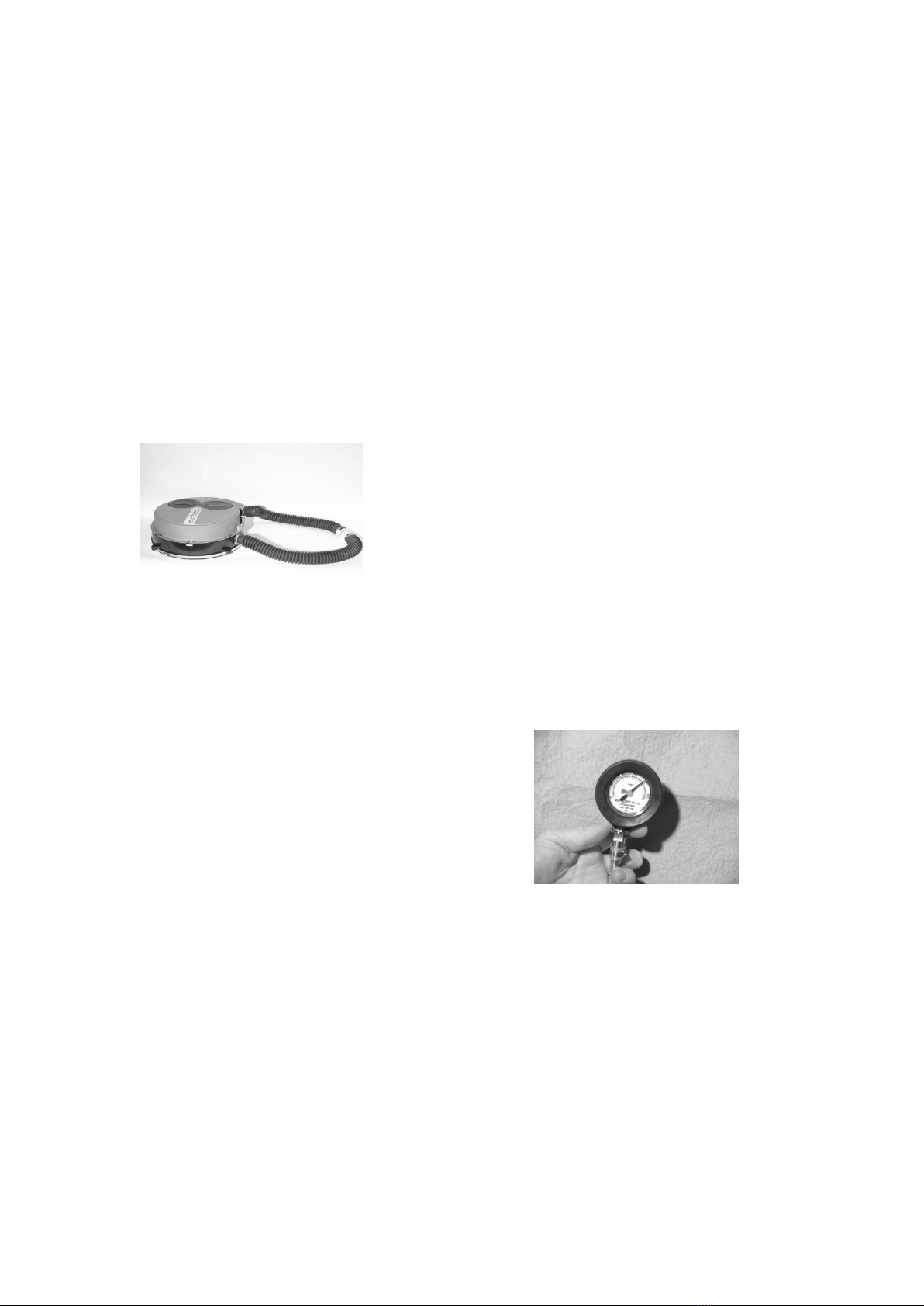
2.7 Alarming System
The alarming system consists of a
pneumatic pressure gauge and an
electronic monitor to provide the wearer
with independent and redundant system
status indications.
The pressure gauge is mounted on the
harness and retained by a snap strap.
Remaining stores of oxygen will be
indicated on the gauge and a red band of
color will indicate to the wearer when
oxygen stores have reached 25% of
capacity. The pressure gauge is protected
against sudden loss of oxygen stores in
the event of gauge line severing by a
manual disconnect located at the gauge
pass through point of the housing.
The electronic monitor will provide the
wearer indications of system status as
listed below through the LED located on
the pneumatic pressure gauge and via an
BioPak 240R Benchman Manual
A47D257, Revision M
June 2023
9
alarm horn located on the monitor
package.
Condition Alarm Action
System Ok Flashing Green
System Fault Flashing Red
Horn Sounding
End of Service Life Flashing Red
Horn Sounding
Ice Reminder Flashing Blue
Low Battery Flash Red,
Green, Blue
Horn Sounding
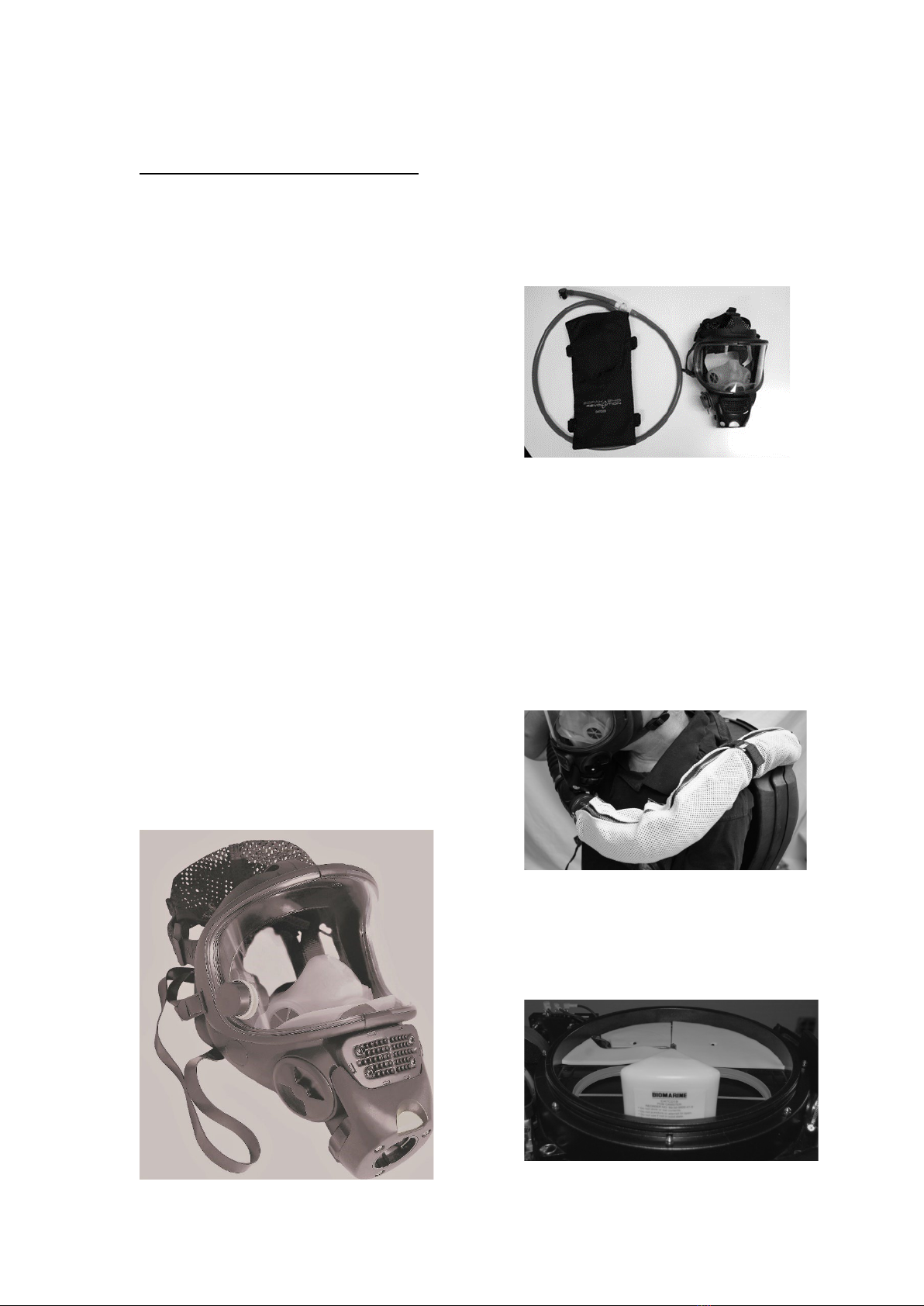
2.8 Facemasks
BioPak 240R is approved for use with the
PRO PP full facemask, which conforms to
EN136, Class 3.
All facemasks are provided with a five-
point, fully adjustable head harnesses.
To prevent fogging during use, the internal
surface of the facemask lens is covered
with a permanent anti-fog film that will not
require the application of any anti-fog
spray or wipe.
All facemasks connect to the apparatus
via a push button, bayonet hose
connection.
Speech diaphragms are provided to allow
verbal communication and all masks are
provided with a magnetic wiper that is for
optional user utilization.
The polycarbonate visors of all facemasks
conform to EN 166, Grade B for impact
resistance.
Pro PP Mask
2.9 Optional Attachments
•Hydration systems provide the
wearer with a source of drinking
liquid without breaking the seal of the
breathing loop to the external
atmosphere.
•Kevlar™ breathing hose covers
provide additional abrasion protection
to breathing hoses.
•Radiant heat guards provide
additional breathing hose protection
against high radiant heat and direct
flame contact.
•Phase Change Module (PCM)
provides cooling to the breathing gas
when ice coolant is not utilized. Note
that the PCM is required when the
ice coolant is not utilized.
BioPak 240R Benchman Manual
A47D257, Revision M
June 2023
10
Contact Biomarine or your local
distributor for additional details and supply
of optional attachments.
3. Turn Around Maintenance
Procedure
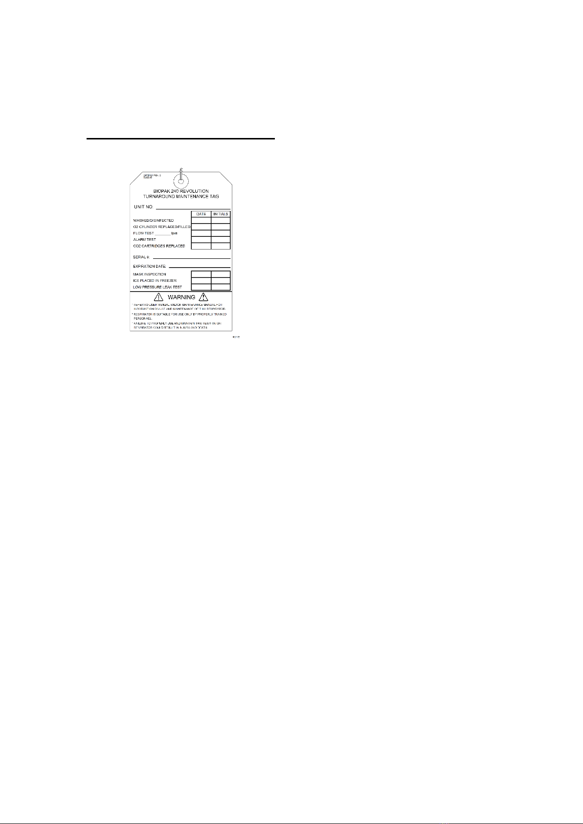
3.1 Maintenance Tag
Obtain a maintenance tag as supplied with
replacement carbon dioxide scrubbers.
The maintenance tag shall be completed
as directed in this procedure and then
attached to the apparatus in a prominent
location to show completion of all
maintenance steps.
Record the apparatus identification onto
the tag.
3.2 Disassembly
Immediately after completion of BioPak
use, remove the used CO2 scrubber
canisters, scrubber moisture pad and
disconnect the demand and constant
add lines to the center section to
prevent migration of moisture into the
manifold assembly.
Disassemble the apparatus to ready for
cleaning and disinfection. Note any
apparatus damage and repair as needed.
Repairs beyond the scope of the
Benchman should be referred to
Biomarine.
1. Remove the upper housing.
2. Remove the coolant lids and coolant
ice.
3. Remove the oxygen cylinder, making
sure the seal washer remains in place,
and install the regulator wash cover
supplied with the service kit.
It is acceptable to leave the oxygen
cylinder in place until after washing
and disinfecting has been completed to
prevent the ingress of contaminants
into the high pressure plumbing of the
BioPak.
4. Remove the facemask from the
breathing hoses.
5. Remove the breathing hoses from the
breathing chamber.
6. Remove the center section lid.
7. Remove and discard the two carbon
dioxide scrubbers and the scrubber
moisture pad.
8. Remove the moisture sponges and
the PCM if used.
9. Disconnect the electrical line and both
pneumatic connections to the center
section. Use care when handling the
center section. Avoid sharp objects
and rough surfaces that could damage
the rubber diaphragm.
10. Remove the four quarter-turn
fasteners and remove the center
section.
3.3 Cleaning/Disinfection
Use only cleaners and disinfectants that
are approved by Biomarine. Approved
cleaners are non-hazardous to the user
and breathing apparatus.
The apparatus must be cleaned and
disinfected thoroughly as soon as possible
after each use. If cleaning is not
immediately possible after use, at a
minimum remove and discard the carbon
dioxide scrubber and moisture pad,
remove the moisture control foam pads,
disconnect the constant add feed tube to
prevent migration of biological
contaminants. Temporarily store the
BioPak with the center section lid open to
prevent the growth of mold or mildew until
cleaning is possible.
DO NOT submerge the electronic
monitor housing.
DO NOT allow any fluids to contact the
input port of the pressure regulator.
Do NOT allow the mask to soak in
cleaning solutions for extended
periods. Extended soaking can cause
delamination of the anti-fog film.
BioPak 240R Benchman Manual
A47D257, Revision M
June 2023
11
1. Clean the upper and lower housings,
ice canisters and coolant lids and all
connected components with a mild
soap and water mixture if necessary.
2. Mix the disinfectant with clean water
as directed on the package.
3. Submerge the facemask, hoses with
facemask connector, center section
lid, center section, PCM and moisture
sponges into the disinfectant solution.
Allow the components to be wetted on
all surfaces as directed by the
disinfectant instructions. Allow the
components to be wetted on all
surfaces for a minimum of 10 minutes.
Install a Demand Port Wash Plug,
supplied with the service kit, to the
demand port of the center section to
keep water from migrating in the
demand housing.
4. Thoroughly rinse all components in
clean water to remove all disinfection
solution. It is extremely important to
fully rinse the facemask of all
cleaning solution.
5. Allow all components to dry either by
air-drying, heated drying or through
the use of a dryer system. Heat
assisted drying temperatures shall not
exceed 50oC.
6. Date and initial the maintenance tag
under Washed/Disinfected.
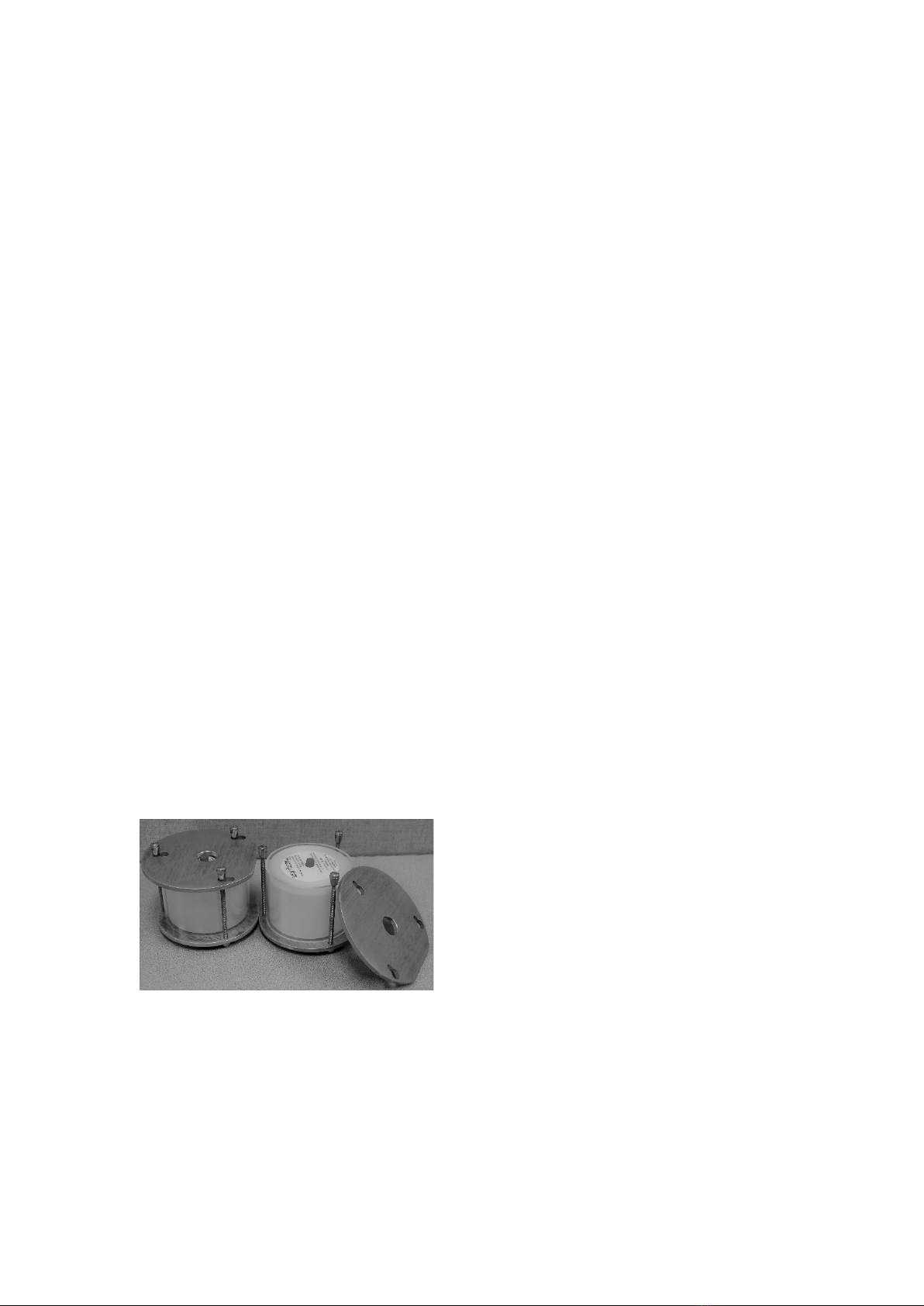
3.4 Coolant Canister
The coolant canisters must be frozen
before use.
1. Place the cleaned and dried canisters
into the freeze form and secure the lid.
2. Place the freeze forms onto a level
surface in a freezer for a minimum 8-
hour period at a temperature of -12oC
or less.
3. Date and initial the maintenance tag
under Ice Placed in Freezer.
4. If the frozen ice canisters are not
going to be utilized in the BioPak,
do not date and initial the
maintenance tag.
3.5 Oxygen Cylinder
The oxygen cylinder must be fully charged
with oxygen before use.
Oxygen used to supply or charge the
breathing apparatus must be medical or
aviation grade oxygen with moisture
content less than 50 mg/m3at 207 bar.
The composition of suitable oxygen is
given below.
Oxygen: 99.5% minimum mole
Carbon Dioxide: 300 ppm maximum
Carbon Monoxide: 10 ppm maximum
The purity/quality of oxygen used to supply
and charge the cylinder should be tested
periodically in accordance with national
regulations.
National regulations must be observed.
Oxygen will enhance the combustion of
other materials. Personnel dealing with
compressed oxygen and compressed
oxygen cylinders must be fully trained
in the use and handling of compressed
oxygen.
1. Obtain the proper cylinder fill adapter
needed to connect the oxygen cylinder
to the booster pump.
2. Connect the cylinder to the booster
pump and charge to 207 bar pressure
with medical or aviation grade oxygen.
3.6 Facemask
1. Inspect the components of the
facemask and replace as required.
2. Reinstall the magnetic wiper to
facemask if utilized.
3. Date and initial the maintenance tag
under Mask Inspection.
NOTE: The mask is supplied with a
permanent anti-fog film so no
application of anti-fog agents of any
kind are required.
BioPak 240R Benchman Manual
A47D257, Revision M
June 2023
12
3.7 Assembly
1. Position the BioPak in a level position,
as depicted above, by propping up the
handle end of the lower housing.
2. Install the center section making sure
to properly seat the three springs onto
the diaphragm.
3. Lock the center section into position
using the four quarter-turn fasteners.
4. Verify the presence of an o-ring seal
on each pneumatic line connection
and connect the electrical and
pneumatic lines to the center section.
5. Position the fully dry moisture sponges
into the center section. The sponges
must be fully dry to prevent the growth
of mold within the apparatus.
6. If utilized, install the PCM into the
breathing chamber opposite the
moisture sponges.Date and initial the
maintenance tag under Ice Placed in
Freezer and enter “PCM” on the tag.
7. Install the center section lid and latch
to secure. If pre-packing the carbon
dioxide scrubbers complete section
3.12 then return to step 7 of this
section.
8. Install the breathing hoses to the
breathing chamber and secure with
clamps making sure the flow direction
arrows of the connector are facing up.
9. Install the storage plug into the
facemask connector.
10. Install the oxygen cylinder and secure
with the hold down strap.
3.8 Constant Flow Test
1. Disconnect the constant add feed line
to the center section (green-colored
line) and connect the test flowmeter
from the service kit to the open end of
the feed line.
2. Open the oxygen cylinder valve and
observe flowmeter while holding it in a
vertical and level position. The
flowmeter shall indicate a flow as per
the table below when reading the
center of the flowmeter ball.
If the flow does not meet the requirements
of the table below, the flow restrictor will
need replacement.
Cylinder 0-5280 ft +5280 ft
Pressure, Flow, Flow,
psi lpm lpm
1500-2000 1.8-2.4 1.9-2.6
2000-3000 1.9-2.5 2.0-2.8
Cylinder 0-1600 m +1600 m
Pressure, Flow, Flow,
bar lpm lpm
100-150 1.8-2.4 1.9-2.6
150-207 1.9-2.5 2.0-2.8
3. Enter the measured flow rate, date
and initial the maintenance tag under
Flow Test____ lpm.
4. Close the oxygen cylinder valve,
remove the test flowmeter and
reconnect the constant add feed line
to the center section.
BioPak 240R Benchman Manual
A47D257, Revision M
June 2023
13
3.9 Low Pressure Leak Test
1. Remove the storage plug from the
breathing hoses and install the leak
test adapter from the service kit.
2. Attach rubber tubing from the service
kit between the leak test adapter and
the input port of the service kit.
3. Insert two test keys from the service
kit in the keyholes in the back of the
lower housing.
4. Open the oxygen cylinder valve and
depress the bypass valve until the test
kit displays a pressure just under 7
mbar (3.5” water column), then
immediately close the oxygen cylinder
valve.
5. Activate the emergency bypass valve
to empty all gas into the breathing
chamber and raise the pressure
reading to between 15 and 20 mbar (6
and 8” water column). DO NOT
overpressure.
6. After the test gauge stabilizes, note
the exact pressure reading of the
service kit and allow the apparatus to
sit undisturbed for 60-seconds. The
apparatus pressure shall not drop
more than 0.5 mbar (0.2” water
column) in the 60-second period.
If the oxygen cylinder is not closed the
pressure reading will continue to rise
and potentially damage the breathing
chamber.
If the apparatus pressure drops more
than 0.5 mbar (0.2”) in the 60-second
there is a leak that must be located and
repaired.
7. Open the service kit bleed valve
and/or remove the leak test adapter to
vent the apparatus.
8. Replace the storage plug.
9. Remove the two test keys from the
rear of the lower housing.
10. Date and initial the maintenance tag
under Low Pressure Leak Test.
3.10 Alarm Test
1. While observing the pressure gauge
and TRIM indicator, open the oxygen
cylinder valve. The cylinder must be
filled with a minimum of 100 bar (1500
psi) pressure for this test.
2. When the oxygen cylinder is opened
the TRIM indicator shall cycle RED,
GREEN, BLUE with the horn
sounding. The TRIM will then flash
GREEN and the horn will be silent.
3. The pressure gauge will reach full
reading in approximately 60-seconds.
4. Close the oxygen cylinder and allow
the BioPak to slowly reduce pressure
while observing the pressure gauge
and LED indications. The LED
indication should turn to a flashing red
with a horn sounding when the
pressure gauge reads between 45-69
(650-1000 psi)bar. The LED
indication will cease when the
pressure gauge reads under 1.7 bar
(25 psi).
5. Verify that the oxygen cylinder is fully
charged to 207 bar (3000 psi) and top
off if necessary.
6. Date and initial the maintenance tag
under O2 Cylinder Replaced/Filled.
BioPak 240R Benchman Manual
A47D257, Revision M
June 2023
14
3.11 Upper Housing
1. Replace the upper housing onto the
apparatus.
2. If the carbon dioxide scrubbers have
not been installed into the apparatus
then leave the maintenance tag CO2
Cartridges Replaced field blank.
See section 3.12 concerning
procedures for pre-packing the carbon
dioxide scrubber into the apparatus
during turn around maintenance.
3. Tie the completed maintenance tag to
the BioPak in a conspicuous and
consistent location.
3.12 Carbon Dioxide Scrubber Pre-
Packing Procedure
The Biomarine carbon dioxide scrubbers
can be pre-packed into the apparatus
during turn around maintenance if so
desired.
Pre-packed carbon dioxide scrubbers
may only be stored in the apparatus for
a maximum period of 1-year.
Moisture sponges must be installed dry
when pre-packing the BioPak.
DO NOT pre-pack any BioPak that will
be stored at temperatures at or below
freezing (32oF/0oC).
Apparatus that are pre-packed with the
carbon dioxide scrubber shall be
stored within the specified storage
temperature and humidity levels and
must be sealed air-tight in the
apparatus.
1. Inspect the expiration date of the
carbon dioxide scrubber to ensure that
it is not expired. Record the carbon
dioxide scrubber serial number and
expiration date on the maintenance
tag or affix the scrubber label to the
back of the tag.
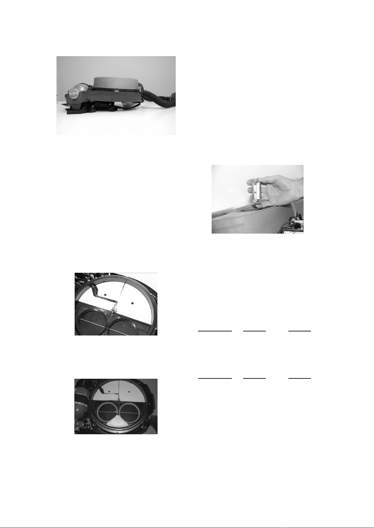
2. Verify that each carbon dioxide
scrubber canister has an o-ring
installed.
2. Verify that each carbon dioxide
scrubber canister has an o-ring
installed.
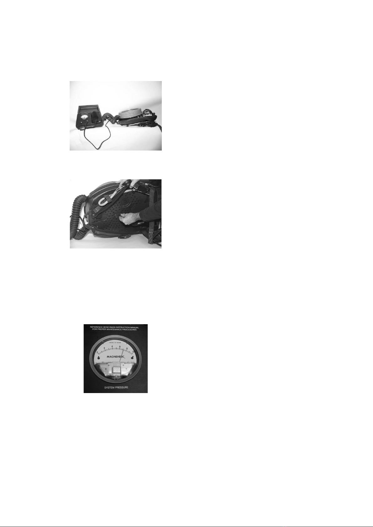
3. Install two carbon dioxide scrubber
canisters into the breathing chamber
making sure that they are properly
aligned and fully seated into position
as depicted below.
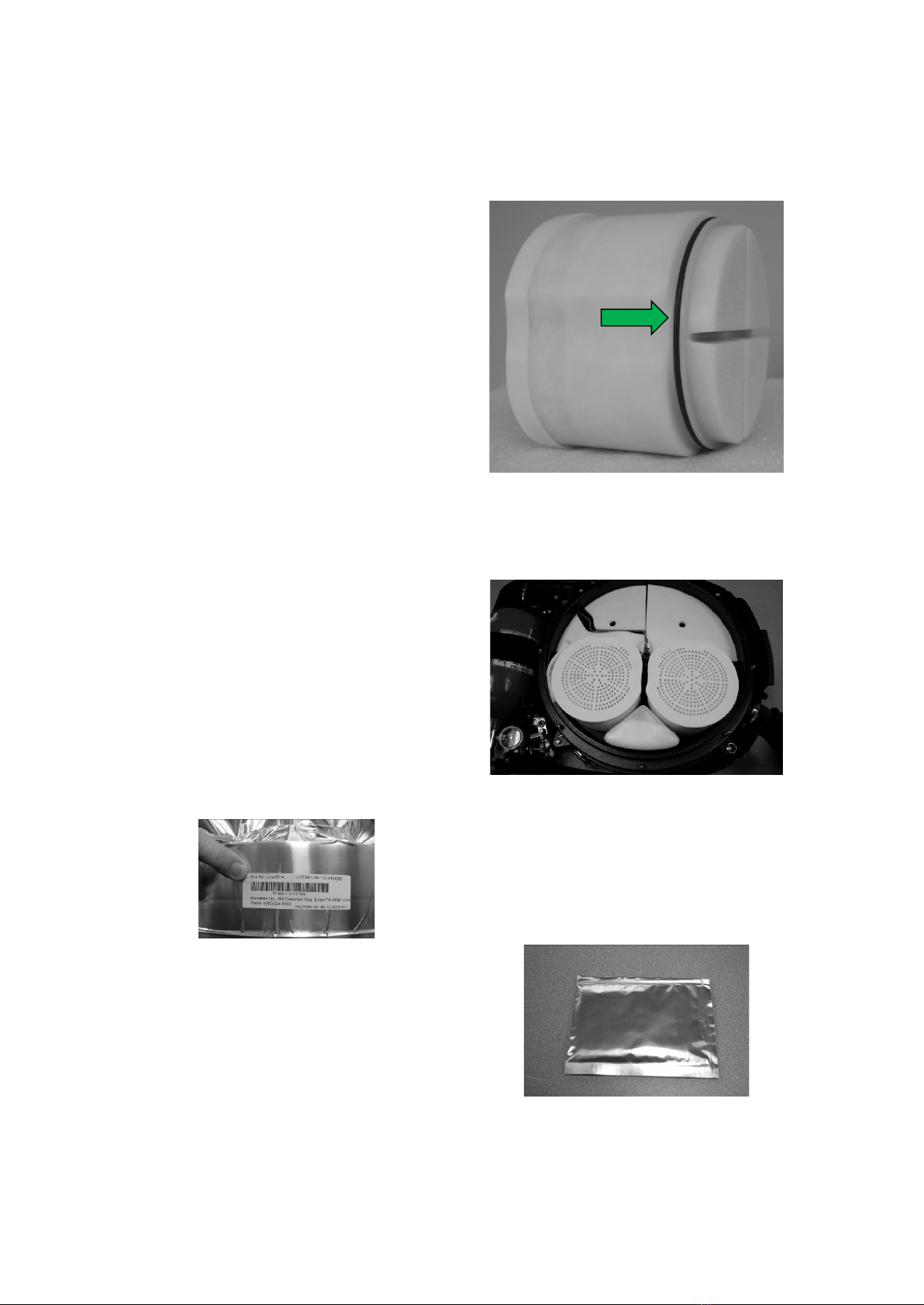
4. Remove the moisture pad, depicted
below in sealed bag, from the sealed
pouch and install it into the breathing
chamber as depicted.
4. Remove the moisture pad, depicted
below in sealed bag, from the sealed
pouch and install it into the breathing
chamber as depicted.

BioPak 240R Benchman Manual
A47D257, Revision M
June 2023
15
Proper moisture pad installation.
WARNING: Failure to install the
moisture pad can lead to scrubber
flooding that will result in elevated
carbon dioxide levels in the breathing
gas that may lead to injury or death.
5. Install and secure the breathing
chamber lid.
6. Date and initial the maintenance tag
under CO2 Scrubber Replaced.
The expiration date of pre-packed
carbon dioxide scrubbers will be the
shorter time period between the
following two factors:
1-year from date of scrubber
installation into BioPak; or,
“Use By” date provided on packaging
of carbon dioxide scrubber.

BioPak 240R Benchman Manual
A47D257, Revision M
June 2023
16
4. Long Term Maintenance
Procedure
In addition to normal turn around
maintenance, the apparatus shall be
visually inspected and pressure tested on
a periodic basis as outlined below:
Used 1 time/month: monthly
Used <1 time/month: quarterly
In Long Term Storage: every 6
months
A Maintenance Log Sheet is provided in
this manual to assist in tracking long-term
maintenance procedures.
4.1 Visual Inspection
Remove the upper housing and visually
inspect the apparatus for signs of wear,
abuse, loose connections or other
damage. Repair as necessary.
Verify that the apparatus is properly
sealed against the ambient environment
by the presence of the storage plug.
4.2 Demand Valve Functional Test
1. Vent the BioPak of all internal
pressure.
2. Open the oxygen cylinder and listen
for the sound of gas escaping into the
breathing chamber. The sound will
last approximately 1-3 seconds. This
signals that the demand has properly
opened.
3. After 1-3 seconds the sound of gas
escaping into the breathing chamber
must cease. This signals that the
demand valve has properly closed.
4.3 Constant Flow Test
1. Perform the test as described in
Section 3.8.
4.4 Vent Valve Functional Test
1. Replace the seal plug from the
facepiece adapter with the leak test
adapter from the test kit and connect
the barb of the adapter to the barb of
the service kit using rubbing tubing.
2. Fill the apparatus by depressing the
emergency bypass valve in several
short burst. Observe the pressure
reading on the service kit. The
apparatus pressure should remain at
or below 2” water column pressure
after releasing the emergency bypass
valve.
4.5 Low Pressure Leak Test
1. Perform the test as described in
Section 3.9.
4.6 High Pressure Leak Test
1. Place the apparatus on a flat surface.
Ensure that the test keys of the Low
Pressure Leak Test have been
removed. The oxygen cylinder must
be charged to at least 103 bar (1500
psi).
2. Open the oxygen cylinder valve and
wait until the apparatus pressure
gauge has reached its final reading.
3. Inspect each plumbing connection
with oxygen safe leak detection fluid
by wetting each joint, waiting 60-
seconds, then inspecting each joint for
the sign of bubble formation. The
presence of bubbles will indicate a
leak.
4. Repair any leaking joint or replace the
leaking components. Repairs must
be performed with the BioPak fully
vented of all internal pressure.
5. Close the oxygen cylinder valve and
depress the emergency vent valve to
depressurize the apparatus.
Note: A digital high-pressure test
apparatus is available from
Biomarine that will eliminate the
need for the use of leak detection
fluid during testing.

BioPak 240R Benchman Manual
A47D257, Revision M
June 2023
17
4.7 Emergency Bypass Valve
Functional Test
1. Open the oxygen cylinder and depress
the emergency bypass valve for 1-2
seconds. The sound of gas escaping
into the breathing chamber shall be
heard whenever the valve is
depressed and shall cease whenever
the valve is released.
2. Close the oxygen cylinder.
4.8 Alarm Test
1. Perform the test as described in
Section 3.10.
4.9 Maintenance Tag Validation
11. Inspect the maintenance tag that
should be attached to the apparatus in
a conspicuous and consistent location.
Verify that all portions of the tag are
properly completed.
2. Verify that the apparatus oxygen
cylinder is fully charged to 207 bar
(3000 psi) and top off if necessary.
3. Replace the upper housing.
BioPak 240R Benchman Manual
A47D257, Revision M
June 2023
18
5. General Service Procedures
5.1 Scheduled Component
Inspection
Breathing Diaphragm:
Annually, remove the center section and
disconnect the diaphragm from the center
section by loosening the clamp. Inspect
the diaphragm for signs of wear, cracking
or rot. Disassemble the vent valve and
inspect all components and lubricate as
needed.
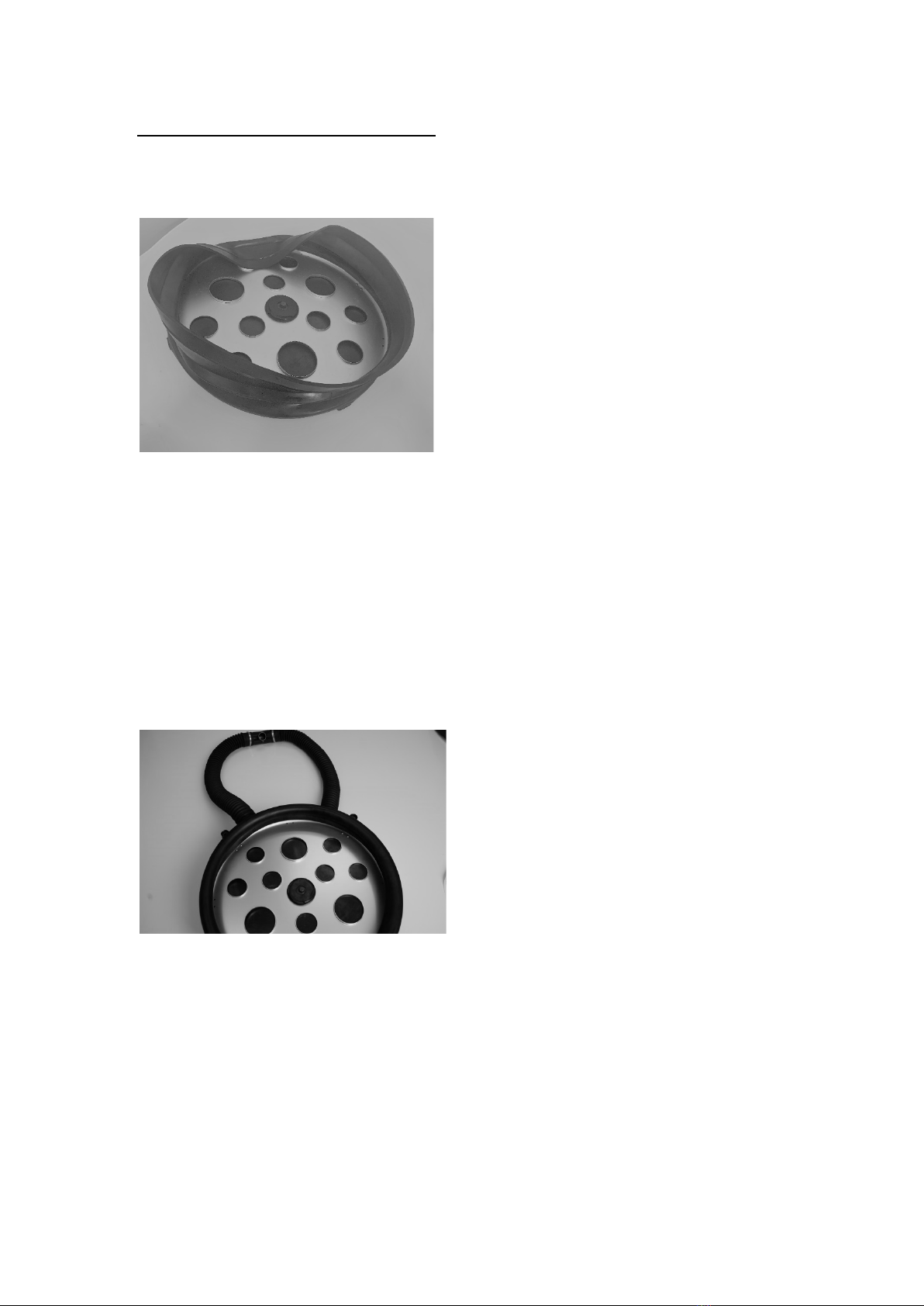
Diaphragm Alignment: Proper
diaphragm alignment is depicted below.
Note the positioning of the three large
holes in the diaphragm plate in relation to
the breathing chamber mounting feet and
the breathing hoses. Reference diagram
in Section 7.6.
Facemask: Inspect all rubber
components for signs of wear, tears, rips,
cracking or rot. Inspect the lens for signs
of cracking, breakage, crazing or other
damage.
Breathing Hoses: Inspect for signs of
wear, tears, rips, cracking or rot.
O-ring Seals: If the apparatus has
passed the high and low pressure leak
tests the o-ring integrity is acceptable.
Reference Appendix A for a schedule of o-
ring seal inspection and lubrication.
5.2 System Lubrication
Leaks discovered during high and low
pressure testing are often caused by
damaged or improperly lubricated o-rings.
Replace faulty o-rings and follow the
guides below for o-ring handling and
lubrication.
•Never pry o-rings from glands with
a screwdriver. Remove o-rings by
hand or using the pick tool
provided in the service kit.
•Unless otherwise directed, do not
lubricate o-rings while they are still
seated within their gland.
•Do not use heavy coats of
lubrication. Proper o-ring
lubrication will result in a shiny
surface without lumps.
•Do not stretch or deform o-rings
during handling.
•Visually inspect under bright
lighting and inspect by feel, o-
rings for signs of damage such as
nicks, cuts, tears, or abrasion.
•Christo-Lube™ and Dow 111™
are the only lubricants approved
for use in the apparatus.
Reference Appendix A for
lubrication type for each seal.
•NEVER lubricate the seal that sits
between the oxygen cylinder and
the pressure regulator.
5.3 Oxygen Cylinder
The cylinder should be inspected regularly
for signs of damage to the outer wrapping.
Cylinders that are cracked, flaking or show
exposed fibres should be immediately
retired from service.
Cylinders will require periodic hydro-static
testing per national requirements. Typical
intervals are every 5-years from the date
of manufacture. Cylinder testing should be
conducted by an authorized testing facility.
Cylinders that have been hydro-static
tested shall be cleaned for high-pressure
oxygen service as per national standards.
Cylinders are to be retired from service 15-
years after the date of manufacture.

BioPak 240R Benchman Manual
A47D257, Revision M
June 2023
19
5.4. Alarm Battery Replacement
Procedure
The alarm system battery shall be
replaced after 200-hours of use, after 6-
months or after the alarm system low
battery alarm (RED, GREEN, BLUE
flashes with corresponding horn
sounding), whichever occurs first.
Battery replacement can only be
performed in an area known to contain
non-hazardous (non-explosive)
atmospheres.
1. Remove the upper cover.
2. Disconnect the electrical line to the
center section.
3. Remove the alarm housing from the
apparatus. Inspect the housing for
cracks or damage. Dust-tight and
water-tight integrity are required for
use in potentially explosive
atmospheres. The alarm module will
require replacement if any damage
to the housing is discovered.
4. Remove the battery cover. Inspect
the cover and gasket for cracks or
damage. The battery cover door
will need to be replaced if any
damage is found.
5. Remove the battery from the alarm
housing and replace with a fresh
battery. Inspect the interior of the
battery compartment for the presence
of corrosion, liquid or dust. Clean if
necessary or replace the alarm
module.
6. Install the replacement battery into the
battery compartment making sure to
proper align the battery poles.
Use only battery types as specified for
replacement.
7. Replace the battery cover making sure
that the gasket is properly positioned
and that the gasket is not damaged in
any way. The battery door should
only fit in one orientation on the
module.
8. Install the alarm housing into the
apparatus.
10. Connect the electrical line from the
center section to the alarm housing.
11. Conduct the Alarm Test as described
in section 3.10.
12. Install the upper housing.
5.5 Flow Restrictor Replacement
Procedure
1. Remove the upper housing and vent
the BioPak of all internal pressure.
2. Use the ¼” hex driver from the service
kit to the remove the flow restrictor.
Be sure to remove and discard the
head gasket and o-ring of the
existing flow restrictor.
3. Use the ¼” hex driver from the service
kit to the install a replacement flow
restrictor.
4. Perform the high-pressure leak test as
directed in long term maintenance.
5. Perform the constant add test as
directed in turn around maintenance.
6. Replace the upper housing.

BioPak 240R Benchman Manual
A47D257, Revision M
June 2023
20
5.6 Factory Service and Training
Factory service and personnel User and/or
Benchman Training can be provided by
contacting the location listed below.
Biomarine, Inc.
ATTN: Service Department
1001 Corporate Lane, Suite 240
Export, PA 15632
USA
Tel: (412) 856-9200
Fax: (412) 856-9203
Web: www.Biomarineinc.com
•Customers can also contact their
local authorized Biomarine
Distributor for training, product
support, emergency support or
maintenance.
•The BioPak 240R- User and
Benchman manuals can be
provided in electronic format upon
request.
•Reference documentation
supplied with sales order for
standard terms of warranty.
•Training posters, manuals, MSDS
data and other training materials
are available for download from
the Biomarine website.
•Contact Biomarine prior to
returning any equipment.
To better serve your needs, please
provide the following information when
contacting Biomarine.
•Apparatus Serial Number
(Located internal to the BioPak,
beneath the oxygen cylinder)
•Date of purchase
•Approximate number of uses
•Description of problem
•Actions taken to correct problem
•Contact name, address and phone
number with area or country code
and email address
•Please provide your current email
address with all service
correspondence.
6. STORAGE GUIDELINES
Follow the guidelines below for proper
storage of the apparatus.
•Storage plug shall be installed.
•Never store a wet apparatus. The
apparatus must be fully dry before
storage to prevent the growth of
mold, germs and bacteria.
•Never store an apparatus that has
not been fully cleaned and
disinfected.
•Store in a location free from
impact that could cause damage
to the apparatus.
•Store in the stated conditions of
ambient temperature and relative
humidity.
•Store in a location that will not
submerge the apparatus.
•Long Term Storage (storage of
BioPak for periods exceeding 6-
months without use): Follow all
of the above guidelines. The
BioPak should not be placed back
into service until all the
procedures associated with Turn
Around and Long Term
maintenance have been
performed and passed. No
additional outer packaging is
necessary for long term storage or
transport.
.
Other manuals for BIOMARINE BIOPAK 240-R
1
This manual suits for next models
1
Table of contents
Other CSE Respiratory Product manuals


