CSiSC PSiSC HD-58124 User manual

HD-58124
Toilet Partition Installation
Manual
PHONE: 803-252-3020
FAX: 803-256-7769

www.psisc.com
803-252-3020
2
ATTENTION
DO NOT MIX
FASTENER PACKS
EACH FASTENER PACK HAS THE NECESSARY
BOLTS, BARRELS AND SCREWS TO INSTALL
THE RESPECTIVE PANEL, PILASTER OR DOOR.
TORX HEAD BITS ARE PACKED IN THE EXTRA
FASTENER PACKS.

www.psisc.com
803-252-3020
3
TABLE OF CONTENTS
STEP PAGE
1 TOOLS REQUIRED................................... 4
2 GETTING STARTED ................................. 5
3 MARK THE PARTITION LAYOUT............. 6
4INSTALL THE PANELS............................. 8
5INSTALL THE WALL PILASTER
5A USING ‘Z’ BAR ANCHORING SYSTEM .......... 10
5B USING STANDARD LEVELING DEVICE......... 12
6INSTALL THE PILASTERS ..................... 14
7 INSTALL THE HEADRAIL ....................... 17
8 ATTACH THE DOORS ............................ 18
9 ATTACH THE DOOR HARDWARE ........ 20
10 ADJUSTABLE ALUMINUM PILASTERS. 22
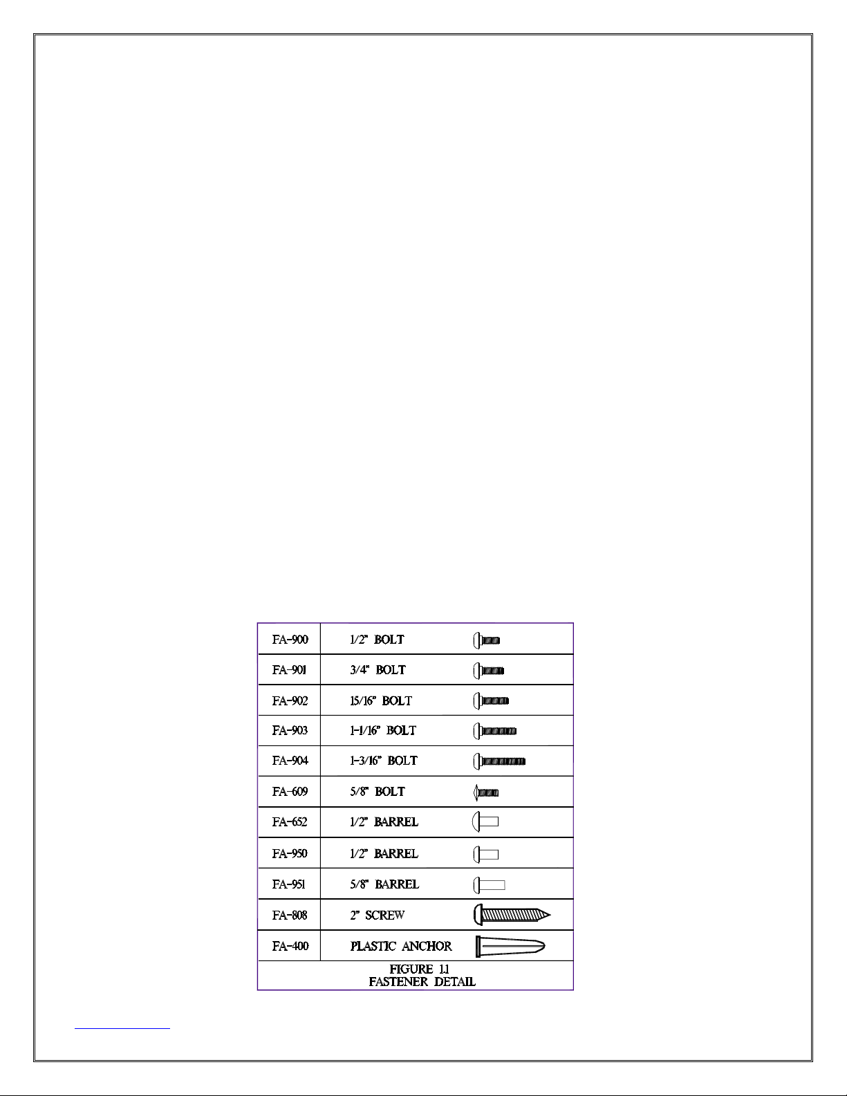
11 BOLT AND BARREL SIZES .................... 23
www.psisc.com
803-252-3020
4
1 TOOLS REQUIRED
xTAPE MEASURE
x4 FOOT LEVEL
xRATCHET TYPE BIT DRIVER (torx head bits supplied)
xFLAT HEAD SCREWDRIVER
xPHILLIPS HEAD SCREWDRIVER
x1 WAY SCREWDRIVER
xTWO 9/16" OPEN END WRENCHES
xHAMMER
xTWO 12" BLOCKS
xDRILL
xROTARY HAMMER DRILL
xHACKSAW
x5/16" CARBIDE TIPPED HAMMER DRILL BIT
x5/8" CARBIDE TIPPED HAMMER DRILL BIT
x1/4" HIGH SPEED STEEL DRILL BITS
xCHALK BOX

www.psisc.com
803-252-3020
5
2 GETTING STARTED
2.1 Find the packing list in the box marked “Packing List”
2.2 Check delivered materials and make sure no parts are
damaged or missing.
2.3 Check dimensions in each bathroom against the shop
drawings marked “For Field Use”. Make notes of
differences.
2.4 Clear bathrooms to provide workroom.
Thank you for choosing partitions from Partition Systems Inc. of South
Carolina. We appreciate your business. At Partition Systems, we strive to
provide the industry’s best partitions with comprehensive installation
guides.
If you need assistance, have questions or comments; contact our customer
service department at:
Customer Service
Partition Systems Inc. of South Carolina
PO Box 181, Columbia, SC 29202
(803) 252-3020, Fax: (803) 252-6030
Partition Systems International of South Carolina
825 Garland St.
Columbia, SC 29201

www.psisc.com
803-252-3020
6
3 MARK THE PARTITION LAYOUT
3.1 Establish and mark the center of the panels across the
back wall according to shop drawings. For end-panels and
alcove-panels mark the outer edge. (See fig.3.1)
3.2 Establish and mark the panel-brackets on the back wall
18” and 64” from the finished floor.
3.3 Establish and mark the wall-pilaster location on the side
wall according to shop drawings. (See fig.3.1)
3.4 Establish and mark the pilaster-brackets on the side wall
18” and 64” from the finished floor.
3.5 Establish and mark the outer edges of each pilaster from
the back and side walls according to shop drawings. (See
fig.3.1)
3.6 Mark and drill holes for the floor fasteners.
3.6.1 For leveling devices mark 5/8” in from the end of the
pilaster(s), centered from front to back. Drill a 2” deep hole
in the floor with a 5/8" bit.
3.6.2 For shoe/heel place the shoe on the floor centered between
the outer edges of the pilaster Using the shoe as a template,
mark the holes. Drill a 2” deep hole in the floor with a 5/16"
bit. (See fig.5-B.1)
3.7 Mark wall bracket mounting holes using the brackets as a
template. Center and level the brackets before marking
(See fig.3.1). For end-panels and alcove-panels use the
outer edge.
3.8 Drill 5/16" holes for wall brackets.
3.9 Insert plastic anchors (FA-400) into holes.
3.10 Secure wall and pilaster brackets with 2” stainless steel
screws (FA-808).(See fig.3.2)

www.psisc.com
803-252-3020
7

www.psisc.com
803-252-3020
8
4 INSTALL THE PANELS
4.1 Place a 12" high support in position to hold up the panels.
(see fig. 4.1)
4.2 Set the panel on the support and slide the panel into the
wall brackets until the bottom is ½” from the wall.
4.3 Drill the bottom bracket hole through the panel with a ¼”
drill bit and secure with a ½" bolt (FA-900) and a ½" barrel
(FA-950).
4.4 Level the top of panel.
4.5 Drill the top bracket hole with a ¼” drill bit and secure with
a ½" bolt (FA-900) and a ½" barrel (FA-950).
4.6 Repeat steps 4.1 through 4.5 for each panel.

www.psisc.com
803-252-3020
9

www.psisc.com
803-252-3020
10
5 INSTALL THE WALL PILASTER
5A USING ‘Z’ BAR ANCHORING SYSTEM
5A.1 Place a lead anchor into the floor holes from step 3.6.
5A.2 Screw a 3/8" x 3½” threaded rod into the lead anchor. Place a
3/8" flat washer and 3/8" nut onto the rod and tighten with a 9/16"
wrench to secure the lead anchor.
5A.3 Place a second 3/8" nut and 3/8” flat washer onto the threaded
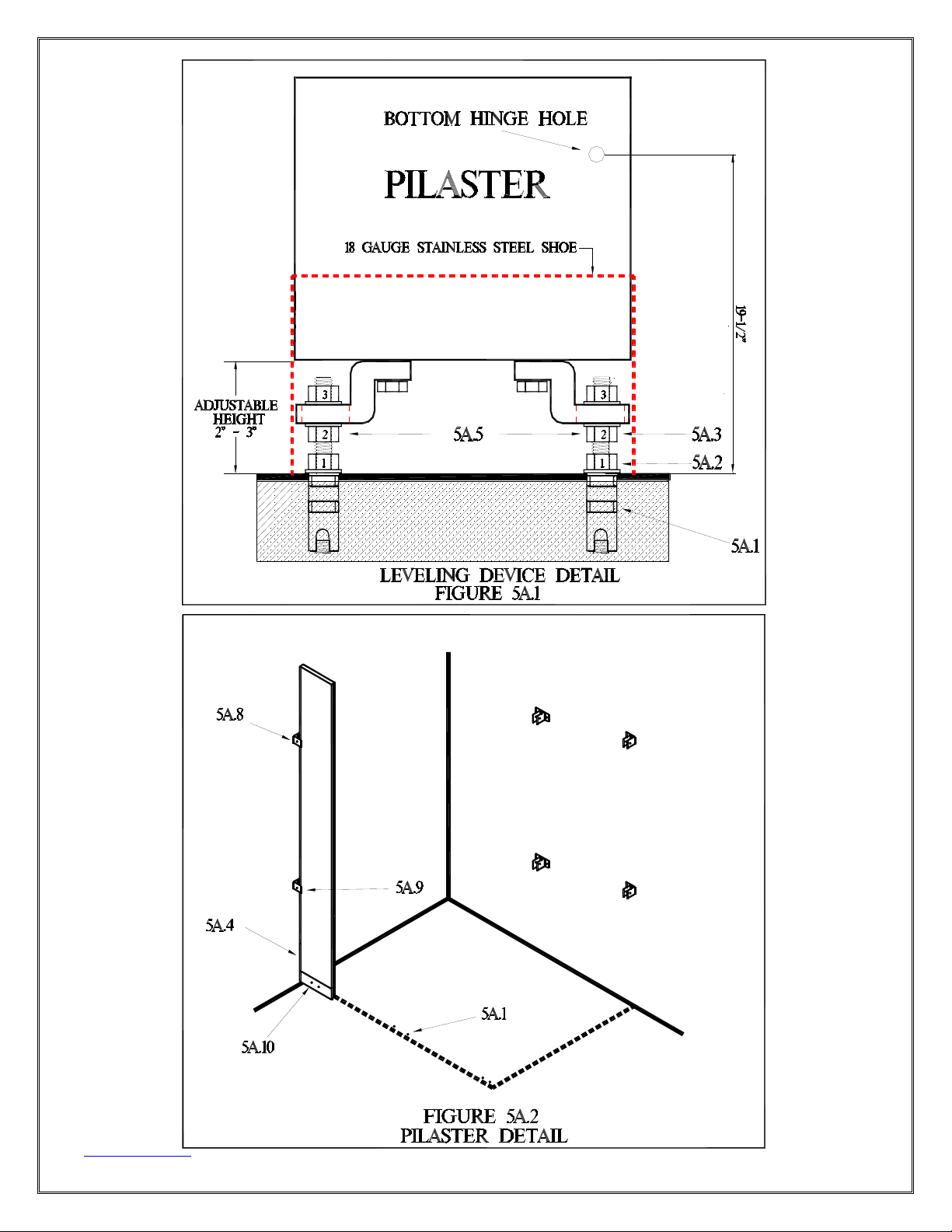
rod. Move the nut half way down the rod. (See figure 5A.1)
5A.4 Place the wall-pilaster onto the threaded rod and slide it into the
wall mounted pilaster-brackets.
5A.5 Adjust the 3/8" nut to raise (lower) the pilaster until the bottom
hinge hole is 19½” off the finished floor. (See figure 5A.1)
5A.6 Place the pilaster shoe onto the pilaster and place the pilaster
onto the threaded rod. Place a third washer and nut onto the
threaded rod.
5A.7 Set the bottom gap between the wall and the pilaster according
to the shop drawings. Tighten the top nut to secure the pilaster.
5A.8 Level the pilaster. Drill the top pilaster bracket hole with a ¼”
drill bit. Secure with a ½” bolt (FA-900) and a 5/8" barrel (FA-951).
5A.9 Drill the bottom bracket hole. Secure with bolt and barrel.
5A.10 Drill through the shoe and pilaster. Secure with a ½” bolt (FA-
900) and a 5/8" barrel (FA-951).
www.psisc.com
803-252-3020
11

www.psisc.com
803-252-3020
12
5 INSTALL THE WALL PILASTER
5B USING STANDARD LEVELING DEVICE
5B.1 Mount the shoe/heel to the floor with 2” stainless steel
screws (FA-808).
5B.2 Place the pilaster into the shoe/heel and slide the wall-
pilaster into the wall brackets.
5B.3 Using the Leveling Bolt in the bottom of the pilaster raise
(lower) the pilaster to where the bottom hinge hole is 19½”
off the finished floor. (See figure 5B.2)
5B.4 Place the pilaster into the shoe/heel. Slide the pilaster into
the wall brackets. (See figure 5B.1)
5B.5 Set the bottom gap between the wall and the pilaster
according to shop drawings.
5B.6 Drill the bottom bracket hole through the pilaster with a ¼”
drill bit. Secure with a ½” bolt (FA-900) and a 5/8" barrel.
(FA-951)
5B.7 Check level and drill the top hole through the pilaster with a
¼” drill bit. Secure with a ½” bolt (FA-900) and a 5/8" barrel.
(FA-951)
5B.8 Drill ¼” hole(s) through the shoe, heel and pilaster. Secure
the shoe with ½" bolts (FA-900) and 5/8" barrels. (FA-951)

www.psisc.com
803-252-3020
13

www.psisc.com
803-252-3020
14
6 INSTALL THE PILASTERS
6.1 Prepare the pilaster floor fasteners. For leveling device follow
steps 5A.1 through 5A.3. For shoe & heel follow step 5B.1.
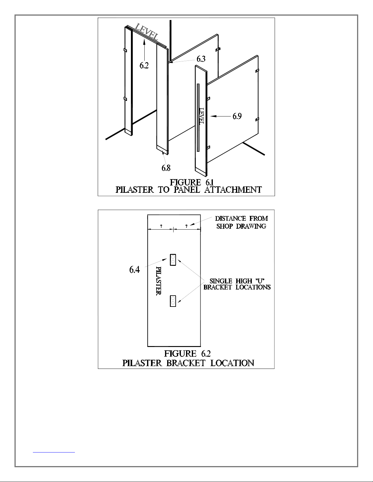
6.2 Place the pilaster onto the leveling device (or heel) and level the
top of the pilaster with the pilaster at the wall.
6.3 On the back of the pilaster mark the center of the panel
according to shop drawings. (See fig 6.2)
6.4 Mark the pilaster where the brackets will be located at 18” and
64” off the floor for shoe/heel, 17” and 63” for leveling device.
6.5 Place the pilaster-to-panel brackets onto the pilaster where the
marks are made. Mark the mounting holes. (see fig 6.2)
6.6 Drill ¼” holes through the pilaster and secure the pilaster-to-
panel brackets with ½" bolts (FA-900) and 5/8" barrels (FA-951).
6.7 Place the shoe onto the pilaster and place the pilaster onto the
leveling device (or shoe/heel). Slide the panel into the bracket.
6.8 Secure the pilaster.
6.8.1 For ‘Z” bar anchoring system, place a 3/8" washer and nut onto the
threaded rods and tighten to secure the pilaster.
6.8.2 For standard leveling device drill level top of pilaster with pilaster at
wall, drill a ¼” hole through the shoe and the pilaster. Secure with ½"
bolts (FA-900) and 5/8" barrels (FA-951).
6.9 Level the pilaster front and drill through the top panel bracket
hole. Secure the panel with a ½" bolt (FA-900) and ½" barrel. (FA-
950). Drill and secure the remaining panel bracket hole(s).
6.10 Repeat steps 6.2 through 6.9 for each pilaster.
6.11 For leveling devices secure the shoes. Drill a ¼” hole through
the pilaster. Secure the shoes with ½" bolts (FA-900) and 5/8"
barrels. (FA-951)
www.psisc.com
803-252-3020
15
SEE SHOP DRAWINGS FOR DISTANCE BETWEEN
PILASTERS BEFORE FASTENING PILASTERS TO FLOOR.

www.psisc.com
803-252-3020
16
7 INSTALL THE HEADRAIL
7.1 Measure and cut the front headrail to the appropriate length. For
large openings, cut the headrail as long as possible with the cut in
the center of a pilaster.
7.2 Lay the headrail on top of the pilasters and using the headrail
bracket as a template attach to wall using the supplied fasteners.
7.3 Drill a ¼” hole through the headrail bracket, headrail and the wall-
pilaster. Secure with a 15/16" bolt (FA-902) and 5/8" barrel (FA-
951).
7.4 For each pilaster, measure and mark the door opening width
according to shop drawings. Drill a ¼” hole through the headrail
and the pilaster. Secure with a ¾” bolt (FA-901) and a 5/8" barrel
(FA-951). See the notes to determine how many holes to drill.
7.5 For in-corner and free-standing configurations place an end-cap
and a corner headrail bracket onto the end of the headrail. Drill a
¼” hole through the headrail bracket, headrail and pilaster.
Secure with a 15/16" bolt (FA-902) and 5/8" barrel (FA-951).
7.6 Measure from the top of the panel to the bottom of the corner
headrail bracket.
7.7 Measure, mark and secure a headrail bracket on the wall at the
height measured in step 7.6.
7.8 Measure from the back wall to the corner headrail bracket. Cut a
piece of headrail to fit between the two brackets. Drill a ¼” hole
through the headrail and bracket and secure with 15/16" bolts (FA-
902) and 5/8" barrels (FA-951).
Pilaster Size # Bolts Location
< 7” 1 Centered
8” – 13” 2 2” from each end
> 14” 3 2” from each end and one centered

www.psisc.com
803-252-3020
17

www.psisc.com
803-252-3020
18
8 ATTACH THE DOORS
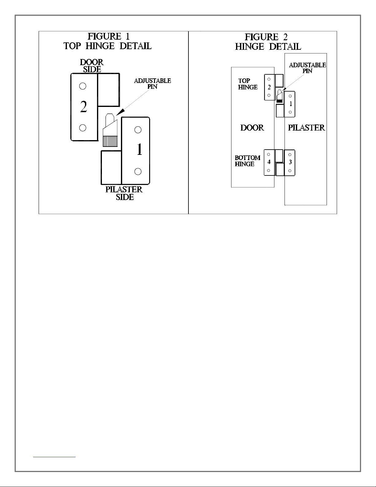
8.1 Secure part 1 of the top hinge onto the top of the pilaster
with ½" bolts (FA-900) and 5/8" barrels (FA-951). Keep the
adjustable pin in hinge part 1. (See fig. 1)
8.2 Secure part 2 of the top hinge onto the top of the door with
½" bolts (FA-900) and 5/8" barrels (FA-951). (See fig. 1)
8.3 Secure part 3 of the bottom hinge onto the bottom of the
pilaster with ½" bolts (FA-900) and 5/8" barrels (FA-951). (See
fig. 2)
8.4 Hang the door onto the pilaster.
8.5 Secure part 4 of the bottom hinge to the bottom of the
door using ½" bolts (FA-900) and 5/8" barrels.
www.psisc.com
803-252-3020
19
Notes:
xTo increase or decrease the default door opening reposition the
adjustable pin in the top hinge. The default position is 15oopen.
xFor the best installation place the barrel through the hinge.
xOn inswing doors the hinge is located on the inside of the stall.
On outswing doors the hinge is located on the outside of the stall.
xA right hand inswing hinge (SS-151) is also a left hand outswing
hinge. A left hand inswing hinge (SS-150) is also a right outswing
hinge.

www.psisc.com
803-252-3020
20
9 ATTACH THE DOOR HARDWARE
9.1 Mark the keeper position on the Pilasters.
9.1.1 For surface mounted latches, measure and mark the center of the
keeper 41" above the finished floor.
9.2 Using the keeper as a template, mark and drill ¼” holes through
the pilaster. Secure the keepers using ½” bolts (FA-900) and 5/8"
barrels (FA-951).
9.3 Mount the door latch. Position the surface mounted latches on
the inside of the door so the latch clears the keeper when the
door opens. Using the latch as a template, mark and drill ¼”
holes through the door.
9.3.1 For inswing and outswing doors, secure the latch with ½" bolts (FA-
900) and 5/8" barrels (FA-951).
9.3.2 For outswing doors secure the door pull with ½" bolts (FA-900) and
5/8" barrels (FA-951). Secure the door pull on the outside of the door.
9.4 Mount the coat hook / bumper
9.4.1 For inswing doors place the coat hook / bumper 4” from the top and
outer edge. Mark and drill ¼” holes in the door. Secure the coat
hook / bumper to the inside of the door with 5/8" bolts (FA-609) and ½”
barrels (FA-652).
9.4.2 For outswing doors center the coat hook 4” from the top. Mark and
drill ¼” holes in the door. Secure the coat hook with 5/8" bolts (FA-609)
and ½” barrels (FA-652).
9.4.3 For ADA doors see local specifications for coat hook placement.
(usually 48” from the finished floor)
Table of contents
Popular Bathroom Fixture manuals by other brands

Spectrum
Spectrum Pfister Saxton LG89-XGL1 Maintenance & Care Guide

agape
agape Novecento XL ACER1070 Assembly instructions

Spectrum Brands
Spectrum Brands Pfister Zeelan 8P8-WS2-ZLS Maintenance & Care Guide

Franke
Franke SATURN TB60 Installation and operating instructions

Duka
Duka VTW4 L Assembling instructions

ERGONOMIC
ERGONOMIC OBV3 instruction manual

Orbital Systems
Orbital Systems Oas Standard installation instructions

Aquadart
Aquadart venturi 6 AQ9359S installation instructions

Mira
Mira Platinum installation guide

BEMIS
BEMIS Plastic Pro UK004 Installation instruction

Lakes
Lakes SS100 manual

Hans Grohe
Hans Grohe AXOR Urquiola 11901000 Instructions for use/assembly instructions


