Mooney Series 20 Pilots Instruction Manual | 7© 2015 General Electric Company. All rights reserved.
Series 20 Pilot – Unloading and Loading Type Valve Installation
Personal injury, equipment damage, leakage or
explosion of accumulated gas or bursting of pressure
containing parts may result if this valve/ regulator is
overpressured or is installed where service conditions
could exceed the limits given in the specification of this
manual or on the nameplate, or where conditions
exceed any ratings of the adjacent piping or piping
connections. Verify the limitations of valve, pilot and
pipeline to ensure no device is overpressured. To avoid
such injury or damage, provide pressure relieving or
pressure limiting devices (as required by the U.S. code
of Federal Regulations, by the National Fire Codes of the
National Fire Protection Association, or by other
applicable codes) to prevent service conditions from
exceeding those limits. Additionally, physical damage
to the regulator, pilot, or tubing can cause personal
injury and/or property damage due to explosion of
accumulated gas. To avoid injury and damage, install
the valve in a safe location.
1. PERSONNEL: Installation of the Series 20 Pilot on the
Flowgrid Valve or any other manufacture’s valve should
be made by qualified personnel familiar with
high-pressure piping and Pilot-operated Regulators.
2. PRIOR INSPECTION: Inspect the Pilot for any damage
that might have occurred in shipping.
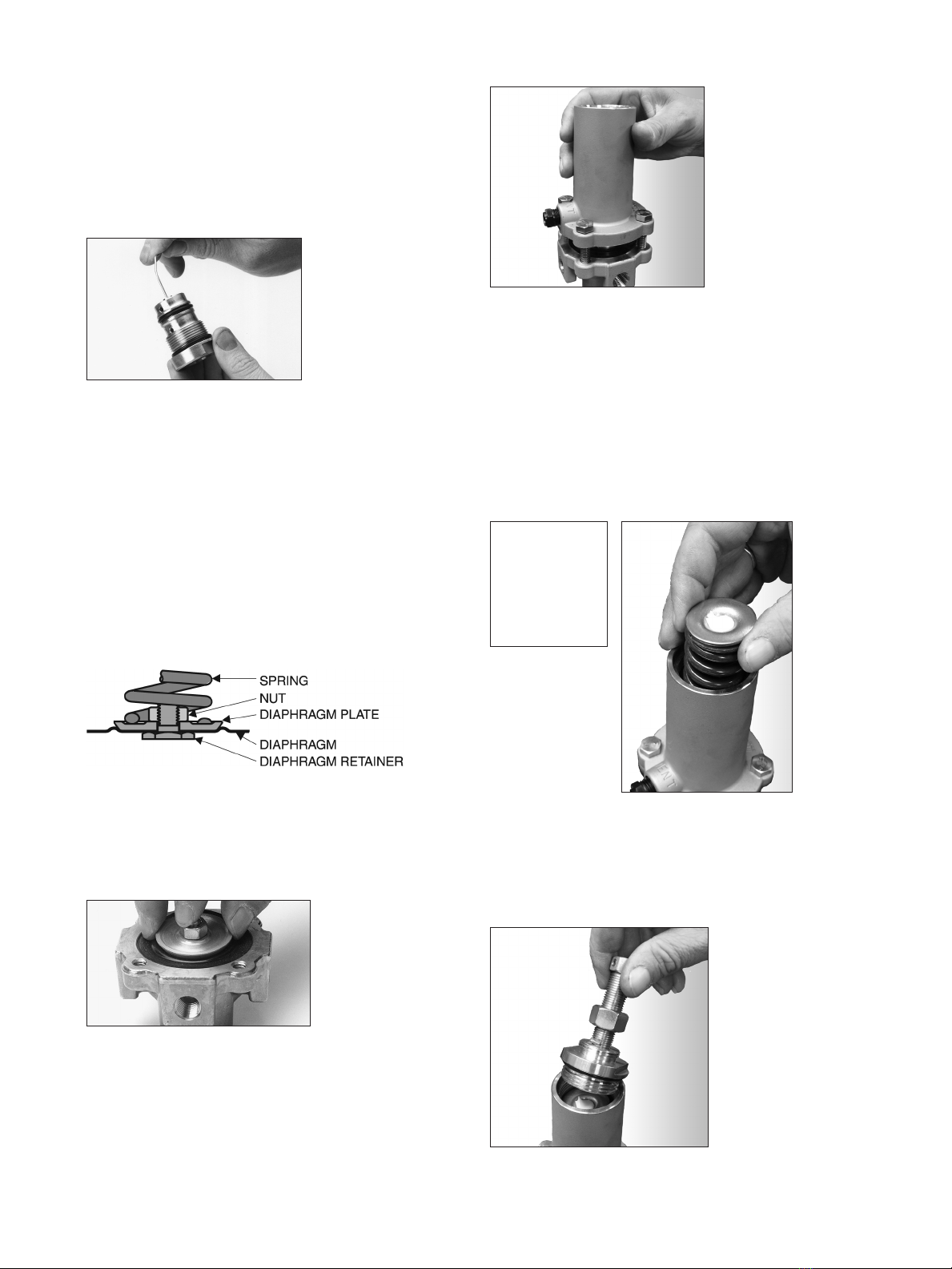
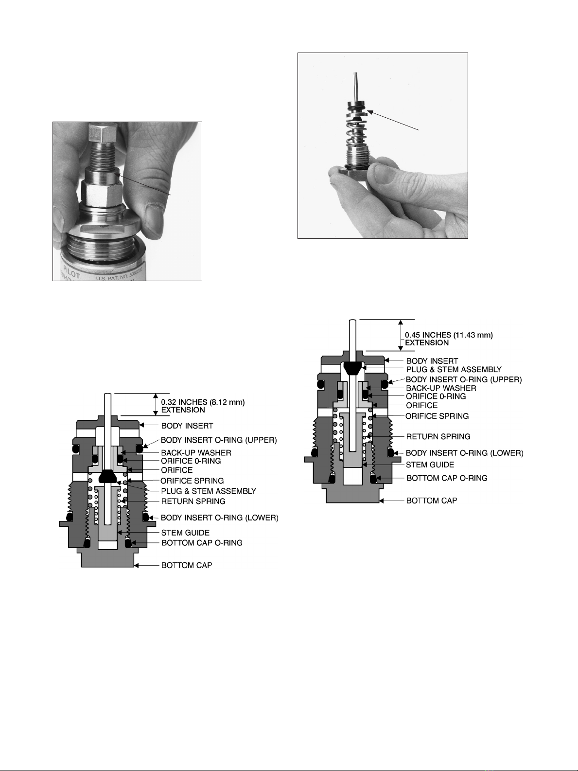
3. CONTROL ACTION: Inspect to make sure the Body
Insert Assembly (Cartridge) is in the correct operational
mode. Remove the Body Insert Assembly and measure
the stem extension from the Body Insert. (Refer to the
Maintenance section of this manual - Figure 18 &
Figure 20, page 10.)
Pressure Reducing Mode (PRV): the stem extends
0.32 inches (8.12 mm).
Back Pressure Mode (BPV): the stem extends
0.45 inches (11.43 mm).
If incorrect, follow the Body Insert Assembly
disassembly and assembly instructions in the
Maintenance section of this manual.
4. ORIENTATION: The Series 20 Pilot may be installed in
any position - the best position being one that provides
easiest access for pilot adjustment and valve
maintenance.
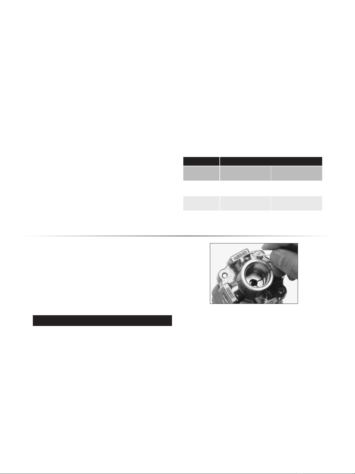
5. PILOT MOUNTING: Apply pipe dope (thread lubricant/
sealing compound) to a short (1-1/2 inch long) 1/4 inch
NPT Schedule 80 seamless pipe nipple. For a Mooney
Flowgrid the pilot is mounted by connecting the pilot
LOADING port to the Mooney Flowgrid spring case load-
ing port. For a Mooney FlowMax the pilot is mounted by
connecting the pilot OUTLET port to the Mooney Flow-
Max actuator loading port. When mounting the Mooney
Flowgrid valve it is best if the pilot OUTLET connection
is on the same side as the 1/4-inch NPT connections on
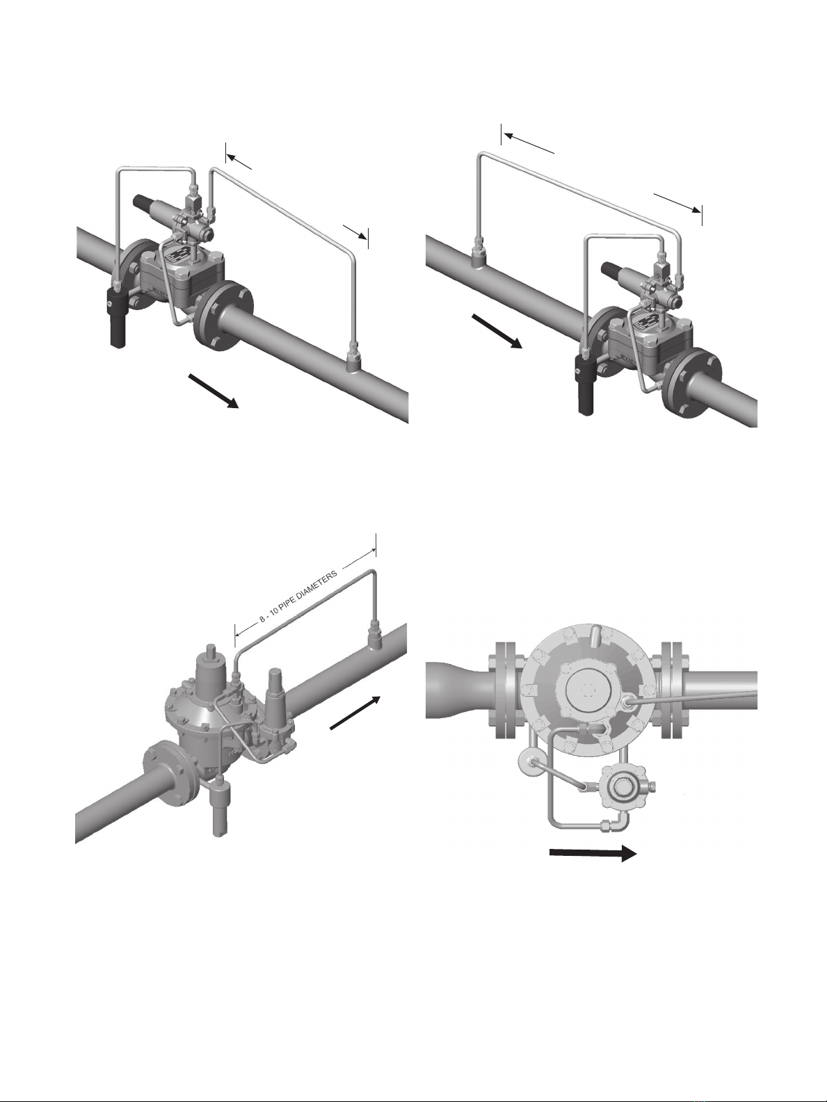
the valve body. (Refer to the Piping Schematics Page 6).
NOTE: To avoid galling when stainless steel to stainless
steel connections are made, use a lubricant (such as
NEVER SEEZ®by Bostik). For best results Lightly lubricate
the female threads. Mixing the lubricant with pipe dope
is also acceptable. When tightening do not exceed more
than 1/4 turn past the point the threads start to bind.
6. RESTRICTOR: Mount a rotary scratch type restricting
valve (such as the Type 24 Restrictor) to the Inlet port on
the Mooney Pilot. (Refer to Piping Schematics Page 6)
7. PILOT SUPPLY LINES: Run a 3/8-inch tubing or
1/4-inch pipe supply line from the upstream piping or
from the valve body connection on the inlet side of the
valve to the pilot restrictor. The pilot supply connection
should have a full and clean opening.
8. AFILTER in the pilot supply line is recommended to
remove dirt and other particulates that could affect
the restrictor or variable orifice in the pilot. Refer to
the Type 30 Filter I/O/M manual for installation
instructions.
WARNING
Gas regulators installed in confined or enclosed
spaces should be provided with adequate ventilation to
prevent the possibility of gas buildup or accumulation
from leaks and venting. Leaks or vented gas may
accumulate causing personal injury, death, or property
damage. Pilot spring cases and the regulator enclosure
should be vented to a safe area away from air intakes,
or any hazardous location. The vent lines and stacks
must be protected against condensation and plugging.
NOTE: For Series 20 pilots, lubricate the adjusting screw
with a light, nitrile rubber compatible grease such as
Lubriplate #105, or equivalent, at first opportunity,
and thereafter, annually and during any interim
maintenance.
For Series 20 or 20H pilots (brass), inspect the closing
cap for thread wear by verifying the torque required to
modify the set point is less than 6 ft-lbs (8.14 Nm) and
inspect for metal particles on the adjusting screw or
on the closing cap threads. This should be completed
at the first opportunity, and thereafter, annually and
during any interim maintenance.
The Series 20 pilot with Purple, Black, or White with a
Green Stripe have higher tendency to wear due to higher
spring pressure. Spring range (color) is indicated on the
spring range label located on the pilot.
If it is determined that closing cap thread wear has
occurred, it is recommended that the cap and adjusting
screw be replaced with a Closing Cap Assembly. For
Closing Cap Assembly retro-fit kits, contact your local
sales representative for ordering information.
WARNING