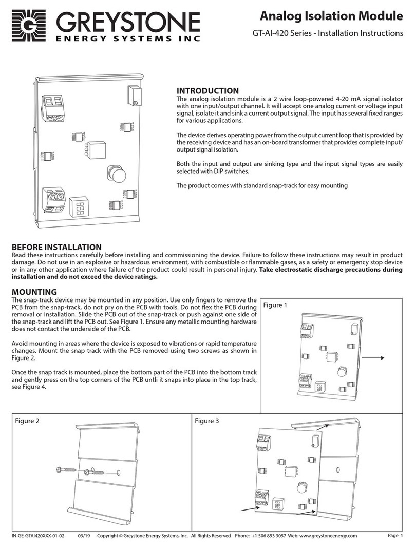
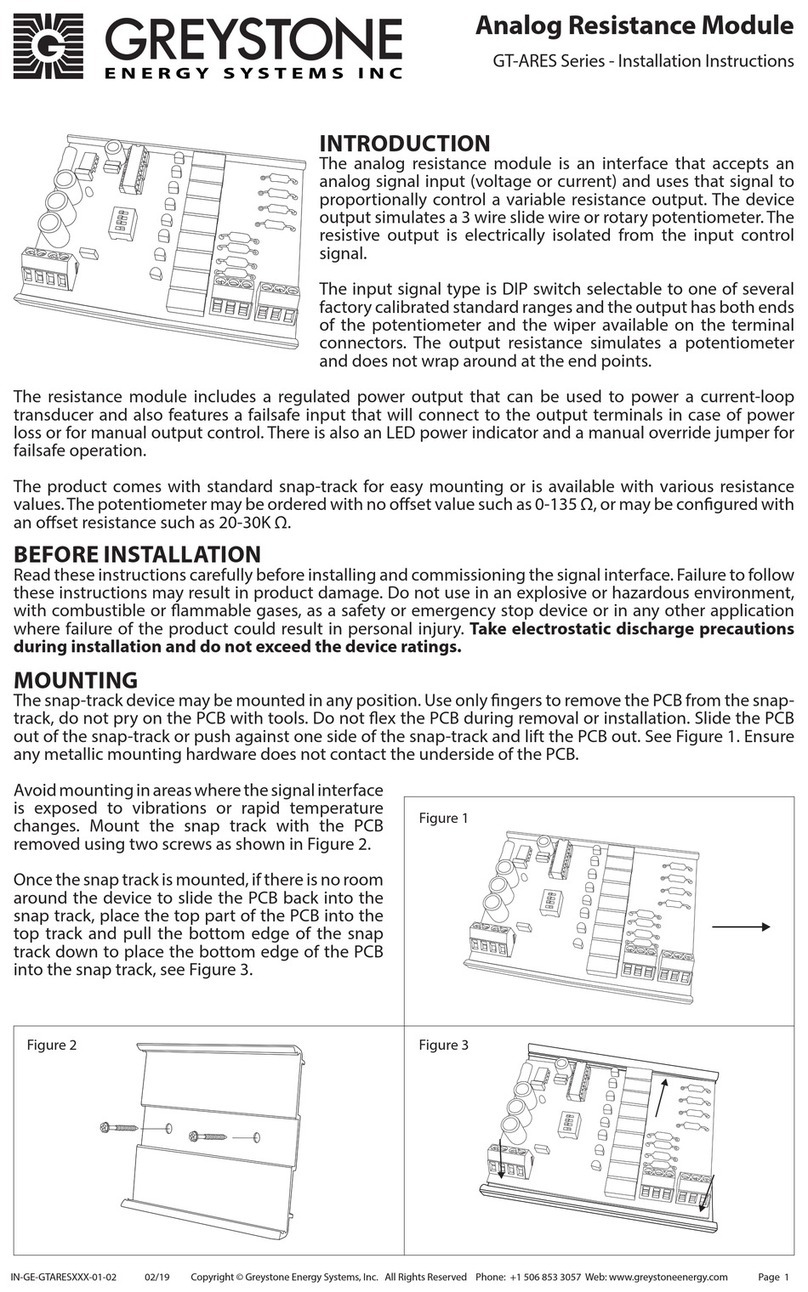
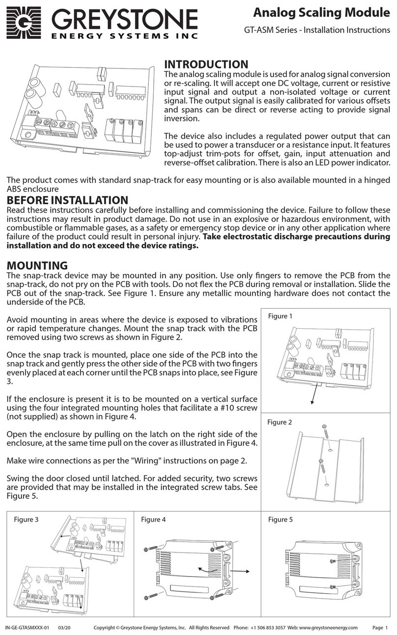
Greystone Energy Systems GT-AI Series User manual

Page 1
INTRODUCTION
The analog isolation module is a 3-way isolating
analog signal re-scaling module with one input-
output channel. It will accept one analog voltage
or current input signal, isolates it and re-scales
it to another voltage or current output signal.
The I/O signals have several pre-calibrated xed
ranges or may be custom calibrated for various
osets and spans and can be direct or reverse
acting to provide signal inversion.
The device has an on-board transformer that
provides power supply isolation and also input-
output signal isolation.
The module also includes a regulated +24 Vdc
power output that can be used to power a
transducer or a resistance input. It features top-
adjust trim-pots for oset and gain control, source or sink capabilities and an LED power indicator. Various
I/O signal types are easily selected with DIP switches.
The product comes with standard snap-track for easy mounting.
BEFORE INSTALLATION
Read these instructions carefully before installing and commissioning the device. Failure to follow these
instructions may result in product damage. Do not use in an explosive or hazardous environment, with
combustible or ammable gases, as a safety emergency stop device or in any other application where
failure of the product could result in personal injury. Take electrostatic discharge precautions during
installation and do not exceed the device ratings.
MOUNTING
The snap-track device may be mounted in any position. Use only ngers to remove the PCB from the snap-
track, do not pry on the PCB with tools. Do not ex the PCB during removal or installation. Slide the PCB
out of the snap-track or push against one side of the snap-track and lift the PCB out. See Figure 1. Ensure
any metallic mounting hardware does not contact the underside of the PCB.
Avoid mounting in areas where the device is
exposed to vibrations or rapid temperature
changes. Mount the snap track with the PCB
removed using two screws as shown in Figure 2.
Once the snap track is mounted, place the bottom
edge of the PCB into the bottom slot on the snap
track and then gently press the top edge in both
corners until the PCB snaps into the top slot of the
snap track. See Figure 3.
Figure 1
Figure 3Figure 2
IN-GE-GTAIXXX-01-02 03/19 Copyright © Greystone Energy Systems, Inc. All Rights Reserved Phone: +1 506 853 3057 Web: www.greystoneenergy.com
Analog Isolation Module
GT-AI Series - Installation Instructions

Page 2
FACTORY CONFIGURATIONS
The device preset is as follows:
• All DIP switches are set to o and must be congured for the correct signals type before use.
• Reverse/Normal jumper is set for normal acting operation (output follows input).
• Input type jumper is set for VOLTAGE signal.
• Output type jumper is set to VOLT and SOURCE.
DEVICE SETUP
Follow the procedure from beginning to end to congure the device for the required signal types.
INPUT CONFIGURATION
Set the input jumpers:
For voltage input signal type set the input jumper to the VOLT (0-20 volt) position
For current input signal type set the input jumper to either the I_LOW (0-1 mA low current) or I_HIGH (0-20
mA high input current) position.
Set the DIP switches:
If the required preset input signal type is listed in the table below, then set the 8 switches according to the
chart and the input will be correctly calibrated for that signal type. For example, if the input signal is 0-1 V,
then set the switch 2 ON and the others OFF and the input will be correctly calibrated for the 0-1 V range.
The 0-1 V range set-up is shown in the example picture.
Select An Adjustable Input Range
If the required input signal is not listen in the chart above, then one of the adjustable ranges must be used.
There are three adjustable ranges for voltage and one for current. Note that the minimum voltage span
(maximum - minimum) is 1 volt and the minimum current span is 4 mA.
For voltage input, determine the maximum input signal and select the adjustable range accordingly. For
example, if the input signal range will be 3-9 V then the maximum input will be 9 volts and the Adj. 10
V max range will be selected. Set the switches according to the chart below. For current input, set the
switches according to the Adj. 4-20 mA range.
Figure 4
Figure 5
1
2
3
4
5
6
7
8
INPUT
Output Signal Type 1 2 3 4 5 6 7 8
0-1 V OFF ON OFF OFF OFF OFF OFF OFF
0-5 V OFF ON OFF OFF OFF ON OFF OFF
0-10 V OFF ON OFF OFF OFF ON ON OFF
0-15 V OFF ON OFF OFF OFF ON OFF ON
0-20 V OFF ON OFF OFF OFF ON ON ON
1-5 V OFF OFF ON OFF ON ON OFF OFF
2-10 V OFF OFF ON OFF ON ON ON OFF
3-15 V OFF OFF ON OFF ON ON OFF ON
4-20 V OFF OFF ON OFF ON ON ON ON
0-1 mA OFF ON OFF OFF OFF OFF OFF OFF
0-20 mA OFF ON OFF OFF OFF ON OFF OFF
4-20 mA OFF OFF ON OFF ON ON OFF OFF
Output DIP Switch Settings
0-20 mA
Range
Input Type Input Type Input Type
I_HIGH
I_LOW I_LOW I_LOW
I_HIGH I_HIGH
VOLT
VOLT
VOLT
0-1 mA
Range
0-20 V
Range
IN-GE-GTAIXXX-01-02 03/19 Copyright © Greystone Energy Systems, Inc. All Rights Reserved Phone: +1 506 853 3057 Web: www.greystoneenergy.com

Page 3
To Calibrate the Adjustable Ranges
1. Congure the output signal type for 0-5 V
by setting the output jumpers to VOLT and
SOURCE. Then set the output DIP switches
according to the Output DIP Switch Settings
chart for the 0-5 V preset range.
2. Ensure the input jumper is set to VOLT or
I_HIGH as required and that the input DIP
switches are set according to the selected
adjustable range.
3. Rotate the MAX pot fully counter-clockwise (the factory setting).
4. Connect 24 Vac power to the device and turn the power on.
5. If the input signal range starts at 0 V or 0 mA (such as 0-7 volts), then skip to step 7. If the input signal
does not start at 0 V or 0 mA (such as 2-5 V), then continue to step 6 to calibrate the minimum signal.
6. Change the input DIP switch 4 setting from OFF to ON. Apply the minimum input signal. Measure the
dc voltage from TP1 (+) to TP2 (-) on the PCB. Adjust the MIN pot to obtain 0 Vdc on the meter. The
minimum value is now calibrated. Leave switch 4 in the ON position.
7. Connect a voltmeter to measure the output signal from OUT + to OUT -. Apply the maximum input
signal and adjust the MAX pot until the meter reads 5.00 volts. The maximum value is now calibrated.
OUTPUT CONFIGURATION
The input must be congured before selecting the output conguration.
Set the Output Jumpers
For voltage output signal type set the output jumpers to the VOLT (0-20 volt) and SOURCE positions.
For sourcing current output signal type set the output jumpers to the mA (0-20 mA) and SOURCE position.
For sinking output current signal type, set the output jumpers to the VOLT and SINK positions.
The NORM/REV jumper should remain set in the NORM position until all other settings are made. If, for
example, a 5-0 volt output is required then set up the device for a 0-5 volt output and then change the
jumper to the REV position.
Set the Output DIP Switches
If the required preset output signal type is listed in the table below, then set the 8 switches according to
the chart and the output will be correctly calibrated for that signal type. For example, if the output signal
is 4-20 mA, then set switches 4, 5, 6, and 8 ON and all others OFF and the input will be correctly calibrated
for the 4-20 mA output range.
If the required output signal is not listed in the chart above, then one of the preset oset/span ranges
could be used. Check the output signal requirements as follows; OFFSET = the minimum signal output,
SPAN = maximum signal output minus minimum signal output
Input Signal Type 1 2 3 4 5 6 7 8
Adj. 5 V max ON OFF OFF OFF* OFF ON OFF OFF
Adj. 10 V max ON OFF OFF OFF* OFF ON ON OFF
Adj. 20 V max ON OFF OFF OFF* OFF ON ON ON
Adj. 4-20 mA ON OFF OFF OFF* OFF ON OFF OFF
Input DIP Switch Settings
Figure 6
Figure 7
Figure 8
Output Signal Type 1 2 3 4 5 6 7 8
0-5 V ON OFF OFF OFF ON OFF ON ON
1-5 V OFF OFF OFF ON ON ON OFF ON
0-10 V ON OFF OFF OFF ON OFF OFF OFF
2-10 V OFF OFF ON OFF ON OFF OFF ON
0-20 mA ON OFF OFF OFF ON OFF ON ON
4-20 mA OFF OFF OFF ON ON ON OFF ON
Output DIP Switch Settings
Voltage
Output
Current
Source
Current
Sink
Output Type Output Type Output Type
SCR
Sink
SCR
Sink
SCR
Sink
mA
VOLT
mA
VOLT
mA
VOLT
1
2
3
4
5
6
7
8
OUTPUT
IN-GE-GTAIXXX-01-02 03/19 Copyright © Greystone Energy Systems, Inc. All Rights Reserved Phone: +1 506 853 3057 Web: www.greystoneenergy.com

Page 4
For example, if the output signal is to be 0-7 volts, then OFFSET = 0 V and SPAN = 7 V. Once these two
values are determined check the following charts for the available presets for oset and span.
Select a Preset Output Oset
If the OFFSET is 0, 1, or 2 volts or 0, 4, or 8 mA, then set the output DIP switches according to the following
chart. Switches 5 and 8 will be set later for the SPAN.
Select an Adjustable Output Oset
If the required OFFSET is not equal to one of the preset values in the above chart, then select the adjustable
oset as shown in the following chart. An example of this would be if the output signal is to be 3-15 volts,
then OFFSET = 3 V and SPAN = 12V.
To calibrate the adjustable oset:
1. Ensure the Input Conguration section is completed rst.
2. Set the output DIP switches 5-8 to the ON position
3. Connect 24 Vac power to the device and turn the power on.
4. For voltage output signal type, connect a voltmeter to measure the output voltage signal from OUT +
to OUT -. For current sourcing output signal type, connect a mA meter from OUT + to OUT - to measure
the output current signal. For current sinking output, temporarily set the output to sourcing (and mA)
and measure the output current as previously described, or measure the current at the OUT+ terminal
directly in sinking mode.
5. Apply the minimum input signal to the device input and then adjust the OFFSET pot for the correct
minimum output. The output oset value is now calibrated.
Select a Preset Output Span
If the SPAN is 1, 3, 4, 5, 6, 7, 8, or 10 volts or 4, 12, 16, or 20 mA, then set the output DIP switches according to
the following chart. Switches 1 to 4 have been set previously for the OFFSET. Remember, SPAN = maximum
minus minimum.
Select an Adjustable Output Span
If the required SPAN is not equal to one of the preset values in the above chart, then select the adjustable
span as shown in the following chart. An example of this would be if the output signal is to be 3-15 volts,
the OFFSET = 3 V and SPAN = 12 V. In this case, since SPAN = 12 V, select the Adj. 10-20 V option.
Figure 9
Figure 10
Figure 11
Output Signal Oset 1 2 3 4 5 6 7 8
0 V or 0 mA ON OFF OFF OFF * * * *
1 V of 4 mA OFF OFF OFF ON * * * *
2 V or 8 mA OFF OFF ON OFF * * * *
Output Signal Oset 1 2 3 4 5 6 7 8
Adj. 0-10 V OFF ON OFF OFF * * * *
Adj. 0-12 mA OFF ON OFF OFF * * * *
Output Signal Span 1 2 3 4 5 6 7 8
1 V or 4 mA * * * * ON ON ON ON
3 V or 12 mA * * * * ON ON ON OFF
4 V or 16 mA * * * * ON ON OFF ON
5 V or 20 mA * * * * ON OFF ON ON
6 V * * * * ON ON OFF OFF
7 V * * * * ON OFF ON OFF
8 V * * * * ON OFF OFF ON
10 V * * * * ON OFF OFF OFF
Output DIP Switch Settings
IN-GE-GTAIXXX-01-02 03/19 Copyright © Greystone Energy Systems, Inc. All Rights Reserved Phone: +1 506 853 3057 Web: www.greystoneenergy.com

Page 5
To Calibrate the Adjustable Span:
1. Ensure the Input Conguration section is completed rst.
2. Ensure the output DIP switches 1-4 have been set previously for the oset.
3. Connect 24 Vac power to the device and turn the power on.
4. For voltage output signal type, connect a voltmeter to measure the output voltage signal from OUT
+ to OUT -. For current sourcing output signal type, connect a mA meter from OUT + to OUT - to
measure the output current signal. For current sinking output, temporarily set the output to sourcing
(and mA) and measure the output current as previously described, or measure the current at the OUT
+ terminal directly in sinking mode.
5. Apply the maximum input signal to the device input and then adjust the SPAN pot for the correct
maximum output. The output span value is now calibrated.
Reversing the Output Signal:
If the required output signal is to be reversed, then simply move the NORM/REV jumper from the NORM
position to the REV position. This will allow, for example, an input signal of 0-5 V and an output signal of
5-0 V.
WIRING
• Deactivate the 24 Vac power supply until all connections are made to the device to prevent electrical
shock or equipment damage. Follow proper electrostatic discharge handling procedures when
installing the device or equipment damage may occur.
• Use 22 AWG shielded wiring for all connections and do not locate the device wires in the same conduit
with wiring used to supply inductive loads such as motors. Make all connections in accordance with
national and local codes.
• Connect the AC power supply to the two AC terminals. This is the input to the on-board transformer
and has no other connection so it is a completely isolated supply.
• Ensure the supplied power is within the device ratings. Power supply voltages outside the ratings may
cause over-heating, device damage, or unreliable operating.
• The analog input signal is connected to the IN+ and IN- terminals and the analog output signal is
connected to the OUT+ and OUT- terminals. The input and output signals are completely isolated from
each other.
• The 24V terminal is a regulated power supply output which provides a 24 Vdc power supply at 30 mA
maximum that can be used to power an external sensor.
• Study the wiring diagrams for proper connections with various input/output signal types and with
both sinking or sourcing applications.
Figure 12
Output Signal Span 1 2 3 4 5 6 7 8
Adj. 1-20 V * * * * OFF ON ON ON
Adj. 10-20 V * * * * OFF OFF OFF OFF
Adj. 4-20 mA * * * * OFF ON ON ON
Output DIP Switch Settings
Figure 13 Figure 14
Source Analog Output Signal
Analog Output Common
OUT +
OUT -
Controller
OUT + OUT-
IN+ IN- 24Vc AC AC
INPUT
1
2
3
4
5
6
7
8
1
2
3
4
5
6
7
8
OUTPUT
I_HIGH
I_LOW
VOLT
REV NORM
OUTPUT TYPE
mA
Volt
SRC
Sink
Source Analog Input Signal
Analog Input Common
Common
24 Vac
IN +
IN -
24 V
AC
AC Controller
POWER
Figure 15
REV NORM
IN-GE-GTAIXXX-01-02 03/19 Copyright © Greystone Energy Systems, Inc. All Rights Reserved Phone: +1 506 853 3057 Web: www.greystoneenergy.com

PRINTED IN CANADA
Page 6
SPECIFICATIONS
POWER OUTPUT
Regulated Power Output............ 24 Vdc ±10% @ 30 mA maximum (use to power an external sensor)
INPUT SIGNAL
Preset Voltage Ranges ................. 0-1, 0-5, 0-10, 0-15, 0-20, 1-5, 2-10, 3-15, and 4-20 Vdc
Adjustable Voltage Oset........... 0-20 Vdc
Adjustable Voltage Span............. 1-20 Vdc
Input Voltage Impedance........... >10 KΩ
Preset Current Ranges ................. 0-1, 0-20, and 4-20 mA
Adjustable Current Oset........... 0-15 mA
Adjustable Current Span............. 4-20 mA
Input Current Impedance........... 250 Ω (1 KΩ for 0-1 mA range)
Current Signal Type ...................... Source or Sink (use regulated power output terminal
OUTPUT SIGNAL
Preset Voltage Ranges ................. 0-5, 1-5, 0-10, and 2-10 Vdc
Preset Voltage Osets.................. 0, 1, and 2 Vdc
Preset Voltage Spans.................... 1, 3, 4, 5, 6, 7, 8, and 10 Vdc
Adjustable Voltage Oset........... 0-10 Vdc
Adjustable Voltage Span............. 1-20 Vdc
Output Voltage Impedance....... 5 KΩ minimum
Preset Current Ranges ................. 0-20 and 4-20 mA
Preset Current Osets.................. 0, 4, and 8 mA
Preset Current Spans.................... 4, 12, 16, and 20 mA
Adjustable Current Oset........... 0-12 mA
Adjustable Current Span............. 4-20 mA
Output Current Impedance....... 750 Ω maximum
Current Signal Type ...................... Source or Sink (jumper selectable)
Signal Direction.............................. Normal / Reversible via single jumper
Accuracy ........................................... ±1% typical
GENERAL
Power Supply.................................. 24 Vac ±10%
Consumption.................................. 150 mA maximum
Operating Conditions .................. 0 to 50°C (32 to 122°F), 5 to 95 %RH non-condensing
Storage Conditions....................... -30 to 70°C (-22 to 158°F), 5 to 95 %RH
Wiring Conditions ......................... Screw terminal block (12 to 24 AWG)
Weight............................................... 285gm (10oz)
Enclosure.......................................... Snap track mounting standard,
127mm L x 82.5mm W 47mm H (5" x 3.25" x 1.85")
Country of Origin..............................Canada
DIMENSIONS
OUT + OUT-
IN+ IN- 24Vc AC AC
INPUT
1
2
3
4
5
6
7
8
1
2
3
4
5
6
7
8
OUTPUT
I_HIGH
I_LOW
VOLT
REV NORM
OUTPUT TYPE
mA
Volt
SRC
Sink
POWER
127mm
5"
82.5mm
3.25"
IN-GE-GTAIXXX-01-02 03/19 Copyright © Greystone Energy Systems, Inc. All Rights Reserved Phone: +1 506 853 3057 Web: www.greystoneenergy.com
Table of contents
Other Greystone Energy Systems Control Unit manuals
Popular Control Unit manuals by other brands

Allen-Bradley
Allen-Bradley PowerFlex 755 user manual

brandoni
brandoni Ekoflux PI Series manual

Nibe
Nibe SMO 20 user manual

Syntron Material Handling
Syntron Material Handling Conductor 420 Service instructions

bonitron
bonitron M3628PUD Customer Reference Manual

CALEFFI
CALEFFI PresCal Compact 533H Series quick start guide