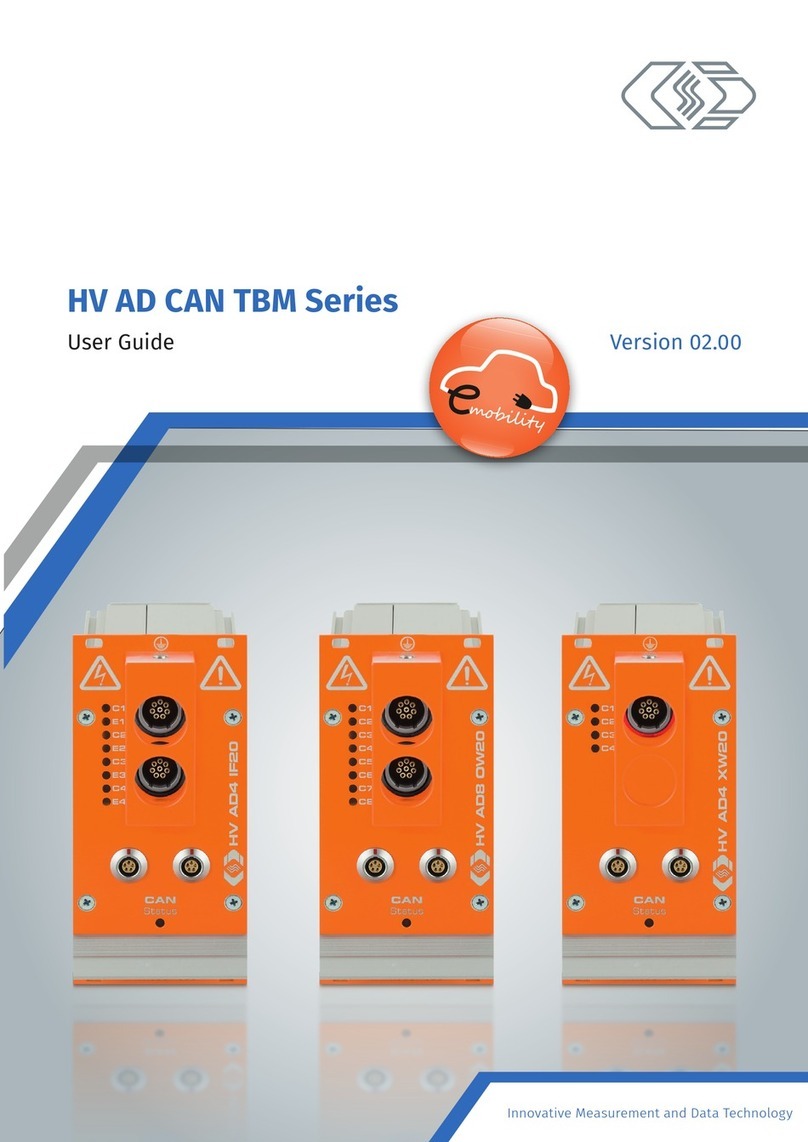
CSM UniCAN 3 User manual

Innovative Measurement and Data Technology
Version 01.00
UniCAN 3
Installation Manual

Installation Manual I Version . //
UniCAN – Copyright
Copyright
All concepts and procedures described in this document are intellectual property of CSM GmbH.
Copying or use by third parties without the written permission of CSM GmbH is strictly prohibited.
This document is subject to change without notice.
Trademarks
All trademarks mentioned in this document are the property of their respective owners.
Product disposal/recycling
If this symbol (crossed-out wheeled bin) appears on the device, this means that the European
Directive //EU applies to this device.
The correct disposal of old equipment will protect the environment and people from possible
negative consequences.
Become familiar with local regulations for separate collection of electrical
and electronic equipment.
Follow local regulations and do not dispose of old equipment with house-
hold waste.
Contact information
CSM offers support for its products over the entire product life cycle. Updates for the
individual components (e.g. documentation, configuration software and firmware) are made
available on the CSM website. To keep up to date, it is therefore recommended that you
check the download area of the CSM website for updates at least once a month.
Germany (headquarters) USA
Address CSM Computer-Systeme-
Messtechnik GmbH CSM Products, Inc.
Raiffeisenstrasse
Filderstadt, Germany Opdyke Court, Suite
Auburn Hills, MI
Phone
Email info@csm.de info@csmproductsinc.com
Website www.csm.de www.csmproductsinc.com

UniCAN –
Installation Manual II Version . //
UniCAN – Contents
Contents
General information. . . . . . . . . . . . . . . .
. Liability disclaimer . . . . . . . . . . . . .
. Warranty and exclusion of warranty . . . . . . .
. Electromagnetic compatibility (EMC) . . . . . . .
Safety instructions . . . . . . . . . . . . . . . .
. General safety instructions . . . . . . . . . .
. Obligations of the operator . . . . . . . . . .
Installing the device. . . . . . . . . . . . . . . .
. General information . . . . . . . . . . . . .
. Connection overview. . . . . . . . . . . . .
. LED and status indicators . . . . . . . . . . .
. Installation . . . . . . . . . . . . . . . .
3.4.1 Check before connection . . . . . . . . . . 7
3.4.2 Connecting the device . . . . . . . . . . . 7
3.4.3 Inserting CF card and SIM card . . . . . . . . 7
3.4.4 Putting device into operation . . . . . . . . . 8
. Replacing the battery . . . . . . . . . . . .
. Connectors . . . . . . . . . . . . . . . .
3.6.1 Power supply and Ethernet. . . . . . . . . . 9
3.6.2 CAN interface . . . . . . . . . . . . . . 10
3.6.3 Digital inputs and outputs . . . . . . . . . .11
3.6.4 Antenna connectors . . . . . . . . . . . .12

UniCAN – General information
Installation Manual Version . //
1 General information
1.1 Liability disclaimer
This installation manual and other documents are part of the product and contain important informa-
tion for its safe and efficient use. To maintain the high quality level the product is continuously being
developed, which may result in the product’s technical details changing at short notice. As a result, the
contents of this documentation may differ from the technical specifications of the product. No claims
against the manufacturer can therefore be derived from the contents of the product documentation.
CSM GmbH is not liable for technical or editorial errors or missing information.
CSM GmbH assumes no liability for damage resulting from improper use of the product and/or
non-observance of the product documentation, in particular the safety instructions.
→ See chapter 2 “Safety instructions”.
1.2 Warranty and exclusion of warranty
The warranty covers the safety and functionality of the product within the warranty period. Excluded
from the warranty are claims based on possible consequential damages caused by malfunction or
non-function of the product.
The warranty shall become invalid if:
fthe product is handled improperly,
fthe product is changed,
fthe information in the documentation belonging to the product is not observed,
fthe product is operated with accessories or parts which are not explicitly approved for operation
by the manufacturer of the product.
→ See chapter 2 “Safety instructions”.
1.3 Electromagnetic compatibility (EMC)
The manufacturer declares that UniCAN data loggers are in conformity with the
requirements of EU Directive //EU.
NOTE!
i
To ensure that operation is as trouble-free as possible, appropriately suitable cables
must be used for connection.
)Use only shielded cables for the serial data line outside metal housings.
)Use only suitable shielded and twisted pair wires for the CAN bus.

UniCAN – Safety instructions
Installation Manual Version . //
2 Safety instructions
This chapter contains important safety information. Please read the following sections carefully.
2.1 General safety instructions
All relevant safety standards were taken into account during development and manufacturing of
the device. The product is produced in accordance with the requirements of an ISO Quality
Management System.
WARNING!
Connecting a UniCAN device to an existing CAN bus system (e.g. vehicle or automation
system) can affect the behaviour of the CAN bus.
Improper handling of a CAN bus system can be a danger to life for persons and cause
damage to property.
)Read the accompanying technical documentation before putting into operation.
)Observe relevant safety guidelines.
)Only suitable device versions may be connected (bus type and protocol).
)Ensure that the measurement configuration is suitable.
)Ensure that the work is only carried out by qualified and trained personnel.
2.2 Obligations of the operator
The operator must ensure that only qualified and authorized personnel are entrusted with handling
the product. This applies to assembly, installation and operation.
In addition to the product’s technical documentation, the operator may also have to provide operat-
ing instructions in accordance with the Occupational Safety and Health Act and the Ordinance on the
Use of Working Materials.

UniCAN – Installing the device
Installation Manual Version . //
3 Installing the device
3.1 General information
UniCAN data loggers are used to record measurement data available over a CAN bus. They can be
used for diagnostic purposes and for the long-term monitoring of systems and vehicles. UniCAN
data loggers are available in different versions. Each of these versions is also offered with isolated
CAN interfaces.
Part No. CAN Digital I/O USB LAN GPS WWAN WLAN
ART
✔ ✔
✘
ART LTE
ART LTE_US
ART
✘
ART LTE
ART LTE_US
ART
✘
ART LTE
ART LTE_US
[✔] included [] optional [✘] not available
Tab. 3-1: Product versions (excerpt)
A complete UniCAN system consists of the following components:
fUniCAN 3 with firmware and CF card as storage medium fK212 power cable
fCSMuniconf PC software fK201 splitter cable
fCSMdataconv PC software (optional) fK204 DigIO cable
fSIM card (optional) fK213 Ethernet adapter cable (opt.)
fAntennas (optional) fUSB cable (optional)
3.2 Connection overview
② ③ ④ ⑤ ⑥ ⑦ ⑧ ⑨ ⑩⑥① ③
⑪ ⑫ ⑬
Fig. 3-1: UniCAN 3, full expansion stage: connectors front and rear side
①Status display ⑦Power supply, Ethernet
②Button for status display ⑧USB . OTG
③Network LED ⑨Digital I/O
④CF card slot ⑩CAN interfaces
⑤SIM card slot ⑪WLAN antenna
⑥Status LED ⑫LTE antenna (UMTS/EDGE/GPRS)
⑬GPS antenna (GLONASS/BeiDou/Galileo)

UniCAN – Installing the device
Installation Manual Version . //
3.3 LED and status indicators
The UniCAN data logger features two LEDs on
the front and back with the exact same function:
fThe network LED (③) indicates the trans-
mission status.
fThe status LED (④) indicates the measure-
ment, operating and card access status.
Color codes of the network LED
LED Meaning
Color Status
—off Not ready (network module not switched on)
green blinking Not ready (network module booting up)
green continuously lit Idle, network module running, no activity
orange/green blinking Activity (status indicator: states . through .)
red continuously lit Error state or firmware update in progress
Tab. 3-2: Color codes for transmission (network LED)
Color codes of the status LED
LED Meaning
Color Status
—off Device not supplied with power or not switched on
green continuously lit Idle, no card inserted/detected or no card access
orange/green blinking Activity (card access)
red continuously lit Error state or firmware update in progress
Tab. 3-3: Color codes for measurement (status LED)
There is also a -digit, -segment display on the front of the UniCAN (①). This display supplements
the two LEDs and is used for visualization of device status and error codes. The location of a dot (⑤)
determines which display is currently active.
fIf the left-hand dot is lit up, the transmission status is being indicated (network LED).
fIf the right-hand dot is lit up, the measurement status is being indicated (status LED).
The display is automatically switched on for seconds after the device is restarted or for seconds
if the status changes. If the display is inactive, pressing the button(②) initiates display of the
measurement status (for seconds). Pressing the button again switches between the display for
measurement and transmission (and lights the display for another seconds).
All possible indications and status values are listed in the following.
② ③ ④①
⑤
Fig. 3-2: UniCAN 3: LED and status indicators, front side

UniCAN – Installing the device
Installation Manual Version . //
Status values of the network LED
Status indications for upload task
. Waiting for available resources
. Establishing network connection
. Writing SOM file
. Searching for updates (immediate)
. Uploading data
. Completing updates
. Searching for updates (delayed)
. Terminating network connection
. Transmitting results
. Error occurred while accessing the modem
. Error occurred while accessing the SIM card
. Pin error occurred
. PUK required
. Error occurred while connecting with PPP
. Error occurred during server login
. Error occurred while reading from server
. Error occurred while writing to server
. Checksum error occurred (FTP)
. Invalid transport configuration
. Resource occupied
. Unspecified connection error
. Error occurred while setting the modem access method
. Non-specified download error occurred
. Upload was canceled
. Invalid host definition
. Internal upload task error occurred
. WLAN license missing
. Incorrect network settings of the transport configuration
Status indications for PC connection
. Connected via USB
. USB data transmission to CSMuniconf active
. Internal error
Other indications
n.r Not ready (boot process)
o.n Idle (no activity)
r. Service mode activated
u.b “uboot” activated
u.F Updating firmware
Tab. 3-4: Status values for transmission (network LED)

UniCAN – Installing the device
Installation Manual Version . //
Status values of the status LED
Static errors affecting evaluation of the CF card content
. Invalid compact flash card
. Invalid DFAT-STFS container
. Invalid REC version, incompatible configuration format
. Invalid firmware version, firmware too old
. Invalid device option, incorrect device type
. Invalid transport configuration
. Invalid measurement configuration
. Required license not available
Dynamic errors affecting the measurement currently in progress
. Protocol error (e.g. initialization of the ECU not possible)
. CAN bus error detected
. CAN bus message lost
. Card FIFO overflow
. Internal system error occurred
Other indications
--. Idle mode, no card inserted or detected
on. Everything OK (measurement running, no errors detected)
uF. Updating firmware
Tab. 3-5: Status values for measurement (status LED)
Example
In Fig. -, the orange/green flashing network LED (③) indicates activity. A continuously lit green
status LED (④) indicates idleness, as a memory card is not inserted.
A push of the button (②) activates the status indicator (①). “--.” appears as status value of the
measurement(⑤) and confirmation of idle mode (see Tab. -). Pressing the button again calls up “.”
as status of the transmission (⑥), i.e. the data logger attempts to establish a network connection
(see Tab. -).
② ③ ④①
⑤
⑥
Fig. 3-3: UniCAN 3: example showing LED and status indicators on front

UniCAN – Installing the device
Installation Manual Version . //
3.4 Installation
NOTE!
i
Cable shield, housing and ground of the connections are connected directly to the
power supply ground (Power GND, negative pole to ground).
)Incorrect cabling may cause damage to the device.
)When connecting the device, ensure correct polarity and supply voltage.
→ Please also observe chapter 3.6.2 “CAN interface”.
NOTE!
i
Trouble-free functioning and electrical safety can only be ensured if the product is
installed properly.
)Ensure proper installation.
)The device may only be operated within the working environment specified.
→ See also “UniCAN 3” datasheet.
NOTE!
i
Observe EMC regulations.
)The device and its antennas must be kept more than cm away from the human
body during operation.
)For compliance with FCC regulations, the antenna gain may not exceed dB.
i
Information on the current status of device and associated software can be found
in the “readme.txt” file of the CSMuniconf software installation package. The most
current version of CSMuniconf can be found in the download area of the CSM website.
→ See: https://s.csm.de/en-uc
.. Check before connection
)Ensure that the cables required for proper connection are used (connection to power supply is
usually made using the K cable).
)Ensure that polarity and supply voltage are correct.
→ See also chapter 3.6.1 “Power supply and Ethernet”.
)Comply with the specifications for all connected components.
.. Connecting the device
)Attach CAN connections of the device to the CAN bus system.
)Connect device to power supply.
.. Inserting CF card and SIM card
3.4.3.1 Opening the hinged cover
The hinged cover of the device can be opened as follows:
)Press against the hinge lightly from
below (see Fig. -).
The lock is released, the hinged
cover opens.
)Open the hinged cover fully as
shown in Fig. -.
Fig. 3-4: Releasing the lock Fig. 3-5: Opening hinged cover

UniCAN – Installing the device
Installation Manual Version . //
3.4.3.2 Inserting a CF card
)Insert a formatted and configured CF cardinto the card slot.
NOTE!
iData storage on CF cards ensures a high degree of security against data loss. To avoid
potential data loss, the CF card should not be inserted or removed during operation.
3.4.3.3 Inserting a SIM card (model-dependent)
i
Only certain versions of the UniCAN data logger feature a built-in mobile commu-
nications modem (see Tab. -). A SIM card only needs to be inserted if mobile data
transmission is desired. The UniCAN must also have a corresponding transport
configuration and be connected to a suitable antenna (see chapter ..).
With the UniCAN , the SIM card (in mini-SIM format) is first
inserted into a card holder and then into the card slot. The
card holder is released by pressing the button to the right
of the card slot. We recommend using a pointed object,
such as a pen, for this purpose.
)Insert SIM card into the card holder.
)Push card holder into the slot with the SIM card facing
upward until it snaps into place (seeFig. -).
NOTE!
iWhen inserting the SIM card into a UniCAN , make sure that the card holder is inserted
into the slot with the SIM card facing upward. If the card holder is inserted with the
SIM card facing downward, the card can fall out of the holder and damage the device.
.. Putting device into operation
)Switch on the device or connect it to the power supply.
The start of measurement is indicated by “on.” on the -segment display and occurs immediately
after switch-on.
The network module is started approx. seconds later, indicated by “o.n” on the -segment display.
Connection establishmentthen begins, indicated by statuses “.” through “.”.
)If none of the LEDs are lit up red, everything is ready and in order. If this is not the case, check the
status values.
→ See chapter 3.3 “LED and status indicators”.
A configuration can either be transmitted from the PC to a CF card inserted into a card reader or directly to a
CFcard in the data logger over a USB connection.
A connection is only established if the data logger has a transport configuration involving data transmission
over mobile communications or WLAN.
3.5 Replacing the battery
NOTE!
i
UniCAN data loggers are equipped with a built-in lithium battery which can be
replaced by CSM if necessary.
)Send the device to CSM for service if the battery is no longer working.
Fig. 3-6: Inserting SIM card with card holder

UniCAN – Installing the device
Installation Manual Version . //
3.6 Connectors
.. Power supply and Ethernet
UniCAN data loggers are designed for an operating voltage of V DC (– ) to V DC ( ). The
connection to power supply and Ethernet is made using a -pole LEMO0B socket on the back of the
housing (see Fig. -, ⑦“Power supply, Ethernet”).
NOTE!
i
The shield and GND of a signal line, as well as the housing of the data logger, are elec-
trically connected to the power GND of the supply line.
There is a risk of damage from short-circuit current or compensating current.
)Never connect the supply voltage to shield, GND or housing.
)Ensure that shield, GND and housing are held on the same potential.
Image Pin Signal Description
1
2
3 4
5
6
7
(Power ) Power supply, plus
(Ignition) Control signal for switching the device on and off
TxN_P Ethernet transmitter, plus
TxN_N Ethernet transmitter, minus
RxN_P Ethernet receiver, plus
RxN_N Ethernet receiver, minus
(Power GND) Power supply, ground
Housing Shield Cable shield
Tab. 3-6: “Power supply, Ethernet” socket pin assignment (back view of the device)
The following table shows the assignment of the signals to the wire colors for a K cable (LEMO0B,
-pole to open cable end):
Signal Description Wire color
(Power ) Power supply, plus Red
(Power GND) Power supply, ground Black
(Ignition) Control signal for switching the device on and off Yellow
Tab. 3-7: K212 signal cable: signal to wire color assignment
NOTE!
i
To prevent data loss in case of a sudden interruption of the power supply, we recommend
switching the device on and off with the ignition signal (terminal ). Please use the
following connection:
1
2
3 4
5
6
7
Ignition on/off
(terminal )
Steady plus
(terminal ) Ground
(terminal )
If no ignition signal is available, or the device is to be switched on and off by Wake-on-CAN
or a set alarm instead, use the following connection:
1
2
3 4
5
6
7
Ground (terminal)
or unconnected
Steady plus
(terminal ) Ground
(terminal )
Make sure that the device switches itself off using a suitable configuration while it is
still supplied with power (steady plus) to avoid data loss.

UniCAN – Installing the device
Installation Manual Version . //
i
If only a switched power supply is available, we recommend additional buffering
using the CSM power control module (PCMM).
For additional information, please contact the sales department.
.. CAN interface
D-SUB-HD sockets, 15-pole (device)
Depending on the version, the UniCAN features up to three -pole D-SUB-HD sockets (see Fig. -,
⑩“CAN interfaces”, from left to right: CAN –, CAN –, CAN –). The pin assignment of the first
(left-hand) socket is as follows, whereas the other two sockets correspond to the same scheme:
Image Pin Signal Description
1
11
5
15
610
CANH CAN High
CANH CAN High
CANH CAN High
CANL CAN Low
not assigned —
CANL CAN Low
CANL CAN Low
CANL CAN Low
not assigned —
CANH CAN High
CANGND CAN Ground
CANGND CAN Ground
CANGND CAN Ground
CANGND CAN Ground
not assigned —
Tab. 3-8: Pin assignment of the first (left-hand) 15-pole D-SUB-HD CAN socket (back view of device)
D-SUB plug, 9-pole (K201 cable)
On the CSM K cable, four CAN connections are routed on separate -pole D-SUB plugs with a CiA-
compatible pin assignment.
Image Pin Signal Description
1 5
6 9
not assigned —
CAN L CAN Low
CAN GND CAN Ground
not assigned —
Shield Shield / Housing
not assigned —
CAN H CAN High
not assigned —
CAN PWR CAN power (not required)
Tab. 3-9: Pin assignment of a 9-pole D-SUB plug (K201 cable)

UniCAN – Installing the device
Installation Manual Version . //
.. Digital inputs and outputs
The connection to the digital inputs and outputs is made using a -pole LEMO0B socket on the back
of the housing (see Fig. -, ⑨“Digital I/O”).
i
The additional service access connected to this socket is usually not relevant for
customers.
Digital I/O
Image Pin Signal Description
1
2
3 4
5
6
7
DIN/DOUT Digital Input/Output
DIN/DOUT Digital Input/Output
DIN/DOUT Digital Input/Output
DIN/DOUT Digital Input/Output
GND Signal Ground
— Reserved for service access
— Reserved for service access
Housing Shield Shield
Tab. 3-10: Pin assignment of the digital I/O interface (back view of device)
The digital inputs accept voltage levels
of over . V as a logical “” (UIN-High ,
“high” level) and voltage levels below
V as logical “0” (UIN-Low , “low” level).
The input voltage may be within the
range of 0 V to 10 above the supply
voltage of the battery (. UBatt). If the
input voltage is less than .V, the
impedance is M. Otherwise, it is
k. The input voltage levelUIN of
all digital inputs is determined ,
times per second (fSkHz).
A logical “” of the digital output
(UOUT-High , “high” level) corresponds to
an output voltage UOUT-High UBatt – .V,
with an output voltage of up tomA.
With a logical “0” (UOUT-Low , “low”
level), the digital output is connected
with high resistance (k with
UOUT.V and M with UOUT.V)
to the ground (GND), i.e. the voltage
characteristic of UOUT with a logical
“0” of the digital output is primarily
influenced by the connected consumer.
All outputs and the signal ground are
short-circuit proof (DOUTx to GND and GND to UBatt).
UBatt
U [V]
1 V
2.5 V
1.1× UBatt
UBatt
UBatt-1.1 V
UIN-High
UOUT-High
UIN-Low
0
5
3
4
2
1
1 M
220 k
3.8 V 3.8 V
Fig. 3-7: Voltage level and impedance of the digital inputs/outputs

UniCAN – Installing the device
Installation Manual Version . //
.. Antenna connectors
NOTE!
i
Observe EMC regulations.
)The device and its antennas must be kept more than cm away from the human
body during operation.
)For compliance with FCC regulations, the antenna gain may not exceed dB.
i
UniCAN data loggers are available in different versions. Not all device versions
include a mobile communications modem (LTE/UMTS/EDGE/GPRS). Activation of
the WLAN module and the GNSS module (GPS/GLONASS/BeiDou/Galileo) is always
available as an option.
① ② ③
Fig. 3-8: UniCAN 3: back of housing with antenna connectors
①Connection for WLAN antenna RP-SMA socket
②Connection for mobile communications antenna FAKRA socket, code D, bordeaux
③Connection for GPS antenna FAKRA socket, code C, blue
The internal GNSS module also supports GLONASS, BeiDou and Galileo.

All trademarks mentioned are property of their respective owners.
Specifications are subject to change without notice.
CANopen® and CiA® are registered community trade marks of CAN in Automation e.V.
EtherCAT® is registered trademark and patented technology, licensed by Beckhoff Automation GmbH, Germany.
Table of contents
Other CSM Data Logger manuals
Popular Data Logger manuals by other brands
Magna
Magna BluePirat Remote Control Touch Start-up

Inova
Inova FireFly DR31 Quick reference guide
National Instruments
National Instruments NI-DAQ mx CALIBRATION PROCEDURE
Lowell
Lowell MAT-1 Data Logger instructions
Racelogic
Racelogic Performance Box Touch V2 Installing
cloudworks
cloudworks CDS543 user manual
