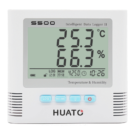
Huato S500 Series User manual

User’s Guide
S500 Series Temperature &
Humidity Data Logger
S500
E-mail: [email protected]
Talk to our sales
and shop online at
www.huato.cn

The information contained in this document is believed to be correct, but HUATO accepts no liability for any errors it contains, and reserves
the right to alter specifications without notice.
HUATO HUATO ELECTRIC CO., LTD.
Toll-Free: 0755-29977605
Customer Service: 0755-29977605
Engineering Service: 0755-29977605
Fax: +86-755-29748856
E-mail: [email protected]
Headquarters:
For Other Locations Visit www.huato.cn

Table of
Contents
Table of Contents
Section
..................................................................................................................................
Page
Section 1 Introduction .....................................................................................
1.1 Features ..............................................................................................
1.2 Applications .........................................................................................
1.3 Data Logger Model ...............................................................................
1.4 S500-EX/TH/ET/DT- USB DataLogger Appearance ............................
1.5 S500-EX/TH/ET/DT-RS485Data Logger Appearance ........................
1.6 LCD Temperature and Humidity Data Logger Screen .........................
1.7 Button function instructions ...................................................................
Section 2 S500-EX/TH/DT- USB Software Installation ........................
2.1 USB Install Driver & Software ..............................................................
2.2 Use of Logpro software ......................................................................
Section 3 S500-EX/TH/ET/DT-RS485 Software Installation ...............
3.1 Use of ToMonitor real-time monitoring software ..................................
3.2 Check the Save File in File List ..........................................................
Section 4 Attention .....................................................................................
4.1 Attention ................................................................................................
4.2 FAQ ....................................................................................................
1
1
1
1
2
3
4
5
6
6
7
10
10
13
16
16
16

• High-end integrated temperature & humidity sensors with original calibration.
• Built-in storage, up to 43,000 groups of temperature & humidity data.
• High accuracy in measuring temperature & humidity.
• Temperature, humidity and time are displayed simultaneously. Easy to operate with buttons.
• Built-in sound and light alarm, triggers when data value exceeds the thresholds. Simple and
elegant appearance, can be placed on the desk or mounted on the wall.
• Easy to use professional analysis software. Multiple data protection mechanism.
Widely used in medicine, electronics, transportation, warehousing, scientific research institutes,
meteorology, professional labs,museums, libraries, meteorological departments, etc.
Section 1 Introduction
1.1 Features
1.2 Applications
1.3 Data Logger Model
1
Introduction
1
Model
Temperature & Humidity
Temperature
Dual Temperature
Measuring
Accuracy
Measuring
Rang
43000
43000
43000
Sensor
type
Dual
External
Internal
External
Internal
External
Internal
External
Internal
External
Internal
External
Internal
External
S500-TH
S500-EX
S520-TH
S520-EX
S580-TH
S580-EX
±0.5℃/± 5%RH
±0.5℃/± 5%RH
±0.3℃/± 3%RH
±0.3℃/± 3%RH
±0.2℃/± 2%RH
±0.2℃/± 2%RH
-20~70℃/ 0~100%RH
-40~85℃/ 0~100%RH
-20~70℃/ 0~100%RH
-40~85℃/ 0~100%RH
-20~70℃/ 0~100%RH
-40~85℃/ 0~100%RH
S500-T
S500-ET
S520-T
S520-ET
S580-T
S580-ET
±0.5℃
±0.5℃
±0.3℃
±0.3℃
±0.2℃
±0.2℃
-20~70℃
-40~85℃
-20~70℃
-40~85℃
-20~70℃
-40~85℃
S500-DT
520-DT
±0.5℃
±0.3℃
-40~85℃
-40~85℃
Record
Volume

1.4 S500-EX/TH/ET/DT- USB Data Logger Appearance
2
Introduction 1
1
2
3
4
5
6
S500 Intelligent Data Logger II
Temperature&Humidity
MENU MAX
MIN OK
LOG
记录 MEM
储存 7
8
91 0 11
11
① LCD Screen
② ON/OFF Button
③ Backlight Button
④ Max or Min value and normal state switch button
⑤ Log ON/OFF
⑥ Hanging hole
⑦ Stand
⑧ S/N
⑨ Reset
⑩ USB
DC 12V

1.5 S500-EX/TH/ET/DT-RS485Data Logger Appearance
Introduction
1
3
11
① LCD Screen
② ON/OFF Button
③ Backlight Button
④ Max or Min value and normal state switch button
⑤ Log ON/OFF
⑥ Hanging hole
⑦ Stand
⑧ S/N
⑨ Reset
⑩ USB
DC 12V
1
2
3
4
5
6
S500 Intelligent Data Logger II
Temperature&Humidity
MENU MAX
MIN OK
LOG
记录 MEM
储存 7
8
91 0 11

1.6 LCD Temperature and Humidity Data Logger Screen
Introduction 1
4
MEM
储存
Icon Explanation
Backlight light
Alarm indicator. When the real-time value of temperature & humidity exceeds
the set upper and lower threshold, an alarm symbol will be displayed
Humidity display
Button lock/unlock
DC 12V external power supply
This symbol shows that the instrument is logging
Storage capacity, 4250 is the number of current records
Battery level indicator. When the area is full black, it indicates that the battery leve
l is sufficient. If it is empty, it means the battery is low and should be replaced
This symbol shows that the instrument has been connected to the computer and
data can be downloaded at this time
This symbol shows that the instrument only displays the upper threshold of the
temperature and humidity alarm value
This symbol shows that the instrument only displays the lower threshold of the
temperature and humidity alarm value
Display year, month and time one by one, 15 seconds for year information,
another 15s for month information, and then 30s for time information
Temperature display
MEM
储存

Put the attached software CD into the CD drive of the computer, find the file. Choose
right driver version according to the operating system:
For Win7, Win8, Win10 - 64 bits operating systems choose "CH341SER[64bit]"
For Win XP; Vista; Win7 - 32 bits operating system choose "CH341SER[32bit]".
Section 2 S500-EX/TH/DT- USB Software Installation
1.7 Button function instructions
2.1 Install USB Driver & Software
2.1.1 Click [CH341SER]
5
Installation and Instruction
2
LOG button, turn logging ON/OFF
MAX/MIN button
Backlight button
Power button
(1) In the non-logging mode (standby), press to enter the logging mode, LOG
indicator and the number of current records will be displayed on the LCD.
(2) In the logging mode, press this button to exit the logging mode, LOG indicator
and the number of current records will disappear.
In normal working mode, press this button to view the maximum/minimum
measurement value and the upper/lower alarm thresholds.
In normal working mode, press this button to turn on/off the backlight.
In the power-off state, click this button to turn on the instrument. In the
power-on state, turn off the logging function first, and then press this
button to turn off the instrument.
Note: Press at the same time to lock/unlock the keys.
After the installation is complete, connect the instrument to the computer through the attached
data cable to check whether the new port number can be found.
The steps to check the new port number are as follows:
2.1.2 Click
2.1.3 Right-click the [My Computer] icon-[Manage
(G)]-[Device Manager]-as shown below:
6
Installation and Instruction
2
Installation
OK
Device
Manager Port
Icon

Note: If the port number cannot be found in the above operation, please shut down the
computer and restart to try it again.
(1) Copy the software folder in the attached CD-ROM to the computer and create a desktop
shortcut. Connect the instrument to the computer when it is turned on.
(2) Run the software, enter the software interface, connect the instrument with USB interface,
click the connection button in the menu bar, and the [Communication Settings] dialog will pop up.
Check the port number under [Computer Management]-[Device Manager]-[Port]. Select the port
number of CH340 or CH341. Set 115200 or 38400 baud rate, click [Confirm] button to connect.
The operation buttons of disconnection, setting, download, delete, etc. will be enabled after
connection established.
2.1.4 Next, double-click [Port (COM and LPT)] to check the port number
like CH340 or CH341 as shown in the figure below:
2.2 Use of Logpro software
Installation and Instruction 2
7
Port
number
Port
number
Port
number

(3) Configuration buttons: Click the button in the menu bar, click the button in the setting
dialog to read the attributes from the instrument, and then perform configuration of the instrument.
Click the button to synchronize with the instrument, the setting parameters will take effect,
otherwise the setting parameters will be ineffective. Click the button to synchronize the
instrument time with the computer time. The instrument must be used after time synchronization.
Installation and Instruction
2
8
Port
number

Name User defined
The instrument's unique serial number, cannot be changed
Sampling interval, range 1-240s
2-86400s, which needs to be greater than the sampling interval
In order to provide flexible calibration, the instrument supports
setting channel one and channel two deviations. The measurement
can be fine-tuned. Decrease when a positive number is entered,
and increase when a negative value is entered. Suggest not to change.
Set the upper and lower alarm thresholds of the sensor. If the
function is turned on, alarms will be triggered when data exceeds
the upper or lower thresholds. Taking a temperature logger as an
example, channel one refers to the temperature of channel one,
and channel two is the temperature of the channel two.
Sampling interval
Log interval
Alarm upper &
lower thresholds
Deviation
SN
(4) Click download - confirm to download all the data from the instrument to the computer, save
automatically and generate reports and data lists automatically.
(5) Click the data list to view the data as followed:
Installation and Instruction 2
9

6) The recorded data can be exported to EXCEL file, click and choose location to save.
It can also be exported as file or picture in format for further processing.
(7) Click the button to delete all data records in the logger.
(8) Click and use Logpro software to print out the analysis chart directly.
(1) Open the file and find the ToMonitor icon, as shown below:
(2) Click login, enter Account: admin; Password: admin
Section 3 S500-EX/TH/DT- USB Software Installation
3.1 Guide of ToMonitor real-time monitoring software
Installation and Instruction
3
10
click ToMonitor

(3) Check the USB port of the computer
(4) Select the correct port accordingly for RS485 data reception
(5) Set the instrument name and fill in the instrument serial number and instrument type settings
1. Select any of the instruments in the upper left corner, after displaying the data, enter required
instrument name and serial number. Click [Add] in the lower right corner to add a new instrument.
Select RS485 as the instrument type.
2. After successfully added, select the new instrument in the upper left corner and click [Properties]
Installation and Instruction 3
11
Port
number

3.Click [Properties] to pop up a dialog, as shown in the figure below.
4.Click [Get Properties], and then click [Sync Properties] after getting the data
5.After completing the above operations, the temperature and humidity data will be uploaded.
Installation and Instruction
3
12
Port
number

(Note: ToClient8 can only be used when ToMonitor is turned on, otherwise connection will fail.)
(1) Run ToClient8 the Huato software file folder as shown below:
3.2 View uploaded data.
Installation and Instruction 3
13
Click ToClient8

(2) Login and connect
(3) Click record query to pop up the following dialog. Select the instrument to be queried
and click [Start Query]
Installation and Instruction
3
14

(4) The following dialog pops up to view the corresponding data.
(5) Click the [View Data] icon to pop up the following dialog to view the real-time data
Installation and Instruction 3
15

Section 4 Precautions
4.1Notes
4.2 Common faults
Installation and Instruction 4
16
• The waterproof index of this logger is IP34. If there is moisture on the case, do NOT perform USB
connection operation to prevent the electronic circuit from being short-circuited with water, which
may damage the instrument.
• The logger adopts ABS engineering fireproof plastic shell, please prevent the device from corrosion
of acid and alkali chemicals.
• If a malfunction occurs, it must be repaired by an authorized professional. Please do NOT repair or
modify it yourself.
• The 9V alkaline battery equipped with this instrument cannot be recharged or short-circuited, otherwise
it may be dangerous. Please dispose of used batteries properly to protect the environment.
(1) The LCD display becomes low lighted
Cause: The battery power is low or the environment temperature is too low or too high.
Solution: replace the battery. If it is caused by the environment temperature, please take the
logger out of the environment immediately to avoid damage to the logger.
(2) The LOG indicator disappears
Reason: When the battery power is too low, there will not be enough power to maintain the
recording function on the logger.
Solution: replace the battery.
(3)The FULL symbol appears at the bottom of the display, indicating that the storage of the
logger is full, which is normal
Solution: Connect the logger to the software, and delete the full data.
Other manuals for S500 Series
1
Table of contents
Other Huato Data Logger manuals

Huato
Huato S100 Series User manual

Huato
Huato HE17 Series User manual

Huato
Huato S400W Series User manual

Huato
Huato HE173 User manual

Huato
Huato S500 Series User manual

Huato
Huato S220-T8 Series User manual

Huato
Huato S1500 Series User manual

Huato
Huato S300-E User manual

Huato
Huato S1500 Series Quick start guide