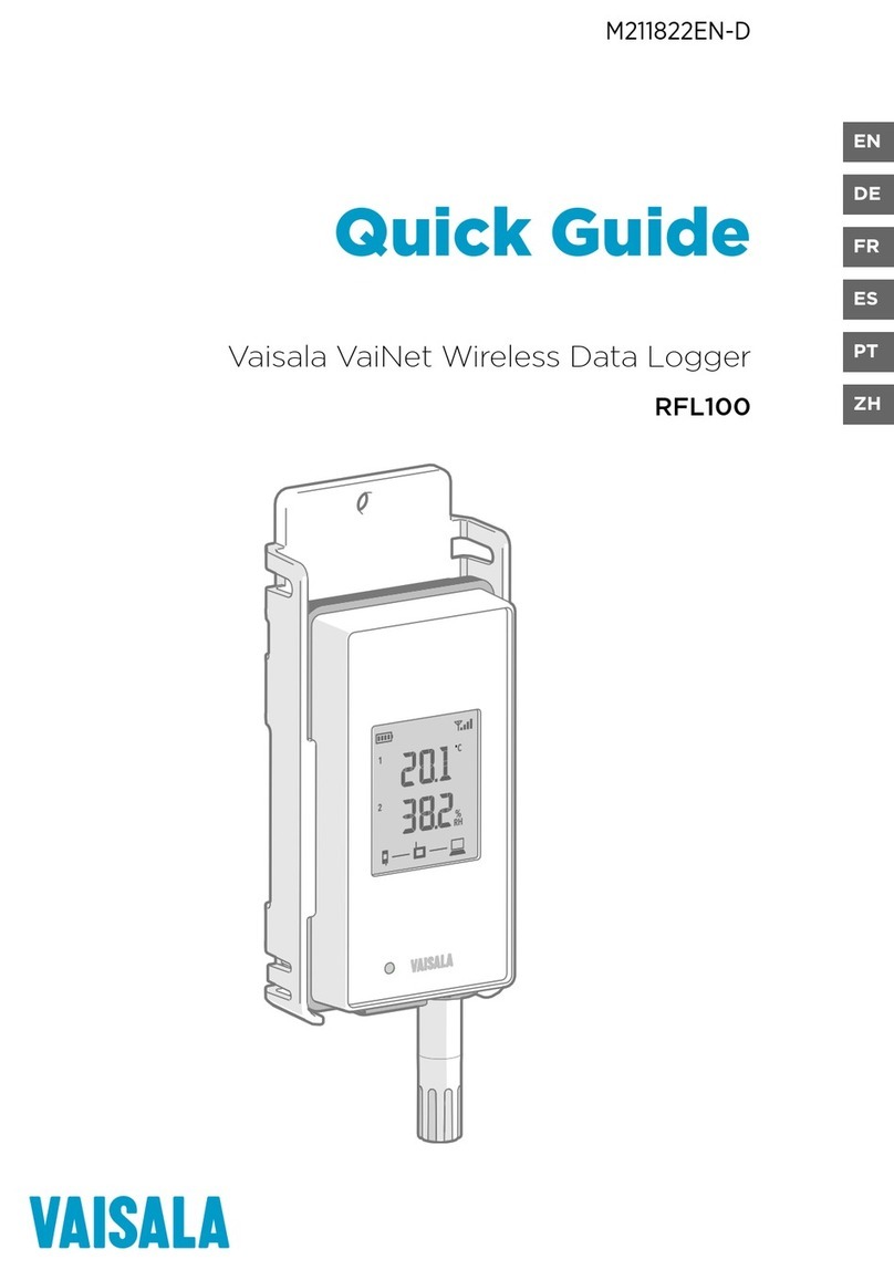
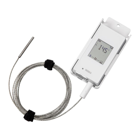
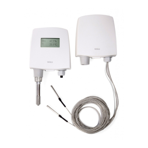
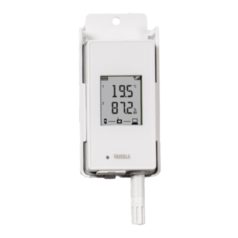
Vaisala VaiNet RFL100 User manual

EN
DE
FR
ES
PT
JA
ZH
M211822EN-G
Quick Guide
Vaisala VaiNet Wireless Data Logger
RFL100

PUBLISHED BY
Vaisala Oyj
Vanha Nurmijärventie 21, FI-01670 Vantaa, Finland
P.O. Box 26, FI-00421 Helsinki, Finland
+358 9 8949 1
Visit our Internet pages at www.vaisala.com.
© Vaisala 2021
No part of this document may be
reproduced, published or publicly
displayed in any form or by any means,
electronic or mechanical (including
photocopying), nor may its contents be
modified, translated, adapted, sold or
disclosed to a third party without prior
written permission of the copyright holder.
Translated documents and translated
portions of multilingual documents are
based on the original English versions. In
ambiguous cases, the English versions are
applicable, not the translations.
The contents of this document are subject
to change without prior notice.
Local rules and regulations may vary and
they shall take precedence over the
information contained in this document.
Vaisala makes no representations on this
document’s compliance with the local
rules and regulations applicable at any
given time, and hereby disclaims any and
all responsibilities related thereto.
This document does not create any legally
binding obligations for Vaisala towards
customers or end users. All legally binding
obligations and agreements are included
exclusively in the applicable supply
contract or the General Conditions of Sale
and General Conditions of Service of
Vaisala.
This product contains software developed
by Vaisala or third parties. Use of the
software is governed by license terms and
conditions included in the applicable
supply contract or, in the absence of
separate license terms and conditions, by
the General License Conditions of Vaisala
Group.
This product may contain open source
software (OSS) components. In the event
this product contains OSS components,
then such OSS is governed by the terms
and conditions of the applicable OSS
licenses, and you are bound by the terms
and conditions of such licenses in
connection with your use and distribution
of the OSS in this product. Applicable OSS
licenses are included in the product itself
or provided to you on any other applicable
media, depending on each individual
product and the product items delivered
to you.

Table of contents
English.............................................................................................................................................5
Deutsch........................................................................................................................................ 27
Français.........................................................................................................................................51
Español.........................................................................................................................................77
Português................................................................................................................................... 101
日本語.............................................................................................................125
中文................................................................................................................ 149
3

4 M211822EN-G

Setting up RFL100
Start the installation of RFL100 by performing the appropriate setup procedure:
• If you are connecting 1 humidity or temperature probe, see Setup with 1 humidity or
temperature probe (page 5).
• If you are connecting 2 temperature probes using the probe splitter accessory, see Setup
with 2 temperature probes (page 7).
• If you are connecting a carbon dioxide (CO2) probe, see Setup with CO₂ probe
(page 9).
At least viewLinc Enterprise Server version 5.0 is required for
connecting RFL100 data loggers. Setup instructions include additional firmware
and hardware requirements for using RFL100 with 2 temperature probes, or a
CO2probe. Make sure the components of your viewLinc Monitoring System are
updated to the required levels.
CAUTION!
When you switch on an RFL100 that has not been accepted to any viewLinc
system yet, it starts to scan for VaiNet access points that are in installation mode.
RFL100 will connect to the access point with the best signal strength, and wait to
be accepted by the administrator of the viewLinc Enterprise Server. Make sure the
access point(s) are installed and in installation mode before starting to set up
RFL100 data loggers.
Setup with 1 humidity or temperature probe
1
2
3
1Power switch.
2Transport protection cap. Remove
after installation is complete.
3Latch of the battery cover.
1. If any cable is connected to the service port of the data logger, disconnect it.
2. Open the battery cover of the data logger.
3. Make sure the power switch is in the O position.
5
ENGLISH

4. If a probe is not already connected to the data logger, connect it now:
• To connect a probe directly to the data logger, first align the orientation mark on the
probe with the line above the probe connector. Then push the probe in all the way, do
not rotate.
• To connect a probe using an extension cable, use an accessory cable that has been
designed for RFL100. Insert the cable connector in the same way as a probe, and then
connect the probe to the cable. Note that HMP110 and HMP110T probes must always
be connected using a cable as they do not mechanically lock into the data logger
when the battery cover is closed.
5. Move the power switch to the On position.
6. Close the battery cover of the data logger. Push the latch down until you hear a click. If
the cover does not close easily, push the probe (or extension cable) in and try again.
7. Look at the display and wait for the data logger to start up. Then verify the status:
• Data logger shows the word NEW on each aected channel when it detects that a
probe has been changed 1). The text is shown for a few seconds, after which the
display shows the measurement reading(s).
Figure 1 Detection of a new RH + T probe
• If dashes "- - -" are shown instead of measurement readings, check that the probe is
properly connected. It is possible to disconnect the probe or cable by pulling it with
the battery cover open.
• Battery indicator should show full batteries .
• There should be no error codes shown. If there are, see Error codes (page 23).
1) This feature is included in RFL100 firmware version 1.2.0 and newer.
6 M211822EN-G

Setup with 2 temperature probes
1
23
5 6
7
4
1Power switch
2Probe splitter
3Latch of the battery cover
4Instruction label with short version of this setup instruction
5Probe connectors of the probe splitter
6Temperature probes
7Numbering labels for TMP115 probes (included in the probe mounting accessories)
• Two temperature-only probes of following models: HMP110T, HMP115T and
TMP115 (any combination)
• Probe splitter M8 (Vaisala item code CBL210834)
• Optional: probe extension cable(s)
To support operation with two temperature probes, the RFL100
data logger must have firmware version 1.2.0 or higher. Additionally, make sure
the following components of your viewLinc Monitoring System are updated to at
least the following firmware and software levels:
• AP10 firmware version 3.0
• viewLinc 5.0.2
CAUTION!
You must follow the procedure below to set up RFL100 with the
probe splitter. The procedure includes steps to label the probes to make it easy
to identify the channel assignment later. You can also use the info mode of the
RFL100 to check which probe serial number is connected to which channel.
For more information on the info mode, see RFL100 User Guide (M211861EN).
CAUTION!
7
ENGLISH

1. If any cable is connected to the service port of the data logger, disconnect it.
2. Open the battery cover of the data logger.
3. Make sure the power switch is in the O position.
4. If the probe splitter is not yet connected to the data logger, connect it:
a. If a probe or cable is currently connected to the probe connector, pull it straight out
without rotating it.
b. Align the orientation mark on the probe splitter with the line above the probe
connector. Push the probe splitter straight in all the way, do not rotate.
5. Connect the first temperature probe to the probe splitter, using an extension cable if
necessary. The first connected probe will be assigned to channel 1.
6. Move the power switch to the On position.
7. Look at the display and wait for the data logger to start up. You should see the word NEW
on channel 1 for a few seconds, after which it is replaced by the temperature reading.
8. Attach a label with number 1 to the probe you just connected. If you are using TMP115
probes, use the included probe labels. Connect the label to the thin cable between the
probe body and the sensor tip.
9. Move the power switch to the O position.
10. Connect the second temperature probe to the probe splitter, using an extension cable if
necessary.
11. Move the power switch to the On position.
12. Look at the display and wait for the data logger to start up. You should see the word NEW
on channel 2 for a few seconds, after which it is replaced by the temperature reading.
13. Attach a label with number 2 to the probe you just connected.
8 M211822EN-G

14. Look at the display:
• If dashes "- - -" are shown instead of measurement readings, check that the probe and
probe splitter are properly connected. It is possible to disconnect the probe splitter
accidentally by pulling it with the battery cover open.
• Battery indicator should show full batteries .
• There should be no error codes shown. If there are, see Error codes (page 23).
15. Close the battery cover of the data logger. Push the latch down until you hear a click. If
the cover does not close easily, push the probe splitter in and try again.
Once the data logger has been set up for two temperature probes using the
probe splitter, it requires a factory reset before it can be set up for one-probe
mode or operation with a CO2probe.
For the factory reset procedure, see RFL100 User Guide (M211861EN).
Setup with CO₂ probe
1
3
2
6
7
8
4
5
1DC power supply with micro-USB connector
2Power supply connection to service port
3Electronics housing of the Probe Splitter M8/M12 accessory and its magnetic holder
4Humidity or temperature probe
5M8 connector of the probe splitter
6GMP251 CO2probe
7Probe support accessory
8M12 connector of the probe splitter
9
ENGLISH

• GMP251 CO2probe
• Probe splitter M8/M12 (item code CBL211050)
• DC power supply with micro-USB connector
• Optional: any supported humidity or temperature probe
• Optional: probe extension cable(s)
To support operation with a CO2probe, the RFL100 data logger
must have firmware version 1.4.0 or higher, and must be manufactured after July
2021. Additionally, make sure all AP10 access points at the location of use have
firmware version 4.0.0.
CAUTION!
External power supply is a requirement for operating the data logger with a CO2
probe. Batteries are used as a backup power source if the external power fails.
Lithium batteries are recommended as they provide a longer backup time, but
even with lithium batteries the operation time is limited in CO2mode (typically at
least 12 hours). The data logger will show the error code Err 106 if it operates in
CO2mode without a power supply.
1. If any cable is connected to the service port of the data logger, disconnect it.
2. Open the battery cover of the data logger.
3. Make sure the power switch is in the O position.
4. Verify that the data logger has lithium batteries (type FR6) inserted. Replace the batteries
if necessary.
5. If the probe splitter M8/M12 is not yet connected to the data logger, connect it now:
a. If a probe or cable is currently connected to the probe connector, pull it straight out
without rotating it.
b. Align the orientation mark on the probe splitter with the line above the probe
connector. Push the probe splitter straight in all the way, do not rotate.
You can also use a probe extension cable between the data logger and
the probe splitter.
6. Connect the CO2probe to the M12 connector of the probe splitter, using a suitable
extension cable if necessary.
7. Optional: connect the temperature or humidity probe to the M8 connector of the probe
splitter, using a suitable extension cable if necessary. If you do not connect a probe to the
M8 connector, make sure the connector is not inserted inside an incubator, for example.
8. Connect the micro-USB connector of the power supply to the service port of the data
logger, and connect the power supply to a wall socket.
9. Move the power switch to the On position.
10 M211822EN-G

10. Look at the display and wait for the data logger to start up. The word NEW is shown for
channels where a new probe has been connected. Note that the CO2probe is always
connected on channel 3.
CO2measurement shows dashes "- - -" while waiting for the CO2probe to warm up. If
dashes are not replaced by measurement readings within 30 seconds, check that the
probe(s) and probe splitter are properly connected. It is possible to disconnect the probe
splitter accidentally by pulling it with the battery cover open.
11. Check that:
• Battery indicator shows full batteries .
• There are no error codes shown. If there are, see Error codes (page 23).
12. Close the battery cover of the data logger. Push the latch down until you hear a click. If
the cover does not close easily, push the probe splitter in and try again.
Once the data logger has been set up in CO2probe mode, it requires a factory
reset to allow it to be set up for non-CO2operation. For the factory reset
procedure, see RFL100 User Guide (M211861EN).
11
ENGLISH

Mounting RFL100
A
C
B
D
30 [1.18]
Ø 6 [0.24]
mm
[in]
68 [2.65]
Figure 2 RFL100 mounting methods
AMounting with screws. Screws and wall plugs are included with the data logger.
BMounting with a hook (hook not included)
CMounting with cable ties. Cable ties are included with the data logger.
DMagnetic mounting (with optional magnetic mounting bracket)
12 M211822EN-G

1. Select a suitable mounting location. A good location is easily accessible, protected from
water and condensation, and remains within the operating temperature range of RFL100:
• +2 ... +60 °C (+35.6 ... +140 °F) with alkaline batteries
• −20 ... +60 °C (−4 ... +140 °F) with lithium batteries
If you need to measure a wider temperature range, use a HMP110 or TMP115
probe and connect it using an extension cable. This way you can leave the
data logger in an environment that is suitable to its specification.
2. Attach the mounting bracket using one of the mounting methods shown in Figure 2
(page 12). Orient the bracket vertically so that the probe or extension cable points down
after installation. Do not attach RFL100 without the mounting bracket.
If you are mounting the data logger higher than 2 m (6 ft) or in
a location where it would pose a hazard if dropped, ensure the mounting
bracket is securely fixed with screws or cable ties.
CAUTION!
3. Slide the logger into the mounting bracket from the top, with the probe or cable pointing
downward.
4. Peel o the protective film from the display and remove the yellow transport protection
cap from the probe.
5. If the probe(s) are connected using an extension cable or a probe splitter, mount the
probes in the desired measurement locations and secure the cable(s) using the included
accessories.
6. Recommended: Apply location labels to the mounting bracket and RFL100 according to
your installation plan and company policy.
13
ENGLISH

Mounting probes
Probe holder for Ø 12 mm probes
1
2
3
Figure 3 Probe holder for Ø 12 mm probes
1Holes for attaching the holder with
screws (screws not included)
2Magnet
3Probe attachment
The probe holder is a versatile mounting accessory for securing Ø 12 mm diameter cable
mounted probes. One probe holder is included in the RFL100 data logger package for each
applicable cable mounted probe. Additional probe holders are available as an accessory
(Vaisala item ASM213382SP, includes 5 probe holders).
Figure 4 HMP110 probe in the probe holder
To attach the probe, simply press the body
of the probe into the probe attachment.
HMP115 and TMP115 probes have a groove
that locks the probe in the holder when it
is centered in the probe attachment.
14 M211822EN-G

Probe support accessory
Probe support accessory is included when the data logger is purchased with a GMP251 CO2
measurement probe. In addition to providing a versatile attachment for GMP251, the included
probe support has attachments for a Ø 12 mm probe and the sensor tip of the TMP115 probe. It
also provides sucient separation between the probes to prevent the mild heating eect of
the GMP251 from aecting the measurement of the other probe. For this reason, it is best not
to attach the GMP251 to a second probe using a cable tie, for example.
A
C
B
Figure 5 Probe support accessory mounting options
AMounting through a hole using the screw-on attachment part
BMounting using reusable fastener strips
CMounting with screws and wall plugs
15
ENGLISH

Mounting HMP110 probes
HMP110 is a robust stainless steel probe for humidity and temperature measurement in
demanding conditions. Suitable for measurement inside chambers, fridges, and freezers in
temperature range -40 ... +80 °C (-40 ... +176 °F). Must be connected using a cable, as the
probe is not designed to be integrated with RFL100 housing. Probe diameter 12 mm (0.47 in).
2 31
Figure 6 HMP110 probe
1M12×1 thread for through-wall installation using mounting nuts.
2Attach from this area using probe holder ASM213382 or cable tie.
3Sensor protection filter. Do not attach from this area.
Mounting HMP115 probes
HMP115 is a general purpose humidity and temperature measurement probe. It is designed to
be integrated with the RFL100 housing for minimum footprint, but can be connected using a
cable as well. Operating temperature range −40 ... +60 °C (−40 ... +140 °F).
3 421
Figure 7 HMP115 probe
1If using a probe holder, align it to this groove.
2Plastic sleeve that locks the probe in place when integrated with RFL100. Diameter
14 mm (0.55 in) at this point.
3Attach from this area if using a cable tie. Diameter 12 mm (0.47 in) at this point.
4Sensor protection filter. Do not attach from this area.
16 M211822EN-G

Mounting TMP115 probes
TMP115 is a wide-range temperature-only probe for measurement in extreme conditions. The
probe body can be integrated with RFL100 or connected using a cable. The sensor tip is
permanently connected to the probe body with a thin cable. Available as 50 cm (1 ft 7.7 in) and
3 m (9.8 ft) long versions.
4 5321
Figure 8 TMP115 probe
1If using a probe holder, align it to this groove.
2Plastic sleeve that locks the probe body in place when integrated with RFL100. Diameter
14 mm (0.55 in) at this point.
3Probe body with measurement electronics. Attach from this area if using a cable tie.
Diameter 12 mm (0.47 in) at this point. Operating temperature range
−40 … +60 °C (−40 … +140 °F).
4Sensor cable. Do not cut or bend into a tight loop. Numbering labels included with the
probe splitter accessory are designed to be attached to this cable.
5Sensor tip, diameter 4.8 mm (0.19 in). Secure using a cable tie or insert into thermal
dampener block for added thermal mass. Insert into the probe support accessory when
using together with a CO2probe. Operating temperature range −196 … +90 °C
(−320.8 … +194 °F).
The operating temperature range of the sensor tip is much wider
than that of the probe body. Leave the probe body outside the measured
environment if possible, and avoid inserting it in environments that are outside
its operating range.
CAUTION!
When working with equipment in extremely cold temperatures, use
appropriate personal protective equipment such as thermally
insulated gloves and clothing. Wear protective eyewear if working
with coolants such as liquid nitrogen, and observe safe handling and
storage precautions.
17
ENGLISH

Mounting GMP251 probes
GMP251 is a robust carbon dioxide (CO2) measurement probe for use in demanding
applications such as life science incubators. Operating temperature range −40 ... +60 °C
(−40 ... +140 °F).
21 3
Figure 9 GMP251 probe
1M12 5-pin male connector. Must be connected to the M12 connector of the Probe Splitter
M8/M12 accessory.
2Ø 25 mm probe body.
2Sensor protection filter. Do not attach from this area.
18 M211822EN-G

Connection indicators
Table 1 Symbols
Symbol Description Symbol Description
Data logger Connection OK
Access point Connection currently
unavailable
viewLinc Enterprise Server
Table 2 Connection states
Symbols on display Description
Data logger is searching for an access point.
Data logger has failed to find an access point that is in installation
mode. viewLinc server icon is not shown, as the data logger has
not been accepted to a viewLinc system yet.
The data logger has failed to connect to an access point that
belongs to its own network.
Data logger is successfully connected to an access point, but
there is no connection between the access point and viewLinc
server. Data logger has not been accepted to a viewLinc system
yet.
Data logger is successfully connected to an access point, but
there is no connection between the access point and viewLinc
server. Data logger has been accepted to a viewLinc system.
Data logger is successfully connected to an access point, and
connection between the access point and viewLinc server is also
OK. The viewLinc symbol is flashing to indicate that the data
logger is waiting to be accepted to the viewLinc system as a new
device.
Data logger is successfully connected to an access point, and
connection between the access point and viewLinc server is also
OK. Data logger has been accepted to the viewLinc system.
19
ENGLISH

RFL100 overview
Vaisala RFL100 data logger is a wireless, battery powered data logger. It supports several
types of Vaisala probes for measurement of humidity, temperature, and carbon dioxide (CO2).
RFL100 is intended as a data collection point in a Vaisala viewLinc Monitoring System.
viewLinc
Enterprise Server
AP10
Access Point
RFL100
Data Loggers
VaiNet wireless
>100 m (330 ft) range
NTP Server
Wired
network
Figure 10 Connecting RFL100 to the viewLinc Monitoring System
The wireless connection of RFL100 requires a Vaisala AP10 access point. AP10 can connect up
to 32 loggers to the viewLinc Monitoring System, and you can have up to 8 access points in
range of each other. In a typical indoor space, install the AP10 within 100 meters (328 ft) of the
RFL100. In an open space with line-of-sight and no interfering structures, the range can be
over 500 m (1640 ft). The wireless connection operates on 868 MHz, 915 MHz, or 920 MHz
frequency band depending on the model.
RFL100 is optimized for low power operation. It reads the probe once a minute, and transmits
measurement data to the access point every 4 minutes. Because the radio link is not
continuous, remote management actions and system joining status may take some time to be
updated on the display of the data logger.
Before you start installing RFL100 data loggers, install viewLinc Enterprise Server
and one or more AP10 access points within range of RFL100. This way RFL100 can
immediately join your system.
For more information on viewLinc Monitoring System installation, see the
viewLinc Setup Guide and viewLinc User Guide for your viewLinc Enterprise
Server version.
20 M211822EN-G
Other manuals for VaiNet RFL100
4
Table of contents
Languages:
Other Vaisala Data Logger manuals

Vaisala
Vaisala CWL100 User manual

Vaisala
Vaisala HUMICAP HMT140 User manual

Vaisala
Vaisala VaiNet RFL100 User manual

Vaisala
Vaisala MRG112 Use and care manual

Vaisala
Vaisala HUMICAP HMT140 User manual

Vaisala
Vaisala VaiNet RFL100 User manual

Vaisala
Vaisala VaiNet RFL100 User manual

Vaisala
Vaisala HUMICAP HMT140 User manual