CSQ VL10 Series Manual


2
El uso seguro de este producto se garantiza únicamente
cuando está instalado, puesto en servicio, en uso y en
mantenimiento por una persona con conocimientos de las
instrucciones de operación.
The safe operation of this product is guaranteed only if
installed, put in service, used and maintained in
appropriated way by skilled people in conformity to the
operational instructions
1.0 INFORMACIÓN DE SEGURIDAD 1.0 SAFETY INFORMATIONS
Respecto a la placa localizada en el soporte del actuador,
revise que el producto es compatible para su aplicación
según los siguientes puntos:
- El material del cuerpo es compatible con el fluido.
- Compruebe la compatibilidad teniendo en cuenta la
presión y temperatura en sus puntos mínimo y máximo.
- Asegurese de que hay un elemento de seguridad en el
sistema por tal de prevenir daños en caso de una sobre
presión o un exceso de temperatura.
Las válvulas OMC no están diseñadas para resistir fuerzas
externas que puedan ser inducidas por el sistema en el que
estan montadas. Es responsabilidad del instalador tener en
cuenta estas fuerzas externas por tal de tomar las medidas
de precaución adecuadas.
Referring to the name-plate located on pneumatic actuator
yoke, check that the product is suitable for the intended
use/application as follows:
- the body material must be suitable with the process fluid;
- check compatibility with pressure and temperature and
their maximum and minimum values;
- ensure a safety device is included in the system to
prevent dangerous overpressure or overtemperature
occurrence.
OMC control valves are not intended to withstand external
stresses that may be induced by any system to which tey
are fitted. It is the responsability of the installer to consider
these stresses and take adequate precautions to minimise
them.
1.01 USO PREVISTO 1.01 INTENDED USE
Garantice el fácil acceso y, si es necesario, una plataforma
para facilitar el trabajo antes de realizar cualquier trabajo
en el producto. Contar con un equipo adecuado es un
requerimiento.
Ensure safe access and if necessary a safe working
platform (suitably guarded) before attempting to work on
the product. Arranging suitable lifting gear if required.
1.02 ACCESO 1.02 ACCESS
Garantícese una iluminación adecuada antes de llevar a Ensure adequate lighting, particularly where detailed or
1.03 ILUMINACIÓN 1.03 LIGHTING
Tenga en cuenta el contenido de la tubería o lo contenido
anteriormente. Tome precauciones ante: materiales
inflamables, substancias peligrosas para la saud,
temperaturas extremas...
Consider what is the pipeline or what may have been in
the pipeline at some previous time. Consider: flammeble
materials, substances hazardous to health, extremes of
temperature.
1.04 FLUIDOS O GASES PELIGROSOS EN LINEA 1.04 HAZARDOUS LIQUIDS OR GASES IN THE
PIPELINE
Tenga en cuenta: areas con riesgo de explosión, falta de
oxígeno, gases peligrosos, temperaturas elevadas,
superficies candentes, riesgo de incendio, ruido excesivo,
maquinaria en movimiento...
Consider: explosion risk areas, lack of oxygen (e.g. tanks,
pits), dangerous gases, extremes of temperature, hot
surfaces, fire hazard (e.g. during welding), excessive
noise, moving machinery.
1.05 CONDICIONES AMBIENTALES 1.05 ENVIRONMENT AROUND THE PRODUCT
Deje pasar un tiempo antes de realizar cualquier trabajo en
caso de manipular vias con encapsulamiento.
Allow time for temperature to normalise after isolation to
avoid danger of burns.
1.06 TEMPERATURA 1.06 TEMPERATURE
Considere el efecto en el sistema completo del trabajo a
llevar a cabo, puesto que este, puede peligrar la integridad
de cualquier otro elemento del sistema. Cerciorese del
estado de las válvulas de corte por tal de evitar variaciones
bruscas en el sistema.
Consider the effect on the complete system of the work
proposed. Will any proposed action put any other part of
the system or any personnel at risk? Ensure isolation
valves are turned on and off in a gradual way to avoid
system shocks.
1.07 SISTEMA 1.07 SYSTEM

3
Tenga en cuenta las leyes vigentes de su pais donde este
dispuesto el producto.
Observe the law of the Country where the product must be
disposed.
1.15 DISPOSICIÓN 1.15 DISPOSAL
Asegúrese de que la presión ha sido aislada y de todos los
sistemas de vento a presión atmosférica. Considere una
doble isolación, y de que las válvulas de corte sean
bloqueadas y etiquetadas. No asuma que el sistema ha
sido despresurizado aunque los sistemas de medición de
presión indiquen cero.
Ensure that any pressure is isolated and safety vented to
atmospheric pressure. Consider double isolation (double
block and bleed) and the locking or labelling of closed
valves. Do not assume that the system has depressurised
even when the pressure gauge indicates zero.
1.08 SISTEMAS BAJO PRESIÓN 1.08 PRESSURE SYSTEMS
Antes de empezar el trabajo, asegúrese de que tiene las
herramientas y/o repuestos disponibles. Use única y
exclusivamente repuestos de OMC.
Before starting work ensure that you have suitable tools
and/or consumables available. Use only genuine OMC
replacement parts.
1.09 HERRAMIENTAS Y CONSUMIBLES 1.09 TOOLS AND CONSUMABLES
Tenga en cuenta si usted y/o otros miembros requieren
cualquier tipo de vestuario de seguridad contra riesgos
químicos, alta o baja temperatura, radiación, ruido, caida de
objetos y daños a ojos o cara.
Consider whether you and/or others in the vicinity require
any protective clothing to protect against the hazards of,
for example, chemicals, high/low temperature, radiation,
noise, falling objects, and dangers to eyes and face.
1.10 VESTUARIO DE PROTECCIÓN 1.10 PROTECTIVE CLOTHING
Todo trabajo debe ser llevado a cabo o supervisado por
una persona cualificada.
All work must be carried out or be supervised by a suitably
competent person.
1.11 PERMISOS DE TRABAJO 1.11 PERMITS TO WORK
La manipulación del producto puede causar heridas. Se
recomienda evaluar los riesgos, teniendo en cuenta la tarea
a realizar, la persona, la carga y el ambiente de trabajo.
Manual handling of products may present a risk of injury.
You are advised to assess the risks taking into account the
task, the individual, the load and the working environment.
1.12 MANEJO 1.12 HANDLING
Durante el funcionamiento, no toque la superficie exterior
del producto ya que puede estar a una temeratura muy
alta/baja.
During the operation, do not touch the external surface of
the product. High/low temperatures may cause damages
on hide.
1.14 OTROS RIESGOS 1.14 OTHER RISKS
Prevea los riesgos de concelación de los productos no
condicionados contra las temperaturas por debajo del punto
de congelación.
Prevision must be made to protect products which are not
self-draining against frost damage in environments where
they may be exposed to temperatures below freezing
point.
1.13 CONGELAMIENTO 1.13 FREEZING
Todo trabajo debe ser efectuado o supervisado por una
persona competente.
Las válvulas OMC están marcadas con un símbolo que
indica la dirección del fluido, el diámetro nominal, la presión
de operación máxima y el material de construcción.
Asegúrese de que la tubería ha sido limpiada y vaciada con
aire a presión o vapor antes de instalar la válvula de control
neumática. Se recomienda la instalación de un filtro (Fig. 1
pos. A) aguas arriba por tal de evitar partículas de suciedad
en los internos de la válvula.
All work must be carried out or be supervised by a
suitably competent person.
The OMC control valve body has been marked with the
flow direction, the nominal diameter, the maximum
operating pressure and the casting material. Ensure that
the pipeline has been cleaned by blowing inside
compressed air or steam before to install the pneumatic
control valve. We reccomend the upstream installation of a
draining filter (Fig.1 pos.A) to avoid dirty particles inside
the plug.
2 INSTALACIÓN 2 INSTALLATION

4
El actuador neumático está dotado de dos conexiones
roscadas de 1/4" NPT, una de ellas tiene un filtro.
Conecte el tubing de aire a la toma que no posee filtro.
El aire de alimentación del actuador debe estar seco, sin
contenido de aceites ni agua, y su presión nunca debe
exceder de 3,5bar (50psi). El rango de presión de la señal
de control está marcada en la placa fijada a la torreta de la
válvula. Si la válvula ha sido suministrada con
posicionador, recurra al manual de instalación y
mantenimiento del mismo.
The pneumatic actuator is provided of two 1/4"NPT
connections, one of these has a filter. Connect the air
pipeline to the free1/4" connection. The inlet air must be
dry, oil and water free and its pressure would not exceed
3,5 bar (50 psi). The suitable control signal is displayed on
the name-plate fixed on the valve yoke. If the valve is
provided of positioner then see also the Installation and
Maintenance Instruction "ManR01ne".
3 CONEXIÓN ALIMENTACIÓN DE AIRE 3 AIR SUPPLY CONNECTION
Las válvulas OMC son suministradas con un pre-ajuste del
actuador según los requerimientos del cliente. Si la fuerza
de los muelles tiene que ser modificada, lea el
procedimiento a continuación.
The OMC control valves are provided with pre-calibrated
actuators following the customer requirements. If a springs
power change is required then proceed as described on
the following paragraphs.
4 AJUSTE DE LOS MUELLES 4 SPRING ADJUSTING
Para permitir un mantenimiento periodico, en caso de una
operación continua de la planta, la linea debe contar con
válvulas de corte (Fig. 1 pos. B y C) y una válvula de by-
pass (Fig. 1 pos. D). Use la válvula de by-pass para un
control manual del proceso cuando la válvula de control
neumática este temporalmente bajo mantenimiento. Las
válvulas de corte y by-pass deben tener el mismo diámetro
internos que la válvula de control. Observe la dirección del
fluido correcta en el cuerpo y ajuste la válvula teniendo en
cuenta el sentido de circulación de la tubería.
To allow the periodical maintenance in case of continuos
operation plant, provide as required, manual block valves
(Fig.1 pos. B & C) and by-pass valve (Fig.1 pos. D). Use
the by-pass valve (Fig.1 pos. D) for the manual control of
the process when the pneumatic control valve is
temporarily under maintenance. The manual block valves
and by-pass valve must have the same internal diameter
of the control valve. Check the right flow direction on the
body and fit the valve observing the same flow direction of
the pipeline.
2 INSTALACIÓN 2 INSTALLATION
D
Fig. 1
BA C
Cern usco s/N (Italy)
OMC-s.r.l
0036 B+C1
Notified body
DN/PN
Body
Fluid
Temp.C°-
Press.bar
Temp. C°+
CO M
PN.25 DN.40

5
Según Fig. 2, proceda de la siguiente manera:
- Vacie el actuador de aire y párelo a un tercio de su
carrera aproximadamente.
- Afloje el casquillo roscado (1).
- Afloje levemente el tornillo (2).
- Desplace la tuerca de bloqueo (3) para ajustar el rango de
los muelles.
- Apriete el tornillo (2).
- Apriete el casquillo roscado (1)..
In reference to the Fig. 2, proceed as follows:
- Release air supply to the actuator and stop it at one third
of travel approximately..
- Loosen the threaded bushing (1).
- Loosen slightly the screw (2).
- Shift the lock nut (3) to adjust the springs span.
- Lock the screw (2).
- Lock the threaded bushing (1)
4.01 AJUSTE DEL RECORRIDO DESDE DN15 A DN100
(1"- 4") 4.01 ADJUSTMENT OF THE VALVE TRAVEL
FROM DN15÷DN100 (1"÷4")
Todos los procedimientos detallados a continuación, deben
ser efectuados o supervisados por una persona
competente.
Las válvulas OMC están identificadas con un número de
serie único, que está indicado en la placa fijada
permanentemente en el soporte del actuador.
En caso de requerir repuestos o cualquier información
respecto a la válvula, es imprescindible que nos indique su
All work below mentioned must be carried out or be
supervised by a suitably competent person.
The OMC valves has been univocally identified with a
serial number printed on a plate located on the yoke.
In case of spare parts order or other needs always refer to
the above mentioned serial number.
5 MANTENIMIENTO 5 MAINTENANCE
Según Fig. 3, proceda de la siguiente manera:
- Vacie el actuador de aire y párelo a un tercio de su
carrera aproximadamente.
- Afloje el tornillo 1).
- Separe la pieza de acoplamiento 2).
- Vacie el actuador de aire.
- Cargue la pre-carga de aire requereida al actuador max.
19psi)
- Recoloque la pieza de acoplamiento 2).
In reference to the figure 3, proceed as follows:
- Release air supply to the actuator and stop it at one
third of travel approximately..
- Loosen the screw 1).
- Split up the clamps faces
- Relase the air from actuator.
- Charge the actuator with the required air pressure 19
psi Max)
- Lock the screw 1)
4.02 AJUSTE DEL RECORRIDO DESDE DN150 A DN200
(4"- 8") 4.03 ADJUSTMENT OF THE VALVE TRAVEL
FROM DN125÷DN200 (6"÷8")
Fig. 2 Fig. 3

6
Según figura 6 y 8, para actuadores de acción inversa y
figuras 5 y 7 para actuadores con acción directa, siga los
siguientes procedimientos:
- Remueva los tornillos de la tapa (1), excepto los son
especialmente largos, los cuales deberán ser desaflojados
gradualmente cuando el resto ha sido retirado.
- Remueva la tapa (2), desafloje la tuerca (3) y retire la
placa (5). A continuación, ya puede substituir la membrana.
- Vuelva a colocar todos los elementos anteriores.
Precaución: por tal de evitar daños serios, cuando la
válvula sea suministrada con fuelle, preste especial
cuidado de no girar el eje del obturador (6).
In reference to the figure 6 and 8 for reverse action
actuators and the figure 5 and 7 for direct action actuators,
proceed as follow:
- Remove the housing screws (1) except the long ones
which must be gradually loosen only when the other bolts
have been already removed.
- Remove the housing lid (2) by loosing the plate locknut
(3) and removing the clamp (5) then replace the
diaprhagm (4).
- Refit all the items in reverse order.
Caution: in order to avoid serious damages, when the
valve is provided of bellows, take care not to turn the plug
stem (6).
5.01 SUSTITUCIÓN DE LA MEMBRANA 5.01 REPLACEMENT OF ACTUATOR DIAPHRAGM
ATENCIÓN!
MUELLES EN TENSIÓN CAUTION!
SPRING UNDER TENSIVE STRESS
Fig. 5
Fig. 6
Fig. 7
Fig. 8

7
- Remove the housing lid (2) by loosing the plate locknut
(3) and removing the clamp (5) then replace the disc (4).
- Refit all the items in reverse order.
Caution: in order to avoid serious damages, when the
valve is provided of bellows, do not to turn the plug stem.
Según figura 9, para actuadores de acción inversa y figura
10, para actuadores con acción directa, siga los siguientes
procedimientos:
- Saque los tornillos de la tapa gradualmente (1).
In reference to the figure 9 for reverse action actuators
and the figure 10 for direct action actuators, proceed as
follow:
- Remove the housing screws (1) which must be
gradually loosen
5.02 SUBSTITUCIÓN DEL DISCO PISTÓN EN
ACTUADORES NEUMÁTICOS TIPO PISTÓN 5.02 REPLACEMENT OF ON/OFF PISTON DISC
ON/OFF VALVE
Fig. 10Fig. 9
ATENCIÓN!
MUELLES EN TENSIÓN CAUTION!
SPRING UNDER TENSIVE STRESS
- Remueva la tapa superior (2), extraiga el eje del pistón (3)
y la placa (5), y, a continuación, puede cambiar el disco.
- Vuelva a colocar todos los elementos anteriores.
Atención: por tal de evitar daños serios, cuando la válvula
sea suministrada con fuelle, preste especial cuidado de no
girar el eje del obturador.

8
Según la figura 11, siga el siguiente procedimiento:
- Remueva los tornillos (1) y el acoplamiento (2).
- Desenrosque la arandela completamente (3).
- Agarre la columna del actuador y remueva el actuador del
cuerpo.
- Mida con presición (+/- 0,1mm) la distancia (A) referente a
la figura 12.
- Remueva los elementos 5 y 6.
- Repita el proceso a la inversa teniendo especialmente
cuidado con la alineación de los ejes y la distancia medida
(A).
In reference to the figure 11, proceed as follows:
- Remove the screws (1) and the clamp (2)
- Loosen the mounting nut (3) completely.
Catch the actuator yoke (4) and remove the actuator from
valve body.
- Measure accurately (+/- 0,1mm) the distance (A) as
showed on Fig. 12 and take note.
- Remove items (5) and (6)
- Re-assemble all the items in reverse order ensuring the
allignment of the spindles and the restoring of the measure
(A).
5.03 DESMONTAJE DEL ACTUADOR EN VÁLVULAS DE
DN15 A DN100 (1"- 4") 5.03 REMOVING ACTUATOR FROM VALVE
FROM DN15÷DN100 (1"÷4")
Fig. 12Fig. 11
2

9
Según figura 13, proceda de la siguiente manera:
- Desenrosque la tuerca (1).
- Remueva la pieza de acoplamiento (2).
- Remueva las tuercas de fijación (3).
- Agarre el actuador por las columnas (4) y sáquelo.
In reference to the figure 13 proceed as follow:
- Screw off the lock nuts (1).
- Remove the connector clamp brackets (2)
- Loosen and remove the lock nuts (3).
- Catch the actuator yoke (4) and remove it.
5.04 DESMONTAJE DEL ACTUADOR EN VÁLVULAS DE
DN125 A DN200 (6"- 8") 5.04 REMOVING ACTUATOR FROM VALVE
FROM DN125÷DN200 (6"÷8")
Fig. 13

10
Siga el procedimiento anterior por tal de desmontar el
actuador. Según figura 15, proceda de la siguiente manera:
- Extraiga la pieza roscada (1) y desenrosque las tuercas
(2).
- Separe la tapa (3) del cuerpo de la válvula (4).
- Extraiga el eje completo (5) de la tapa (3).
- Si la válvula fuere dotada de jaula anti-ruido, extraigala
(8).
- Desenrosque y reemplace el asiento (7) si fuere
necesario.
- Aplique aceite de silicona a todo el eje del obturador (5) e
introdúzcalo en la tapa (3).
- Reemplace la junta del cuerpo (6) después de limpiar su
hueco con cuidado.
- Vuelva a montar todos los elementos teniendo en cuenta
la alineación del husillo con el asiento.
Precaución: Siempre que reemplazca el obturador,
debe reemplazar la estopada (vea siguientes
parágrafos).
Separate the actuator from the valve body as described on
the above paragraphs. In reference to the figure 15
proceed as follow:
- Loosen the threaded bushing (1) and screw off the lock
nuts (2).
- Remove the bonnet (3) from the valve body (4)
- Take off the complete plug stem (5) from the bonnet (3).
- If existing, take off the anti-noise cage (8)
- Unscrew and replace the seat (7) if necessary
- Apply silicon oil on the new complete plug stem and
introduce it into the bonnet (3).
- Replace the body gasket (6) after cleaning its housing
face carefully.
- Re-assemble all the items in reverse order ensuring the
allignment of spindles and plug-seat consequently.
Caution: always change the old packing gland when the
plug stem replacing is occurred (see next paragraphs).
5.05 SUBSTITUCIÓN DEL OBTURADOR 5.05 REPLACING PLUG
Fig. 15

11
Separe el actuador del cuerpo de la válvula como descrito
anteriormente. Según figura 16, siga el siguiente
procedimiento:
- Extraiga la pieza roscada (1) y desenrosque las tuercas
(2).
- Separe la tapa (3), la cámara de balanceado (4), y el
bloque del obturador (5) y el pistón (6), del cuerpo de la
válvula (7).
- Desenroscar tornillos (10), substituir cierre blando del
obturador en caso de que la válvula sea clase VI (8) y la
junta del pistón balanceado (13) en todos los casos.
- Volver a montar todos los elementos.
Atención: Substituir juntas (11 y 12). Hay que prestar
especial atención a la correcta alineación de los elementos
a la hora del montaje.
Remove the actuator from the valve body as described on
the previous paragraphs. In reference to the figure 16
proceed as follows:
- Loosen the threaded bushing (1) and screw off the lock
nuts (2).
- Remove the bonnet (3), the balancing chamber (4), the
plug (5) and the piston (6) from the valve body (7).
-Replace the plug gasket (8) by screwing off the bolt (10).
- Replace the gaskets (11,12,13) of the piston (6) by
screwing off the bolts (10).
- Unscrew and replace the seat (14) if necessary
- Re-assemble all the items in reverse order ensuring the
allignment of spindles and plug-seat consequently.
Caution: always replace the gaskets and clean their
housing faces accurately.
5.06 OBTURADOR BALANCEADO 5.06 PRESSURE BALANCED PLUG
Fig. 16

12
5.07 VÁLVULA CON FUELLE DE SEGURIDAD 5.07 VALVE WITH SAFETY BELLOWS
Separe el actuador del cuerpo de la válvula como descrito
anteriormente. Según figura 17, siga el siguiente
procedimiento:
- Afloje las tuercas (2) y retírelas.
- Separe la tapa (3) del cuerpo de la válvula
- Retire el eje (4) y desenrosque el obturador (5)
- Extraiga el fuelle (7) con el eje del obturador (8).
-ATENCIÓN: No separe el eje del obturador (8) del fuelle
(7).
- Si es necesario, desenrosque y reemplace el asiento (6)
por uno nuevo.
- Aplique silicona de aceite en el conjunto nuevo del eje del
obturador (8), con fuelle (7), e introdúzcalo en la tapa (3).
- Reemplaze las juntas del cuerpo (9) y (12) después de
limpiar cuidadosamente sus ubicaciones.
- Vuelva a montar todos los elementos según el orden
inverso.
ATENCIÓN: Cambie el conjunto de la estopada cuando
sustituya el conjunto del eje del obutrador (en el siguiente
párrafo).
Separate the actuator from the valve body as described on
the above paragraphs. In reference to the figure 17
proceed as follow:
- Screw off the lock nuts (2)
- Take off the bonnet (3) from the valve body.
- Extract the pin (4) then unscrew the plug (5)
- Take off the bellows (7) and the plug stem (8).
Caution: Do not remove the plug stem (8) from the
bellows (7)
- If required, unscrew and replace the seat (6) with a new
one.
- Apply silicon oil on the new complete plug stem (8) with
bellows (7) and introduce it into the bonnet (3).
- Replace the body gaskets (9) and (12) after cleaning
their housing face carefully.
- Re-assemble all the items in reverse order ensuring the
allignment of spindles and plug-seat consequently.
Caution: always change the old packing gland when the
plug stem replacing is occurred (see next paragraphs).
Fig. 17

13
5.08 SUSTITUCIÓN DE LA ESTOPADA 5.08 REPLACING PACKING
Desmonte el obturador completo según los descrito en el
anterior párrafo. Según Figuras 20,21,22 y 23, siga el
siguiente procedimiento:
- Desmonte la pieza roscada (1)
- Extraiga hacia arriba la estopada (3), (2) y (4).
- Limpie la ubicación de la estopada cuidadosamente y
aplique aceite de silicona, individualmente a las partes de
la nueva estopada y al eje.
- Introduzca la nueva estopada según el orden indicado.
- Inserte el eje del obturador en la tapa de la válvula.
- Reemplace las juntas del cuerpo-tapa, limpiando antes
cuidadosamente su ubicación.
- Vuelva a montar todos los elementos de manera inversa.
Take off the complete plug stem as described on previous
paragraphs then, in reference to the figure 20, 21,22, and
23 proceed as follow:
- Screw off the threaded bushing (1).
- Remove upper packing (3),(2) and (4).
- Clean the packing chamber accurately and apply silicon
oil to the individual parts of the new packing and the plug
stem.
- Lodge the new packings following the right sequence.
- Insert the plug stem in the valve bonnet.
- Replace the body gasket after cleaning its housing face
carefully.
- Re-assemble all the items ensuring the allignment of
spindles and plug-seat consequently.
HTS300
GreenPack
GR20
HT200
1
2
3
4
1
2
3
4
1
2
3
4
1
2
3
4
Fig. 20 Fig. 21
Fig. 22 Fig. 23

14
Disco pistón ON/OFF 9 4 ON/OFF Piston Disc 9 4
10 4 10 4
Después de 24 horas desde la primera operación, revise
las conexiones a las tuberías y verifique el correcto apriete
de las tuercas de las bridas. Revise la válvula una vez al
año para verificar su estado y considere reemplazar,
eventualmente, sus componentes.
After 24 hours from the first operation, check the piping
connections and verify the tightening of flanges locknuts.
Check the valve yearly to verify its conditions and
eventually replace the weared parts.
5.09 MANTENIMIENTO PERIÓDICO 5.09 PERIODICAL CHECKING
6 RECAMBIOS DISPONIBLES 6 AVAILABLE SPARES
ATENCIÓN:
Las válvulas OMC están identificadas de manera
inequívoca mediante un número de serie situado en la
placa fija unida al soporte del actuador. Procure pedir
repuestos indicando ese número de serie.
IMPORTANT:
The OMC control valves are univocally identified by a
serial number on a plate located on the actuator yoke.
Always order spares by using that serial number.
Descripción Figura Posición
Membrana actuador
5 - 6
4
7
Juntas del cuerpo 15 6
Estopada Green Pack 21 -
Estopada HTS 300 22 -
Description Figure Item
Actuator diaphragm
Body gaskets
Green Pack Packing
HTS 300 Packing
Juntas del cuerpo para obturadores
balanceados 16 12, 13, 11 Body gaskets for balanced plug
Junta cuerpo para válvula con fuelle 17 12, 9 Body gaskets for body with bellows
Obturador completo 15 5 Plug
Jaula anti-ruido Low-noise cage
Asiento 15 7 Seat
Eje completo con fuelle 17 7, 8 Stem complete of bellows
Cierre blando obturador 16 8 Balanced plug gasket
Juntas de asiento del piston para
obturador balanceado 16 13 Piston seat gaskets for balanced plug
Estopada HT200 20 - HT200 Packing
5 - 6
4
4
15 6
21 -
22 -
16 12, 13, 11
17 12, 9
15 5
15 7
17 7, 8
16 8
16 13
20 -
8 8
15 8 15 8
Estopada GR20 23 - GR20 Packing 23 -
This manual suits for next models
4
Table of contents
Other CSQ Control Unit manuals
Popular Control Unit manuals by other brands

Anritsu
Anritsu Network Master Pro MT1040A Quick reference guide

Dieffematic
Dieffematic CENTRALE Mini quick start guide
Haltech
Haltech NEXUS R5 quick start guide
WaterRower
WaterRower ComModule manual

Crane
Crane Duo-Chek Operation manual
CALEFFI
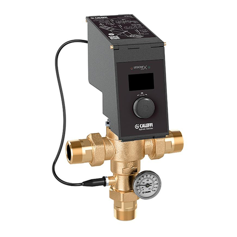
CALEFFI LEGIOMIX 6000 series Installation and commissioning manual
