Gavita Pro line EFM Series User manual

Pro line
1 Introduction
Thank you for purchasing the Gavita EFM. This manual describes the mounting and installing of the product and also describes
how to use the product. Please read and understand this manual completely before using the product. Only use the product as
specified in this manual.
1.1 Used symbols
Warning! A warning indicates severe damage to the user and/or product may occur when a procedure is not carried
out as described.
Caution! A caution sign indicates problems may occur if a procedure is not carried out as described. It may also serve
as a reminder to the user.
Note: A note gives additional information, e.g. for a procedure.
This symbol is an internationally recognized symbol used to designate recyclable materials.
This symbol is a certification mark employed on electronic products manufactured or sold in the United States which
certifies that the electromagnetic interference from the device is under limits approved by the Federal Communications
Commission.
This symbol shows that a product has been independently tested and certified to meet recognized standards for safety.
The symbol on the material, accessories or packaging indicates that this product may not be discarded as household
waste. By disposing of the equipment in the proper way, you will be helping to prevent possible risks to the environment
and public health, which might otherwise be caused by improper handling of the discarded equipment. Recycling of
materials contributes to the conservation of natural resources. Therefore, please do not dispose of your old electronics
and electrical appliances via household waste.
2 Product description
The Gavita EFM is an add-on product to the Gavita ELxF Master Controllers. When connected to the Master controller, the EFM
will switch an AC fan based on the output of the Master controller.
3 Product information and specifications
3.1 General product information
Product name EFM1 US 120 EFM1 US 240 EFM1 UK EFM1 EU
Manufacturer Gavita International bv
EAN Code 8718403055818 8718403055825 8718403055849 8718403055832
Part number 10103-6042116 10103-6042216 10103-6042212 10103-6042211
Plug type NEMA 5-15 NEMA 6-15 BS 1363 CEE 7
3.2 Technical specifications
Product weight 1kg / 2.2lbs
Dimensions (L*W*H) 155x88x70 mm / 6.1x3.5x2.8"
Temperature case < 70 °Celsius / 158 °Fahrenheit
Gavita EFM Accessory for Gavita Master Controller
Temperature ambient 0 ~ 35 °Celsius / 32 ~ 95 °Fahrenheit
Max voltage +/-10% 120V AC 240V AC 240V AC 230V AC
Max current 6A 6A 6A 6A
Max power 0.72kW 1.44kW 1,44kW 1,38kW
Min Power 20W 25W 25W 25W
Control port 0..10V 4P4C RJ9 connect to Gavita Fan port
Output range 10-100%
Max signal cable length <20m / 65ft
Relative humidity 25- 70% (not condensating)
Frequency 50 - 60 Hz
Certification FCC Class B up to 700W
Insulation Class 1 - requires an earth connection
IP rating IP 20
Fuse User accessible, replace with similar fuse only
3.3 Environment
The product is intended to be used in greenhouses and climate rooms. The product can be used in damp environments. The
product may not be used in wet environments or outdoors.
3.4 Legal
This device complies with Part 15 of the FCC Rules, designated as Class B.
For household use.
4 Safety recommendations and warnings
Warning! Carefully read the warnings below before using or working with the
product!
• Always adhere to the local rules and regulations when installing or using the
product.
• Do not use the product when either its signal cable or its power cord is damaged.
• Modifications to the cords can be dangerous and will void the warranty, it also
makes the product not comply with legal requirements.
• Do not expose the product to:
-condensing humidity, heavy mist, fog or direct spray;
-temperatures outside the specified range;
-dust and contamination.
• Always disconnect the product from mains before performing any task on it.
• The status LED blinks when it detects overtemperature in the housing.
• Don’t restrict airflow to the heatsink (1).
• Keep the cooling fins clean.
• Always use the same type of fuse. Using a different type will
void the warranty.
• The fan may sound differently due to the use of noise
cancelling technology.
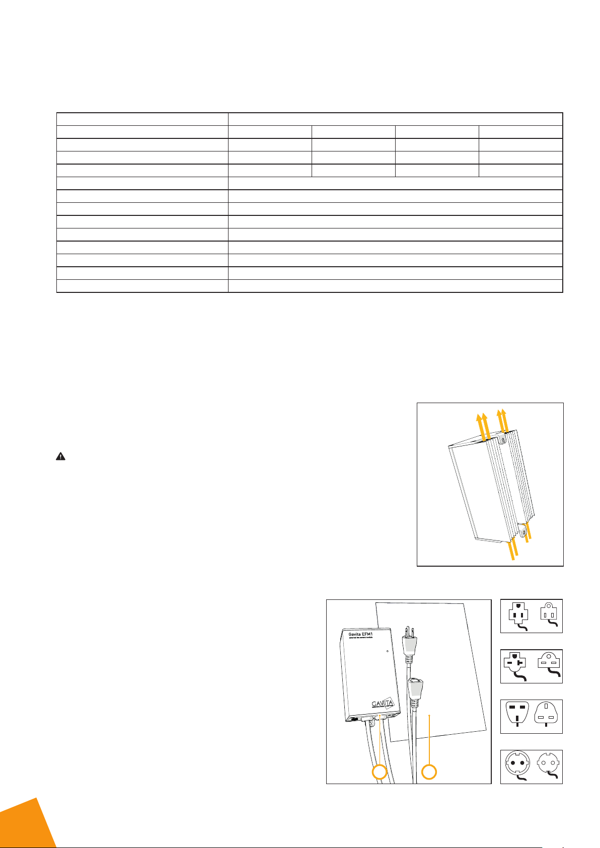
5 Contents (2)
A. EFM with local power plug
(plugs and contra plugs
displayed seperately)
B. Manual
1. Do not block airflow
UK plug 240 V
EU plug 240 V
US plug 120 V
US plug 240 V
AB
2. Contents

6 Controls, connections and indications (2)
A. Status LED
Off: product is not powered
On: product is powered
Blinking: overtemperature detected, power off*
* LED blinks during power up as well
B. Fan port RJ
7 Installing the EFM
Warning! Keep the EFM away from water, extreme temperatures, moisture, dust and
contamination.
Warning! Do not block the cooling fins on either side of the housing.
Caution! Mount the EFM within signal cable length of the Master controller or use a suitable
longer cable (<20 meters / <65 ft).
Note: Cable fasteners and screws are not included.
• Mount the EFM close to the wall outlet or ensure you have an extention cord present to
connect the EFM to the mains.
• Screw one screw in the wall. Use a screw anchor if necessary.
• Hang the EFM on the screw.
• Secure the EFM with a second screw.
8 Connecting the EFM to the Master controller
Warning! Never connect the EFM to any other device than the Gavita ELxF Master controller.
Warning! Never connect more than one EFM to each fan port of the Master controller.
• Connect the RJ cable to the fan output port of the ELxF.
• Connect the RJ cable to the fan input port of the EFM.
9 Connecting an AC fan
Warning! Ensure that the voltage and current requirements of the AC fan does not exceed the capacity of the EFM and the
local cabling! (see paragraph 3).
Caution! Gavita recommends you install and connect the EFM before plugging it into the mains.
Note: Power plugs are delivery dependent.
• Plug the power plug of the AC fan in the contra plug of the EFM (6A).
5. Connecting the EFM to the ELxF
A
B
3. Controls, connections and indications
4. Installation

GAVITA International bv
Oosteinderweg 127
1432 AH Aalsmeer
The Netherlands
Tel : +31(0)297-380 450
Fax : +31(0)297-380 451
W : www.gavita.com
Manual: Gavita EFM
Changes reserved - Version 18/45
• Plug the power plug of the EFM in the mains (6B).
9.1 Using an FB1 fan balancer
• Limit the airflow by using an FB1 Fan Balancer. This
is typically used in a two fan setup. Consult your ELxF
manual for more information.
10 Maintenance and repair
Warning! Disconnect the product from mains before performing any maintenance or repairs.
Warning! Do not open or disassemble the product, it contains no servicable parts inside. Opening the product can be
dangerous and will void the warranty.
• Regularly check the product for dust or dirt buildup. Clean if necessary. Contamination may couse overheating and
decreased performance.
• Clean the product only with a soft, dry cloth.
• Regularly check the wiring of the product to ensure it is undamaged.
11 Storage and disposal
• Store the product in a dry and clean environment, with an environmental temperature of -20 ~ 85 °Celsius /
-4 ~ 185 °Fahrenheit.
• The product must not be discarded as unsorted municipal waste, but must be collected separately for the purpose of
treatment, recovery and environmentally sound disposal.
12 Warranty
Gavita International bv warrants the mechanical and electronic components of their product to be free of defects in material
and workmanship if used under normal operating conditions for a period of three (3) years from the original date of purchase.
If the product shows any defects within this period and that defect is not due to user error or improper use Gavita International
bv shall, at its discretion, either replace or repair the product using suitable new or reconditioned products or parts. In case
Gavita International bv decides to replace the entire product, this limited warranty shall apply to the replacement product for
the remaining initial warranty period, i.e. three (3) years from the date of purchase of the original product. For service return
the fixture to your shop with the original sales receipt.
A
B
6. Connecting the EFM to fan and mains
Fan Balancer
EFM EFM
Exhaust
Intake
7. Using an FB1 fan balancer
This manual suits for next models
8
Table of contents
Popular Control Unit manuals by other brands


Keyautomation
Keyautomation CT102 Instructions and warnings for installation and use

fox&summit
fox&summit FS-CB100 quick start guide

TECH FASS
TECH FASS APS mini Plus MREM 65 Series user guide

Sun Power
Sun Power E Series Safety and installation instructions

d & b audiotechnik
d & b audiotechnik 10D quick start guide

AutomationDirect
AutomationDirect Productivity2000 P2-08ND3-1 manual