CSR Edmonds User manual

Product Manual

2
Item Checklist
1
2
3
Additional Parts & Tools Required (Not Supplied)
Hammer
Impact Drill & 6mm Masonry Drill Bit
Screwdriver with Phillips (P2) Bit
Marker Pen
Cable Ties
Included Parts: QTY:
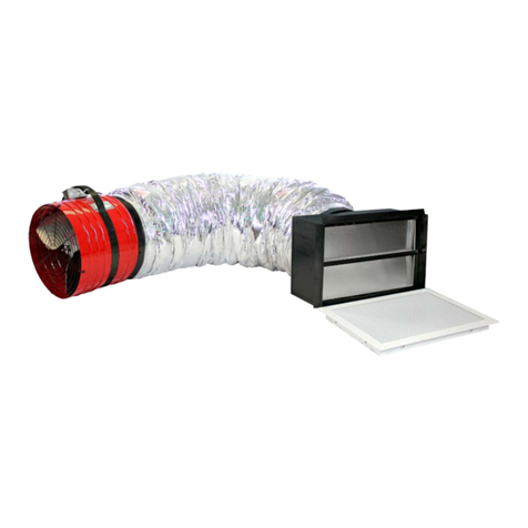
1 ecoFAN™ (1)
2 Speed Controller (1)
3 Power Supply (1)
5 6mm Wall Plugs (4)
6 8Gx32mm CSK Screws (4)
7 Product Manual (1)
8 Warranty Document (1)
4 Speed Controller Fixing
Screws 6Gx13mm (2)

3
Important Notes
The ecoFAN™ is designed for general household ventilation only. DO
NOT use to exhaust hazardous or explosive materials and vapours.
One side of the ecoFAN™ has an unguarded fan assembly. DO NOT
use in locations that expose the unguarded side to areas readily
accessible to people or animals.
Always use the provided power supply and speed controller to power
the fan. Failure to do so can damage the product.
Ensure that the power supply and speed controller are not left on
damp surfaces, fasten to available structure with cable ties if
required.
Only use one ecoFAN™ per speed controller and power supply.
Important Notices and Warnings
WARNING: Do not proceed with the installation until you have read the
entire instructions, including these warnings.
Install at your own risk
The installation of this product may be dangerous and includes the
potential of personal injury or property damage. Please take care when
installing this product and be mindful of risks. Please be aware of the
following when installing this product.
Installation requires the cutting and removal of bricks. This process
can produce airborne debris and other hazards. To minimise risks
wear personal protection equipment such as appropriate eye
protection, gloves and a dust mask.
When selecting a location for the ecoFAN™ make sure that the area
is clear of services such as pipes and power cables.

4
STEP 1
Select
appropriate
position. Using
the fan housing
as a guide,
mark out a
circle/location
on the wall.
Installation
STEP 2—Option A
Using an impact
drill and 6mm drill
bit. Drill holes
spaced 3-4 cm
around the
marked
perimeter.
Using a hammer
carefully knock
out the bricks to
form a circular
hole in the wall.

5
STEP 3
Clear the hole
of debris.
Installation
STEP 2—Option B
Remove the
complete top and
bottom shaded
bricks.
Cut and remove
the middle shaded
bricks.

6
Installation
STEP 5
Remove the unit
and using a 6mm
masonry bit, drill
mounting holes
as marked
previously.
STEP 4
Insert the
ecoFAN™ into the
hole. Make sure it
is level and the
correct way up.
Mark the
positions of the
mounting holes.
The back of the wall
grille has a mark to
indicate correct
orientation.

7
STEP 6
Insert supplied
wall plugs into the
6mm drilled
mounting holes.
Tap into hole with
hammer until
flush.
Installation
STEP 7
Using the supplied
screws, screw the
ecoFAN™ into the
wall plugs.

8
Installation—Electrical Connection
STEP 1
Connect the speed
controller long cable
to the ecoFAN™
cable.
STEP 2
Connect the Speed
controllers short
cable to the power
supply cable.
STEP 3
Connect the power
supply to a mains
socket. Turn on and
check ran funs
freely.
STEP 4
Using either the
screws supplied or
cable ties mount the
speed controller and
the power supply in
a suitable location
that prevents them
from getting wet.
STEP 5
Set the control mode.
Ensure the power supply and speed controller
are not in contact with damp or wet surfaces.

9
Installation—Speed Control Mode
The speed controller has 4 operating modes. These are selectable
via the 4 position selector on the controller box.
To adjust use a 2mm flat screwdriver to turn the switch to the
desired position. This can be done whilst the product is running.
The default starting position is LO.
MODES:
LO (Default) - Continuous operation, low speed, low flow rate,
very quiet, very low power consumption.
MED - Continuous operation, moderate speed, moderate flow
rate.
HI - Continuous operation, high speed, high flow rate.
AUTO - This setting is not suitable for the ecoFAN™ when used
as a sub-floor ventilator
If in Auto mode the ecoFAN™ will automatically adjust the fan speed
dependent on temperature. It will turn off below 30°C. The fan speed
will gradually ramp up through to maximum speed at 45°C.

10
Convert From Exhaust to Supply Flow Direction
STEP 1
Remove the 4
screws fixing the
fan housing to the
wall grille.
There are arrows on the motor housing that indicate the direction
of airflow
STEP 2
Reverse the fan
housing and using
the same screws
mount the housing
to the wall grille.
The motor cable should always be pointing downwards.

11
Removing Wall grille for Painting
STEP 1
Remove the 4
screws fixing the
fan housing to the
wall grille.
STEP 2
Paint wall grille and
allow to dry.
Reattach the wall
grille to the fan
housing using the
screws removed
earlier (Step 1 in
reverse).
The plastic used for the wall grille is suitable for painting with
standard spray paints without priming. The surface must be clean
before painting.

12
Technical Data
Material:
Wall Grille: Plastic (ASA)
Fan & Motor Housing: Plastic (PP-TD20)
Fan Impeller: Plastic (PA6-GF30)
Screws: Stainless Steel (304)
Weight: 1.5 kg
Electrical:
Power Supply
Type: ElectronicSwitchingMode
Input: 100-240VAC, 1~, 50/60Hz, 2A
Output: 24 VDC
Fan Motor: Electronic Commutating (EC) motor
Internal Voltage: 24 VDC
Protection Class: IP54
Speed Control
Type: Temperature Sensing Electronic
Variable Speed Controller
Input Voltage: 24 VDC
Fixed Speed Operation: Three fixed speeds (LO, MED & HI),
manually selectable via rotary selector
switch.
AutomacVariable
SpeedOperaon:
Variable speed response relative to
ambient temperature of speed
controller location.
- Off below 30°C
- LO at 30°C
- Gradual ramp up to HI at 45°C

13
Performance Data & Product Dimensions
Speed
Sound Pressure
Level (SPL) LA
@ psF=0
[dB(A)]
Max. running power
consumption [W]
Flow rate qv@ psF=0
[m3/hr]
LO32.84.4280
MED4311.6457
HI53.530734
NOTE—Sound pressure level measured 1m from fan inlet

14
FAQ & Troubleshooting
Troubleshooting
Problem Possible Actions
Motor / Fan Not Running
Controller may be in AUTO Mode (It will not run at
a temperature less than 30°C when in AUTO)
Change to LO to confirm controller is functioning
correctly
Check all connections are secure
Check Power supply is plugged in
Check Power Socket is turned on
Q: Do I need an electrician to install the ecoFAN™?
A: If you have an available power point that can be reached then no
electrician is required. If a power point is unavailable then an
electrician will be required to install one.
Q: Can I wire it directly into the mains power?
A: No, you must use the supplied power supply and speed controller for the
ecoFAN™ to work correctly. Failure to do so may damage the product.
Q: Can I duct the ecoFAN™?
A: Yes the ecoFAN™ can be ducted in either exhaust or inlet mode by
slipping 250mm diameter ducting over the lip of the motor housing and
fixing with tape.
Q: Can I paint the ecoFAN™?
A: Yes, standard spray paint can be used to paint the ecoFAN™. No plastic
primer is required, however the surface must be clean before paint
application. Do not get any paint on the motor/fan module. The product
should be disassembled to facilitate easier painting. Instructions on
disassembly can be seen on page 11 of this manual.

15
Edmonds | business division of CSR Building Products Limited ABN 55 008 631 356
10 Stanton Road, Seven Hills NSW 2147 Australia | www.edmonds.com.au
Contact Details
General Enquiries and Support
PH: 1300 858 674
Technical Ventilation Enquiries
PH: +61 2 8824 0444

Other CSR Fan manuals
