CSR Bradford EcoPower 400 User manual

Industrial Ventilators Installation
Instructions
EcoPower®and Hurricane®
Non-Cyclonic
PRINT IN COLOUR
V3.0 | 08/22
2
The contents of this install guide are copyright protected and may not be reproduced in any form without prior written consent of CSR. Recommendations and
advice regarding the use of the products described in this guide are to be taken as a guide only, and are given without liability on the part of the company or
its employees. We reserve the right to change product specifications without prior notification, please refer to the CSR website for the latest version of this
document. The purchaser should independently determine the suitability of the product for the intended use and application.
SYSTEM PRE-REQUISITES – Check Before Commencing
Before attempting to start the installation, please ensure that the following allowable roof pitch and
make-up air requirements can be met.
Product Make-up air* per ventilator - 100%
open, evenly distributed open area
Allowable Roof Pitch
EcoPower 400
Hurricane 100 - 400
≥0.3m² up to 45°
EcoPower 600
Hurricane 450 - 600
≥ 0.5m² up to 45°
EcoPower 900
Hurricane 700 - 900
≥ 0.9m² up to 22.5°
* Performance values are based on a 5Pa pressure loss across the make-up air opening.
Additional make-up air can be provided as per the recommendations in AS1668.2.
DO NOT PROCEED TO INSTALL THIS PRODUCT IF THE ABOVE REQUIREMENTS ARE NOT
MET
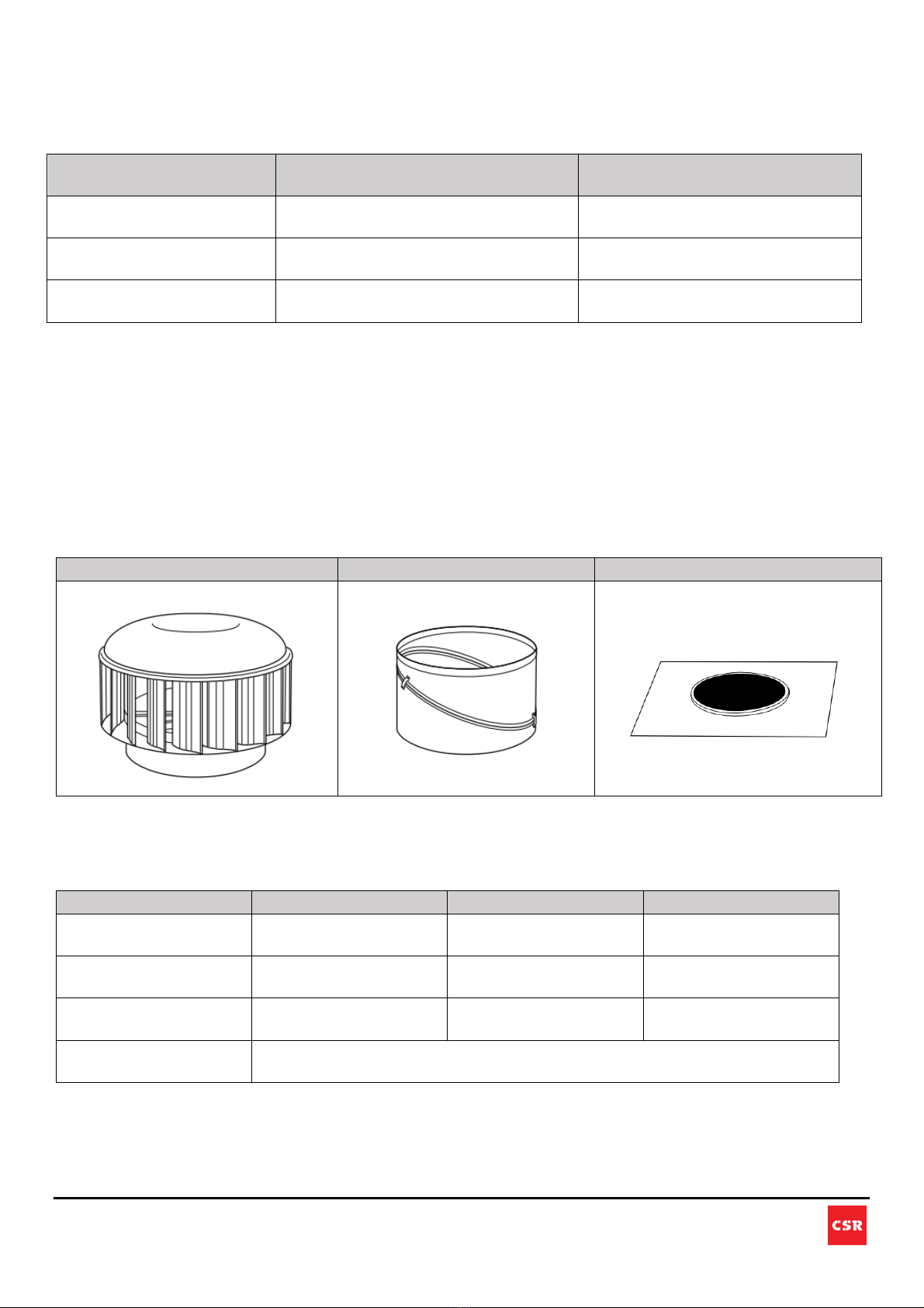
1. PACKING LIST (for a standard complete product) – Check Before Commencing
Included Parts
Additional Materials Required - Not Supplied
a. FASTENERS (Quantity and Type)
Product
Head to Varipitch
Varipitch to Flashing
Flashing to Roof
EcoPower 400
Hurricane 100 - 400
6 6 12
EcoPower 600
Hurricane 450 - 600
9 9 16
EcoPower 900
Hurricane 700 - 900
12 12 26
Fasteners
Use 10G X 16MM Galvanised Self Drilling TEK Screws with Neoprene
Washer or 5/32" (4.0mm) Rivets Aluminium/Steel Sealed
Ventilator Head
Varipitch
Flashing

3
The contents of this install guide are copyright protected and may not be reproduced in any form without prior written consent of CSR. Recommendations and
advice regarding the use of the products described in this guide are to be taken as a guide only, and are given without liability on the part of the company or
its employees. We reserve the right to change product specifications without prior notification, please refer to the CSR website for the latest version of this
document. The purchaser should independently determine the suitability of the product for the intended use and application.
b. SUPPLEMENTARY FLASHING required for installation away from the ridge – refer to section 4
for details.
c. PESTGUARD (if required) to provide protection against the entry of vermin.
IMPORTANT: Note regarding lifting this product
Lift the product in its original packaging using a crane or similar equipment to the roof mounting location,
prior to handling the product.
Caution During Lifting:
The ventilator top surface/dome can be easily scratched or deformed when placed upside down so always
place it on a soft/smooth surface such as cardboard or a soft-foam mat.

4
The contents of this install guide are copyright protected and may not be reproduced in any form without prior written consent of CSR. Recommendations and
advice regarding the use of the products described in this guide are to be taken as a guide only, and are given without liability on the part of the company or
its employees. We reserve the right to change product specifications without prior notification, please refer to the CSR website for the latest version of this
document. The purchaser should independently determine the suitability of the product for the intended use and application.
SAFETY AND WARNINGS
a. The installation of this product involves working at heights on a sloping surface and may be dangerous,
including the potential of death, personal injury, or property damage.
b. Follow the state or territory regulator OH&S guidelines for working at heights, electrical, working in
elevated temperatures (e.g. roof space in summer). For more information on your State OH&S
guidelines for working at heights, please refer to: https://www.safeworkaustralia.gov.au/heights
c. All ventilation products must be installed by a qualified installer and all electrical wiring (where
applicable) must be undertaken by a qualified electrician.
d. EcoPower Hybrid Ventilators use 220V-240V AC power for the electrically powered components and
electrical connections must only be undertaken by a qualified electrician.
e. EcoPower Hybrid Ventilators are supplied with either a Smart Controller or Interface Box - these devices
must not be tampered with and the hybrid ventilator must not be operated without either of these
devices.
f. Do not attempt to power up EcoPower Hybrid Ventilators when the product is not suitably roof mounted
as the turbine will rotate without warning and may create a hazard.
g. Due to the size and weight of the turbine, it is recommended that it is always lifted by 2 people or a
crane. Refer to the lifting instructions.
h. Damaged parts must be replaced with a genuine replacement part from CSR Bradford Ventilation.
i. The turbine head of this product can rotate without warning (even during installation) – always keep
body parts away from moving components.
j. Please read this manual carefully before installing this product and keep it for future reference or
provide it to the building owner/maintenance manager.
LIMITATIONS
Not suitable for use in cyclonic regions.
5
The contents of this install guide are copyright protected and may not be reproduced in any form without prior written consent of CSR. Recommendations and
advice regarding the use of the products described in this guide are to be taken as a guide only, and are given without liability on the part of the company or
its employees. We reserve the right to change product specifications without prior notification, please refer to the CSR website for the latest version of this
document. The purchaser should independently determine the suitability of the product for the intended use and application.
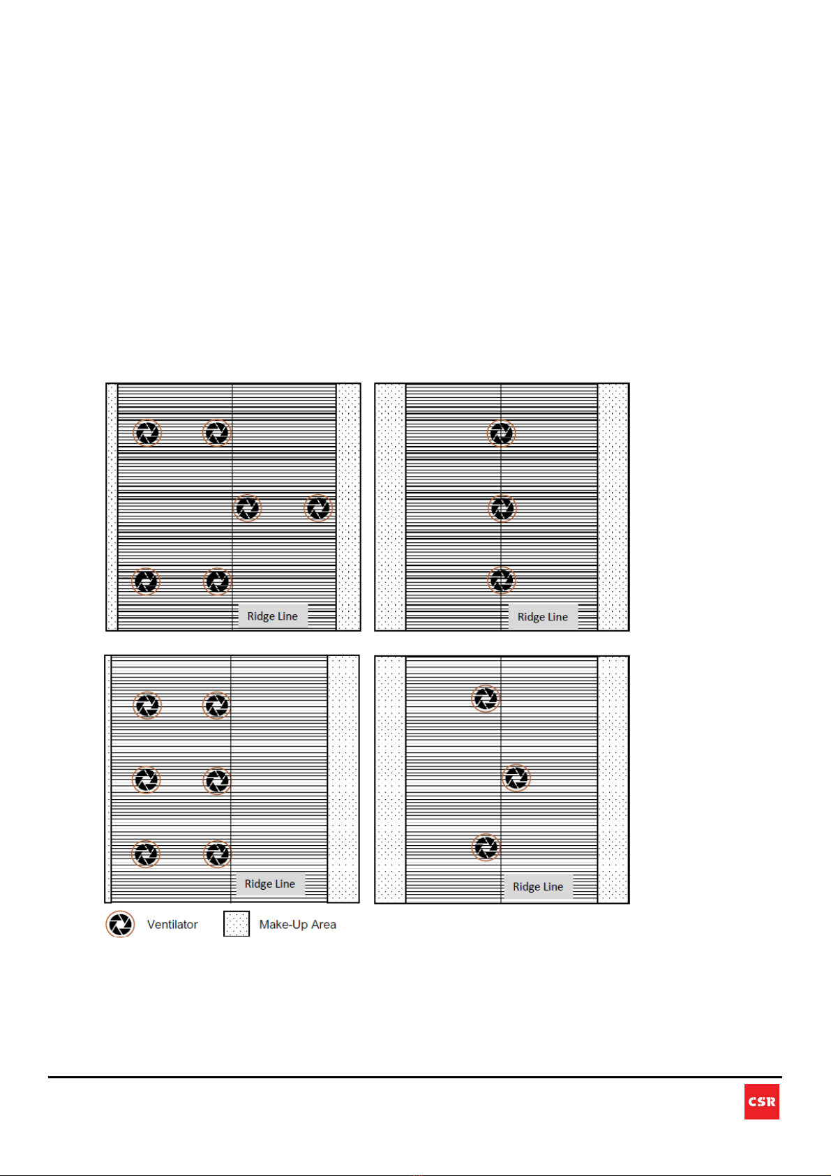
2. VENTILATOR POSITIONING & PROVISION FOR MAKE-UP AIR
CSR Bradford Ventilation recommends that ventilators are positioned 4m to 6m away from each other in all
directions for effective and efficient performance. It is also recommended that ventilators of the same size
are used together to prevent replacement air from being drawn between ventilators of different sizes.
Ensure that the ventilators are not sheltered from the wind by surrounding objects, the shadow angle
created by the roof ridge or by each other.
Make-up air is required for this ventilator to replenish the exhausted air. As a general guide, the largest
make-up air entry should be positioned on the opposite side of the building to the largest ventilator demand.
The make-up air location should be positioned at optimum height to provide efficient sweeping of the floor
area.
The illustrations below provide a number of generic ventilator and make-up air layouts but it should be
noted that a whole-of-building assessment, as per AS1668.2, should be conducted by a suitably qualified
person prior to deciding upon site-specific ventilator and make-up air placement.
IMPORTANT: If external make-up air is insufficient, the ventilators will draw make-up air from each other –
this will both diminish the effectiveness of the system and increase the risk of the system drawing external
water into the building during periods of rain. It is also recommended that ventilators of the same size are
used together to prevent replacement air from being drawn between ventilators of different sizes.

6
The contents of this install guide are copyright protected and may not be reproduced in any form without prior written consent of CSR. Recommendations and
advice regarding the use of the products described in this guide are to be taken as a guide only, and are given without liability on the part of the company or
its employees. We reserve the right to change product specifications without prior notification, please refer to the CSR website for the latest version of this
document. The purchaser should independently determine the suitability of the product for the intended use and application.
3. INSTALLATION UNDER THE RIDGE
Note: See Section 4 for installation away from the ridge.
a. Set Position: Place the base flashing under the ridge cap at the required position and adjust the
position to avoid structural roof members below the roof sheet. Ensure the flashing covers the
corrugation or ribs equally on each side of the flashing, then mark a circle on the roof using the hole in
the flashing as a template.
7
The contents of this install guide are copyright protected and may not be reproduced in any form without prior written consent of CSR. Recommendations and
advice regarding the use of the products described in this guide are to be taken as a guide only, and are given without liability on the part of the company or
its employees. We reserve the right to change product specifications without prior notification, please refer to the CSR website for the latest version of this
document. The purchaser should independently determine the suitability of the product for the intended use and application.
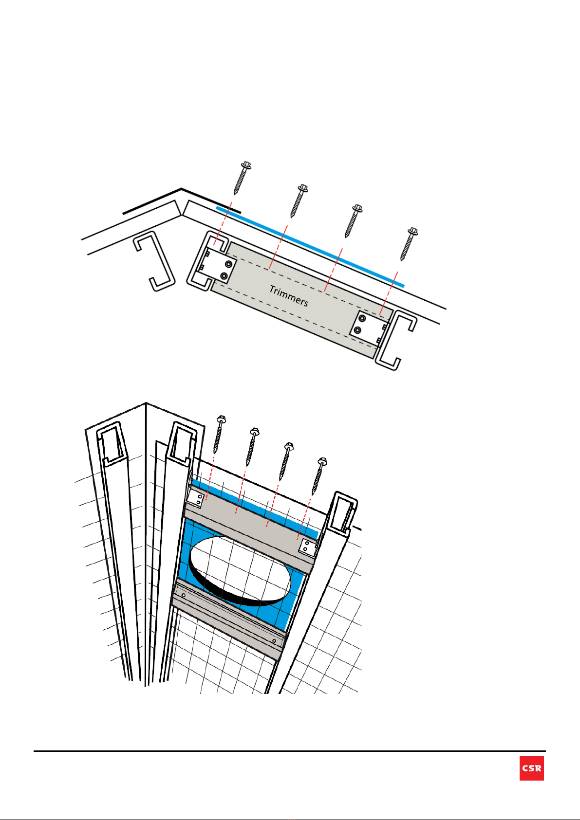
Important Note Regarding Roof Structural Support:
EP400 - EP600 & H100 – H600 – If the purlin spacing is larger than 600mm, trimmers are
required. Install the trimmers between the purlin on either side of the opening. Do not cover the
openings.
EP900 & H700 – H900 – If the purlin spacing is larger than 1000mm, trimmers are required.
Install the trimmers between the purlin on either side of the opening. Do not cover the opening.
Purlin
Flashing
8
The contents of this install guide are copyright protected and may not be reproduced in any form without prior written consent of CSR. Recommendations and
advice regarding the use of the products described in this guide are to be taken as a guide only, and are given without liability on the part of the company or
its employees. We reserve the right to change product specifications without prior notification, please refer to the CSR website for the latest version of this
document. The purchaser should independently determine the suitability of the product for the intended use and application.
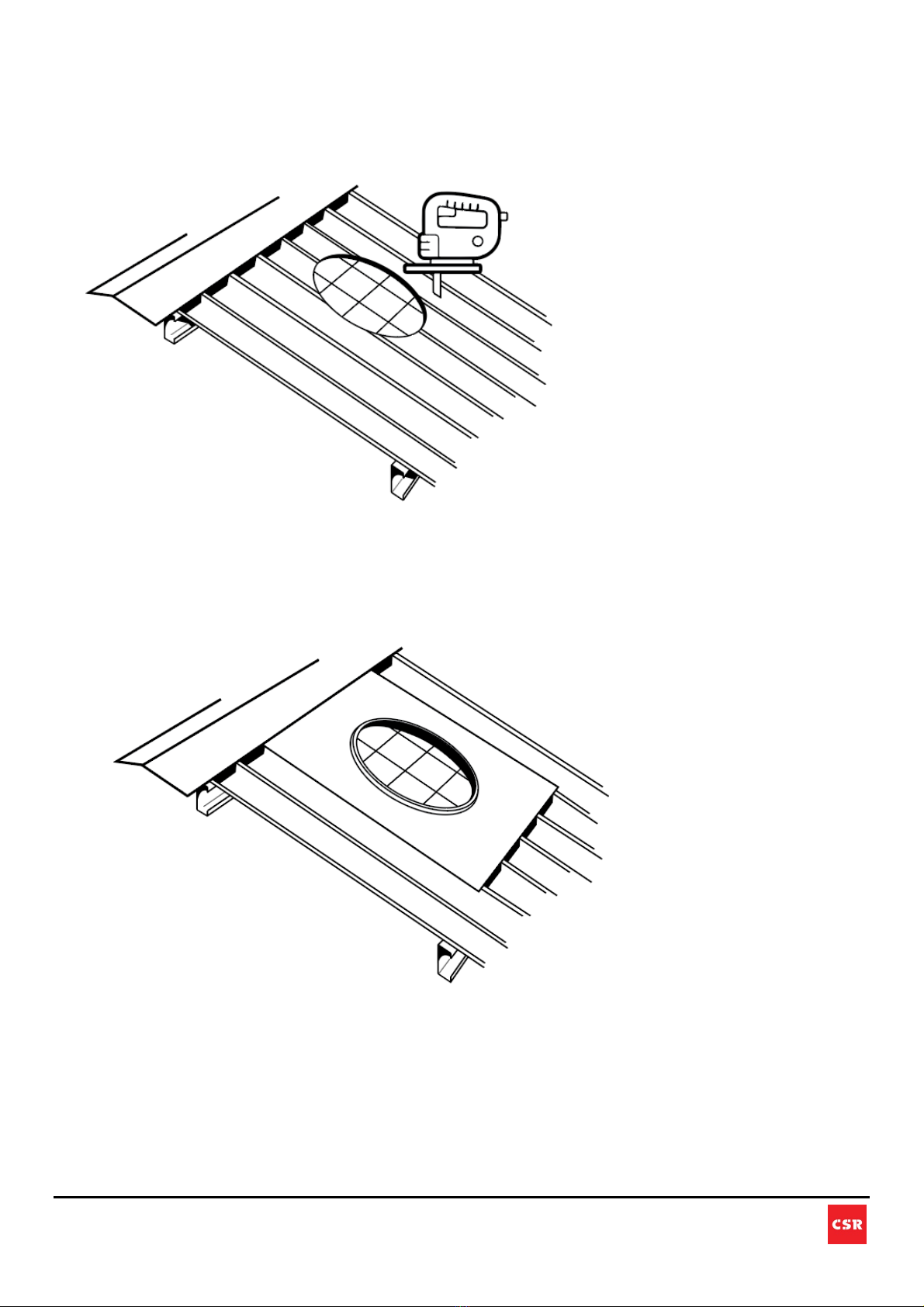
b. Cut Hole: Carefully cut the hole, remembering that there may be insulation and other roof
members under the roof sheet. Once the hole has been cut, fold up the edge of the
corrugations or pans. Ensure the roofing safety mesh/net integrity is maintained after the
installation.
c. Secure Flashing: Attach the flashing under the ridge cap and apply sealant prior to final fixing
(refer to the table below for the required number of fasteners). If trimmers are used ensure the
flashing is secured to the trimmers. Seal all fasteners with a suitable sealant to ensure they are
weatherproof.

9
The contents of this install guide are copyright protected and may not be reproduced in any form without prior written consent of CSR. Recommendations and
advice regarding the use of the products described in this guide are to be taken as a guide only, and are given without liability on the part of the company or
its employees. We reserve the right to change product specifications without prior notification, please refer to the CSR website for the latest version of this
document. The purchaser should independently determine the suitability of the product for the intended use and application.
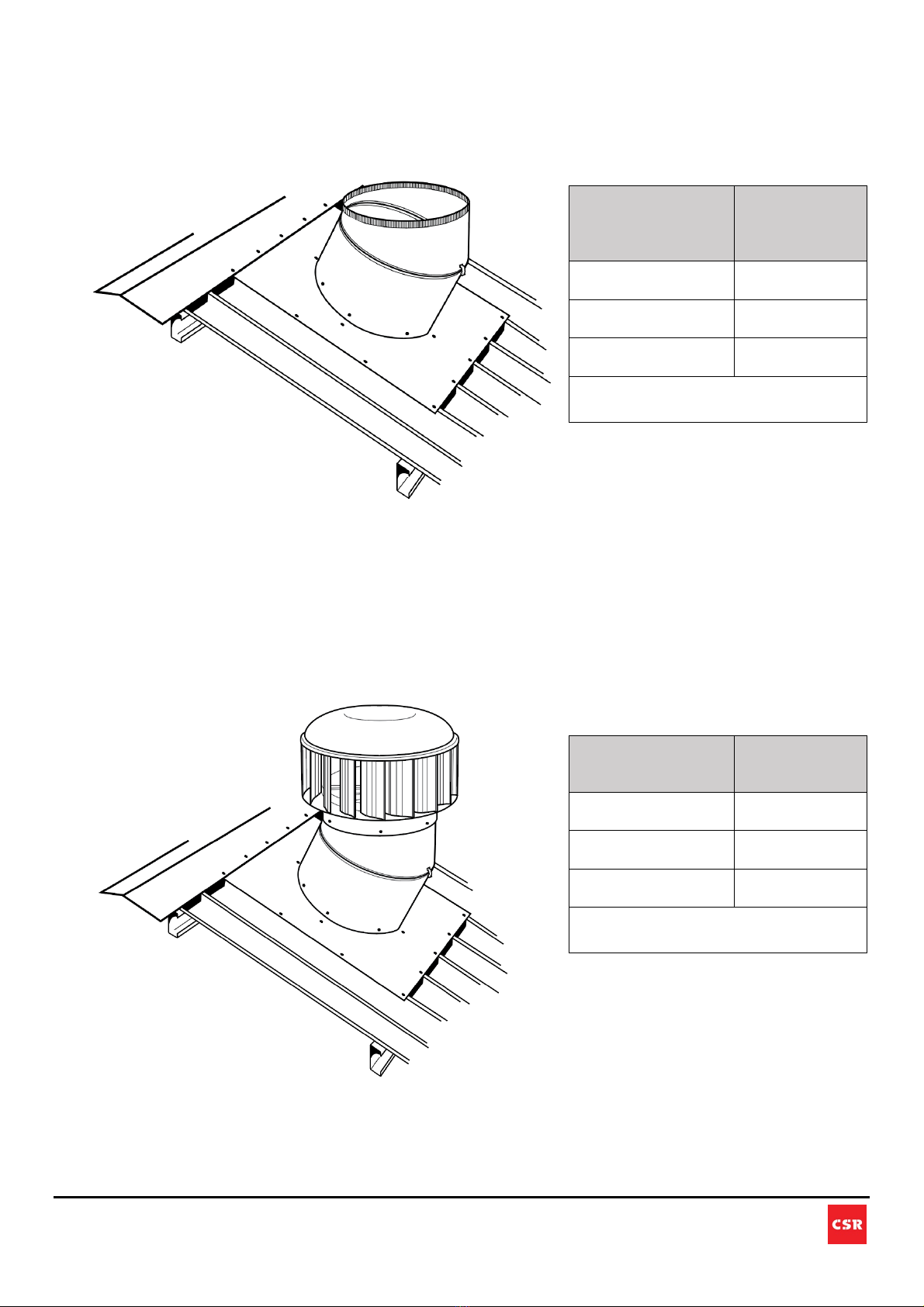
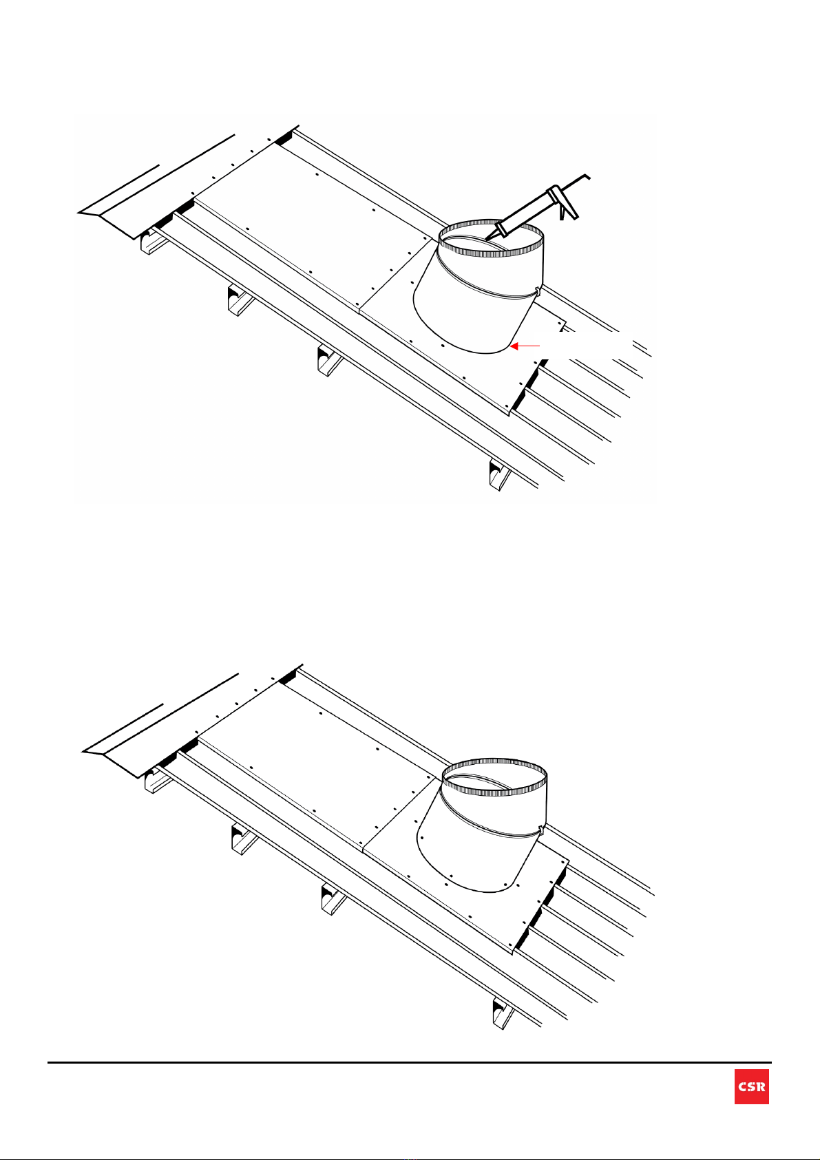
d. Assemble the Varipitch: When a Varipitch throat is being used, position the Varipitch on the
flashing and rotate the top and bottom halves until the top of the Varipitch is level (horizontal) -
it is recommended that an electronic or spirit level is used to ensure that the top edge of the
throat is horizontal in all directions.
Model
Fasteners to
secure flashing
to roof
EcoPower 400
Hurricane 100 -
400
12 (4 near throat)
EcoPower 600
Hurricane 450 -
600
18 (4 near throat)
EcoPower 900
Hurricane 700 -
900
26 (4 near throat)
Use 10G X 16MM Galvanised Self Drilling TEK
Screws with Neoprene Washer or 5/32"
(4.0mm) Rivets Aluminium/Steel Sealed
10
The contents of this install guide are copyright protected and may not be reproduced in any form without prior written consent of CSR. Recommendations and
advice regarding the use of the products described in this guide are to be taken as a guide only, and are given without liability on the part of the company or
its employees. We reserve the right to change product specifications without prior notification, please refer to the CSR website for the latest version of this
document. The purchaser should independently determine the suitability of the product for the intended use and application.
e. Secure the Varipitch Angle: With the Varipitch upper throat positioned horizontally, lock it into
position using the supplied Varipitch clip. Use either self-tapping screws or blind rivets to
secure all the clips between the two halves of the Varipitch.
f. Weather Sealing: Seal the Varipitch seam on the inside with a bead of weather-resistant
suitable sealant.
NOTE: DO NOT apply sealant to the joint between the flashing and Varipitch. This is a natural
gutter to release any trapped condensation. See details in section (i) below.
Do Not Seal
11
The contents of this install guide are copyright protected and may not be reproduced in any form without prior written consent of CSR. Recommendations and
advice regarding the use of the products described in this guide are to be taken as a guide only, and are given without liability on the part of the company or
its employees. We reserve the right to change product specifications without prior notification, please refer to the CSR website for the latest version of this
document. The purchaser should independently determine the suitability of the product for the intended use and application.
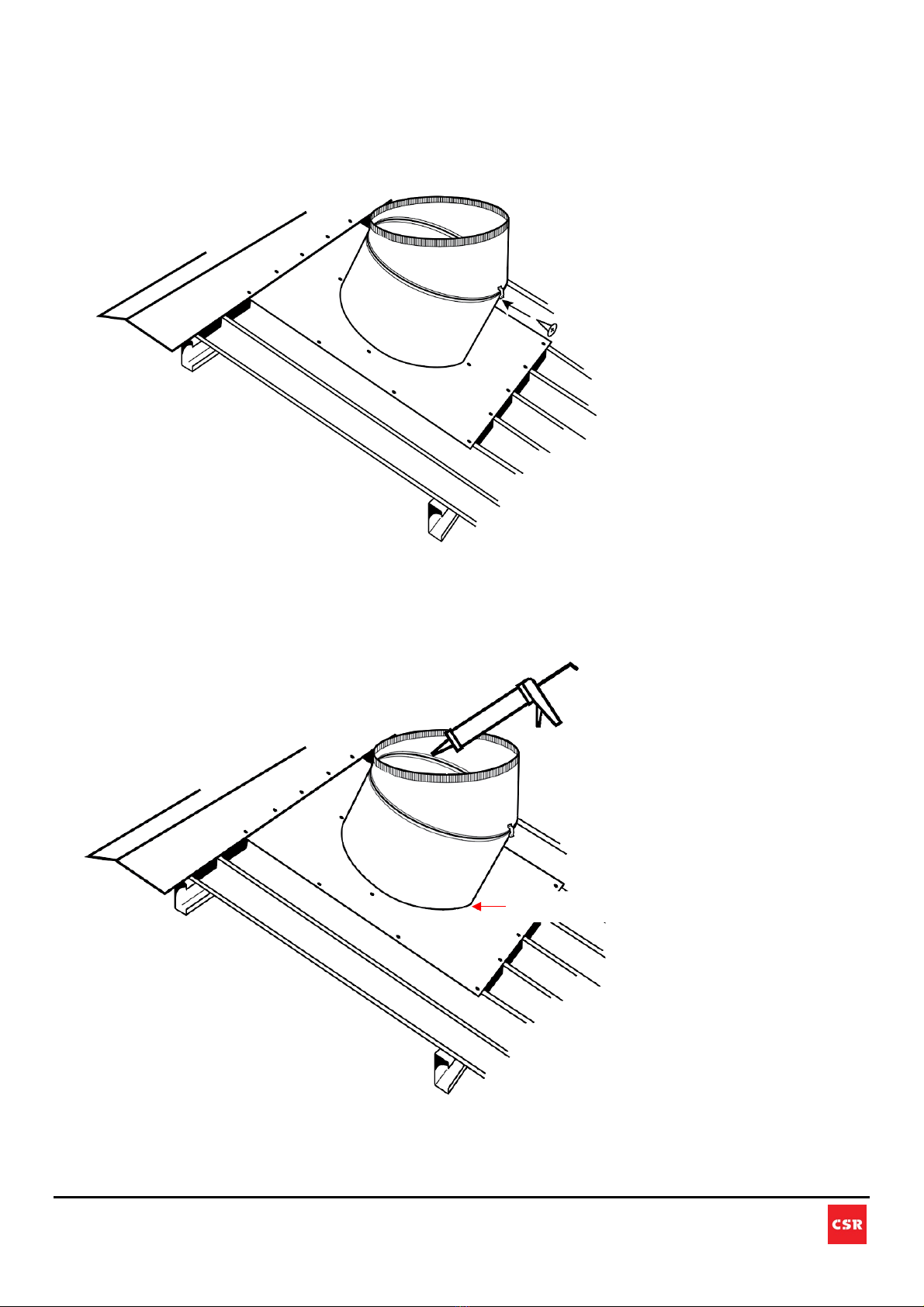
g. Secure Varipitch to Flashing: Reposition the Varipitch on the Flashing and check it is
horizontal - secure the Varipitch to the flashing using the recommended number of screws
shown in the table below – DO NOT SEAL this connection.
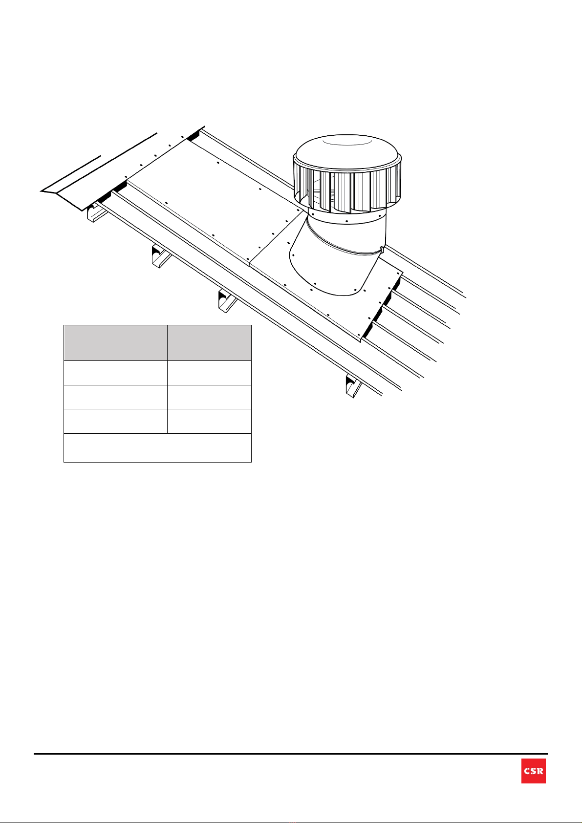
h. Assemble Turbine: Assemble the turbine head to the Varipitch. Re-check if the assembly is
level (horizontal) and adjust the turbine by tilting the throat slightly if required. Ensure the
knurling (the tapered section of the Varipitch) is fully inside the ventilator throat and secure the
ventilator throat by fastening it to the top of the Varipitch with the number of fasteners shown in
the table below.
NOTE: DO NOT apply sealant to the joint between the turbine and Varipitch. This is a natural
gutter to release any trapped condensation. See details in section (i) below.
Model
Fasteners to
secure
varipitch to
flashing
EcoPower 400
Hurricane 100 - 400
6
EcoPower 600
Hurricane 450 - 600
9
EcoPower 900
Hurricane 700 - 900
12
Use 10G X 16MM Galvanised Self Drilling TEK
Screws with Neoprene Washer or 5/32" (4.0mm)
Rivets Aluminium/Steel Sealed
Model
Fasteners to
secure turbine
to varipitch
EcoPower 400
Hurricane 100 - 400
6
EcoPower 600
Hurricane 450 - 600
9
EcoPower 900
Hurricane 700 - 900
12
Use 10G X 16MM Galvanised Self Drilling TEK
Screws with Neoprene Washer or 5/32" (4.0mm)
Rivets Aluminium/Steel Sealed

12
The contents of this install guide are copyright protected and may not be reproduced in any form without prior written consent of CSR. Recommendations and
advice regarding the use of the products described in this guide are to be taken as a guide only, and are given without liability on the part of the company or
its employees. We reserve the right to change product specifications without prior notification, please refer to the CSR website for the latest version of this
document. The purchaser should independently determine the suitability of the product for the intended use and application.
i. Sealing is crucial for this product to ensure no leaking occurs during its lifespan, but there is
also a requirement for drainage. To ensure that only the required areas are sealed and the
drainage path is left open, follow this guide carefully:
Location Area Sealing Requirement
All fasteners Seal
Flashing perimeter to roof Seal
Varipitch seam (inside throat) Seal
Turbine to varipitch Do Not Seal
Varipitch to flashing Do Not Seal
Flashing bottom edge to roof Do Not Seal
Do Not Seal
Do Not
Seal
Do Not Seal

13
The contents of this install guide are copyright protected and may not be reproduced in any form without prior written consent of CSR. Recommendations and
advice regarding the use of the products described in this guide are to be taken as a guide only, and are given without liability on the part of the company or
its employees. We reserve the right to change product specifications without prior notification, please refer to the CSR website for the latest version of this
document. The purchaser should independently determine the suitability of the product for the intended use and application.
4. INSTALLATION AWAY FROM RIDGE
a. Set Position: Place the base flashing at the required position and adjust the position to avoid structural
roof members below the roof sheet. Ensure the flashing covers the corrugation or ribs equally on each
side of the flashing, then mark a circle on the roof using the hole in the flashing as a template.

14
The contents of this install guide are copyright protected and may not be reproduced in any form without prior written consent of CSR. Recommendations and
advice regarding the use of the products described in this guide are to be taken as a guide only, and are given without liability on the part of the company or
its employees. We reserve the right to change product specifications without prior notification, please refer to the CSR website for the latest version of this
document. The purchaser should independently determine the suitability of the product for the intended use and application.
Important Note Regarding Roof Structural Support:
EP400 - EP600 & H100 – H600 – If the purlin spacing is larger than 600mm, trimmers are
required. Install the trimmers between the purlin on either side of the opening. Do not cover the
openings.
EP900 & H700 – H900 – If the purlin spacing is larger than 1000mm, trimmers are required.
Install the trimmers between the purlin on either side of the opening. Do not cover the opening.
Purlin
Flashing
15
The contents of this install guide are copyright protected and may not be reproduced in any form without prior written consent of CSR. Recommendations and
advice regarding the use of the products described in this guide are to be taken as a guide only, and are given without liability on the part of the company or
its employees. We reserve the right to change product specifications without prior notification, please refer to the CSR website for the latest version of this
document. The purchaser should independently determine the suitability of the product for the intended use and application.
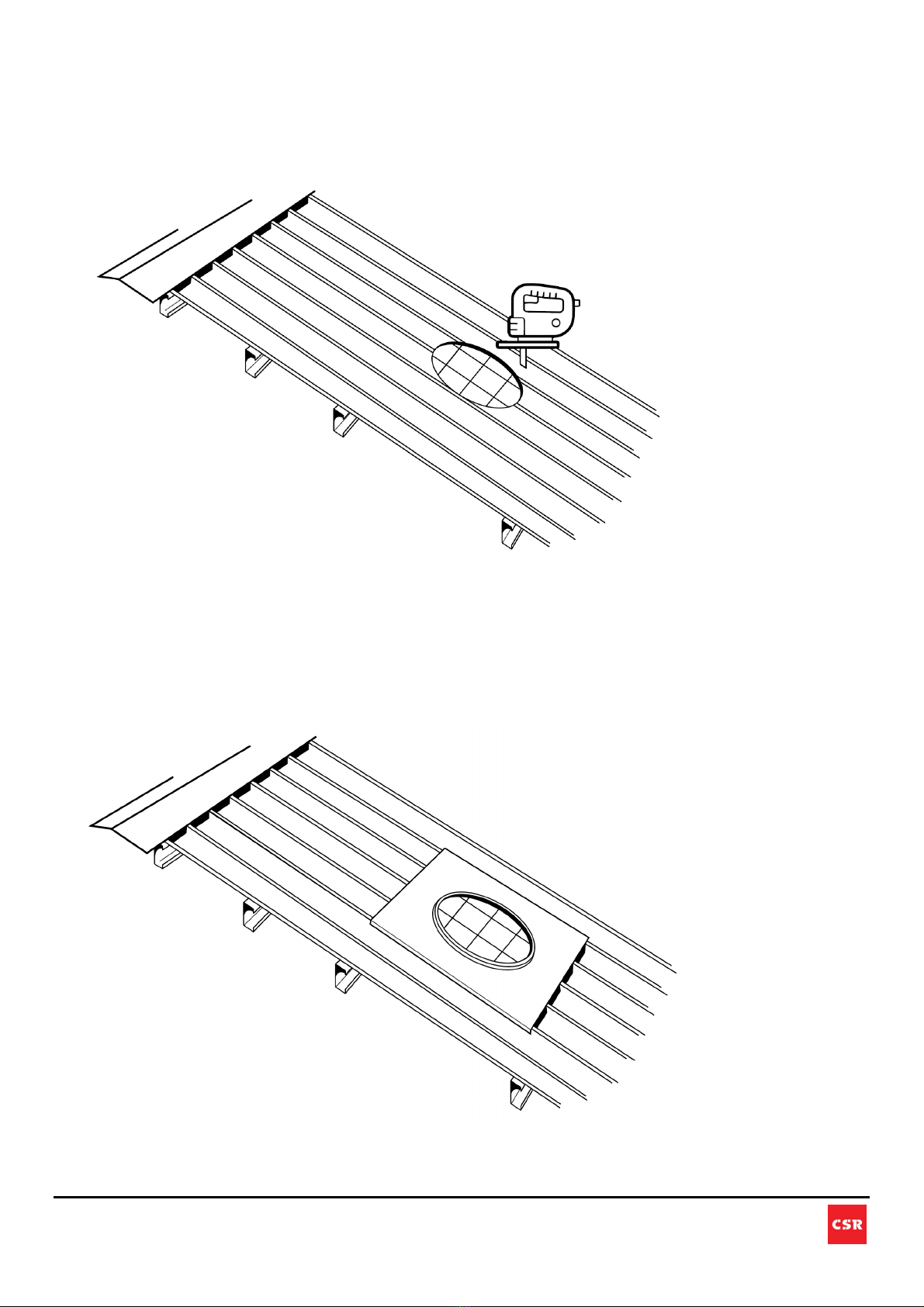
b. Cut Hole: Carefully cut the hole, remembering that there may be insulation and other roof
members under the roof sheet. Once the hole has been cut, fold up the edge of the
corrugations or pans. Ensure the roofing safety mesh/net integrity is maintained after the
installation.
c. Secure Flashing: Attach the flashing over the roof hole and back flashing tray to extend the
ridge to the ventilator’s flashing. Apply sealant prior to final fixing (refer to the table below for
the required number of fasteners). If trimmers are used ensure the flashing is secured to the
trimmers. Seal all fasteners with a suitable sealant to ensure they are weatherproof.

16
The contents of this install guide are copyright protected and may not be reproduced in any form without prior written consent of CSR. Recommendations and
advice regarding the use of the products described in this guide are to be taken as a guide only, and are given without liability on the part of the company or
its employees. We reserve the right to change product specifications without prior notification, please refer to the CSR website for the latest version of this
document. The purchaser should independently determine the suitability of the product for the intended use and application.
Model
Fasteners to
secure turbine
flashing to roof
EcoPower 400
Hurricane 100
- 400
12 (4 near throat)
EcoPower 600
Hurricane 450
- 600
18 (4 near throat)
EcoPower 900
Hurricane 700
- 900
26 (4 near throat)
Use 10G X 16MM Galvanised Self Drilling
TEK Screws with Neoprene Washer or
5/32" (4.0mm) Rivets Aluminium/Steel
Sealed
Extended Flashing
(not supplied)
Overlap requirement between extended
flashing and turbine flashing is 100mm to
250mm.
17
The contents of this install guide are copyright protected and may not be reproduced in any form without prior written consent of CSR. Recommendations and
advice regarding the use of the products described in this guide are to be taken as a guide only, and are given without liability on the part of the company or
its employees. We reserve the right to change product specifications without prior notification, please refer to the CSR website for the latest version of this
document. The purchaser should independently determine the suitability of the product for the intended use and application.
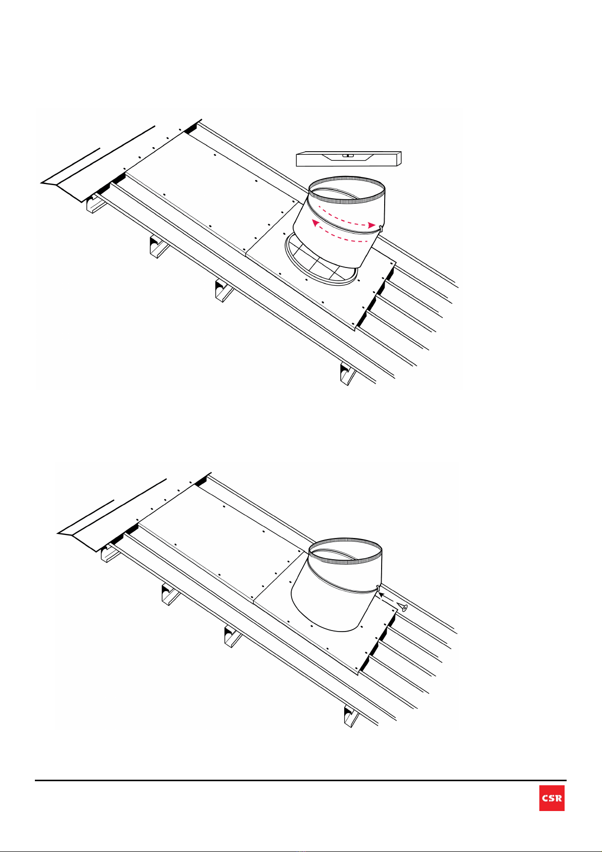
d. Assemble the Varipitch: When a Varipitch throat is being used, position the Varipitch on the
flashing and rotate the top and bottom halves until the top of the Varipitch is level (horizontal) -
it is recommended that an electronic or spirit level is used to ensure that the top edge of the
throat is horizontal in all directions.
e. Secure the Varipitch Angle: With the Varipitch upper throat positioned horizontally, lock it into
position using the supplied Varipitch clip. Use either self-tapping screws or blind rivets to
secure all the clips between the two halves of the Varipitch.
18
The contents of this install guide are copyright protected and may not be reproduced in any form without prior written consent of CSR. Recommendations and
advice regarding the use of the products described in this guide are to be taken as a guide only, and are given without liability on the part of the company or
its employees. We reserve the right to change product specifications without prior notification, please refer to the CSR website for the latest version of this
document. The purchaser should independently determine the suitability of the product for the intended use and application.
f. Weather Sealing: Seal the Varipitch seam on the inside with a bead of weather-resistant
suitable sealant.
NOTE: DO NOT apply sealant to the joint between the flashing and Varipitch. This is a natural
gutter to release any trapped condensation. See details in section (i) below.
g. Secure Varipitch to Flashing: Reposition the Varipitch on the Flashing and check it is
horizontal - secure the Varipitch to the flashing using the recommended number of screws
shown in the table below – DO NOT SEAL this connection.
Do Not Seal
19
The contents of this install guide are copyright protected and may not be reproduced in any form without prior written consent of CSR. Recommendations and
advice regarding the use of the products described in this guide are to be taken as a guide only, and are given without liability on the part of the company or
its employees. We reserve the right to change product specifications without prior notification, please refer to the CSR website for the latest version of this
document. The purchaser should independently determine the suitability of the product for the intended use and application.
h. Assemble Turbine: Assemble the turbine head to the Varipitch. Re-check if the assembly is
level (horizontal) and adjust the turbine by tilting the throat slightly if required. Ensure the
knurling (the tapered section of the Varipitch) is fully inside the ventilator throat and secure the
ventilator throat by fastening it to the top of the Varipitch with the number of fasteners shown in
the table below.
NOTE: DO NOT apply sealant to the joint between the turbine and Varipitch. This is a natural
gutter to release any trapped condensation. See details in section (i) below.
Model Fasteners to
secure turbine
to varipitch
EcoPower 400
Hurricane 100 - 400
6
EcoPower 600
Hurricane 450 - 600
9
EcoPower 900
Hurricane 700 - 900
12
Use 10G X 16MM Galvanised Self Drilling TEK
Screws with Neoprene Washer or 5/32" (4.0mm)
Rivets Aluminium/Steel Sealed

20
The contents of this install guide are copyright protected and may not be reproduced in any form without prior written consent of CSR. Recommendations and
advice regarding the use of the products described in this guide are to be taken as a guide only, and are given without liability on the part of the company or
its employees. We reserve the right to change product specifications without prior notification, please refer to the CSR website for the latest version of this
document. The purchaser should independently determine the suitability of the product for the intended use and application.
i. Sealing is crucial for this product to ensure no leaking occurs during its lifespan, but there is
also a requirement for drainage. To ensure that only the required areas are sealed and the
drainage path is left open, follow this guide carefully:
Location Area Sealing Requirement
All Fasteners Seal
Back Flashing perimeter Seal
Turbine Flashing perimeter to roof Seal
Varipitch Seam (inside throat) Seal
Turbine to Varipitch Do Not Seal
Varipitch to Flashing Do Not Seal
Flashing bottom edge to roof Do Not Seal
Do Not Seal
Do Not Seal
Do Not Seal
This manual suits for next models
8
Table of contents
Other CSR Fan manuals


Popular Fan manuals by other brands


LF
LF Harbor Breeze FLORENCE 42127 manual

Home Decorators Collection
Home Decorators Collection BROUGHTON Use and care guide

Fanimation
Fanimation Windpointe FP7500 manual

Vortice
Vortice VORT PRESS 110 I LL Instruction booklet

Maico
Maico ER 60 VZC Wiring diagram

Quest Engineering
Quest Engineering F9 Installation, operation and maintenance instructions

Schwank
Schwank MonsterFans MF-C12 Use instruction

Munters
Munters VX Series instruction manual

BLAUBERG Ventilatoren
BLAUBERG Ventilatoren Tower A Series user manual

Fisher & Paykel
Fisher & Paykel HBD600I INSTALLATION GUIDE/USER GUIDE

Vallox
Vallox A3712-1 manual

mercor
mercor mcr Monsun Series Technical manual