CST/BERGER SAL20N User manual

I
In
ns
st
tr
ru
uc
ct
ti
io
on
nM
Ma
an
nu
ua
al
l
M
Ma
an
nu
ua
al
ld
de
eI
In
ns
st
tr
ru
uc
cc
ci
io
on
ne
es
s
M
Ma
an
nu
ue
el
ld
d’
’I
In
ns
st
tr
ru
uc
ct
ti
io
on
ns
s
M
Ma
an
nu
ua
al
le
ed
di
iI
Is
st
tr
ru
uz
zi
io
on
ni
i
B
Be
ed
di
ie
en
nu
un
ng
gs
sa
an
nl
le
ei
it
tu
un
ng
g
I
In
ns
st
tr
ru
uç
çõ
õe
es
sd
de
eU
Ut
ti
il
li
iz
za
aç
çã
ão
o
PAL/SAL”N” Series
Automatic Level
INSTRUCTION MANUAL
2 • PAL/SALN AutoLevel
1
11
10
2
4
6
3
5
7
8
9
13
12
FFiigg..11
2
2aa22bb
FFiigg..22

PAL/SALN AutoLevel • 3
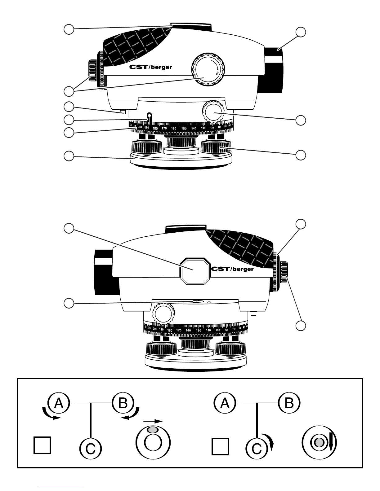
FEATURES (Fig. 1)
1. Base Plate
2. Horizontal Circle 8. Horizontal Drive Screw
3. Horizontal Circle Reference Mark 9. Leveling Screw
4. Compensator Lock 10. Circuclar Bubble Vial
5. Focusing Knobs 11. Vial Sighting Prism
6. Optical Peep Sight 12. Eyepiece Cover
7. Sunshade / Objective Lens 13. Eyepiece Focusing Knob
FEATURES
• Wire-hung, magnetically dampened compensator for optimum range
and accuracy.
• Compensator lock protects instrument during transport or storage; the
lock can also be used as a handy compensator checking tool.
• Large effective aperture and minimum focus of 0.3 m.
• Top-mounted optical peep-sight for quick reference.
• Large, easy-to-use precise focusing knob.
• Easy-to-read horizontal circle.
• Prism for easy bubble viewing.
• Sealed, dust-protected leveling screws.
• Water resistant, sealed construction plus sunshade for use in various
weather conditions.
• Fine adjustment knobs on left and right sides with friction-braked rota-
tion, endless horizontal drive.
• 1:100 stadia for distance estimation.
• 5/8” x 11 threads to fit standard tripods.
EN

INTRODUCTION
Thank You for purchasing one of our Automatic Levels.
This manual includes specifications for the PAL and SAL”N” series auto
level. This instrument was carefully inspected and calibrated within tight tol-
erances before shipment. We properly package the instruments for ship-
ment, but we cannot control how the package is handled during shipment.
We advise that you check the instrument using the test shown in the Chapter
“Line-of-Sight” before using. “Measure Twice, Cut Once”...
After doing any job using any instrument, it is advised that you check your
work. To check your work, set up the instrument in a different location from
the place where you originally set up (approx. 16 m) and reshoot a few of
your original targets. The new readings should agree with the first readings.
If the new readings do not agree, you should have the instrument checked
by a CST/berger Authorized Repair Center, or try the Line-of-sight adjust-
ment.
USING THE INSTRUMENT
Setting up the instrument and centering the bubble
1. Set up the tripod and attach the level using the tripod mounting screw.
2. Adjust the tripod legs until the tripod head is roughly level. Center the
bubble within the vial by turning the leveling screws as shown in Fig. 2.
2a – Turn screws A and B to move the bubble to the right side.
2b – Turn screw C to center the bubble.
4 • PAL/SALN AutoLevel

Focusing the instrument
1. Focus the cross hairs (Fig. 3) by pointing the telescope towards a bright
background or holding a white sheet of paper in front of the objective
lens, then turning the eyepiece until the cross hairs are sharp and
black.
2. Focus the telescope by locating a target, such as a leveling rod, using
the optical peep sight. Looking through the eyepiece, use the focusing
knob to bring the target into sharp focus. Center the vertical hair within
the target using the horizontal drive knobs on either side of the instru-
ment.
Reading measurements using a leveling rod
Height reading
Read the rod where it is intersected by the horizontal hair. For example, the
height reading in Fig. 4 (Fig. 4/a) is 2.0 ft (1,195 m).
Distance measurement
Read the rod where it is intersected by the upper and lower stadia hairs; in
Fig. 4 (Fig. 4/a) these readings are at 1.9 ft and 2.1 ft (1,352 m and 1,038 m).
The stadia ratio is 1:100; therefore, the distance from the instrument to the
rod is: (2.1 - 1.9) x 100 = 20 feet - Fig. 4/a (1,352 – 1,038) x 100 = 31,41 m.
Angle measurement
As shown in Fig. 5, sight point A and rotate the horizontal circle until the ref-
erence mark is on “0”. Rotate the level and sight point B; the reference mark
will indicate the angle between A and B.
PAL/SALN AutoLevel • 5

CALIBRATION
Your Automatic Level has been factory calibrated; however, you should
occasionally check your level for errors caused by shipment or rough han-
dling.
Compensator lock button
Check the compensator for proper operation before use or anytime the oper-
ation of the instrument is in question. Push and release the compensator
lock button to shake the compensator. The compensator should return to the
exact horizontal position sighted before the lock button was pressed.
Circular bubble vial
Center the vial bubble using the leveling screws, then rotate the instrument
180°. The bubble should remain centered (Fig. 6). If the bubble moves out of
center, the vial needs adjustment (Fig. 7).
Turn the leveling screws to bring the bubble halfway to center (Fig. 8). Using
the Allen wrench, turn the two vial adjustment screws to center the bubble
(Fig. 9).
Repeat the above procedure until the bubble remains centered when the
level is rotated 180°.
Line-Of-Sight
The line-of-sight needs to be horizontal within 3 mm of level to be accurate.
Set up and level the instrument on a tripod midway between two leveling
rods set approximately 30m to 50m apart. Sight rods A and B; the height
readings are a1 and b1 (Fig. 10). The value “H” is equal to (a1 – b1). Move the
instrument to within 6 feet (2m) of rod A and re-level. Again sight rods A and
6 • PAL/SALN AutoLevel

PAL/SALN AutoLevel • 7
B; these height readings are a2 and b2 (Fig. 11).
If a1 – b1 = a2 – b2 = H, the line-of-sight is horizontal. If not, the level should
be adjusted as follows.
Because the instrument is set halfway between A and B, any error in the
line-of-sight causes both readings to be erroneous by the same amount.
Error “e” cancels out, so the value a1 – b1 = H is correct. Therefore, a2 – H =
b3, the adjusting value.
To adjust, unscrew the eyepiece cover. Turn the adjusting screw with the
adjusting pin (Fig. 12) until the horizontal cross hair gives the reading b3, on
rod B. Repeat the above Procedure until {(a1-b1) – (a2-b2)} </= 3 mm.
MAINTENANCE
Care must be taken to maintain the accuracy of the instrument.
• After each use, the instrument should be wiped clean and kept in its
carrying case.
• Remove dust from the lenses with a soft brush or a nonabrasive wipe.
Never touch the lenses with your fingers.
• Store the instrument in a dust-free area with low humidity.
• A bag of silica gel dryer is included with each instrument; if it has
stopped working effectively, bake it to remove moisture or replace with
a new bag.
• Any damage to the instrument must be repaired by a
CST/berger Authorized Service Center.

8 • PAL/SALN AutoLevel
TECHNICAL DATA
MMooddeellSSAALL2200NNSSAALL2244NNSSAALL2288NNSSAALL3322NNPPAALL2222PPAALL2266
MMaaggnniiffiicc..::20 x 24 x 28 x 32 x 22 x 26 x
L
Leevveelliinngg::1/8”@100’ 1/16”@150’ 1/16”@200’ 1/16”@250’ 3/32”@150’ 1/16”@200’
aaccccuurraaccyy(3mm/30m)(1,6mm/45m)(1,6mm/60m) (1,6mm/75m)(2,4mm/45m) (1,6mm/60m)
W
Woorrkkiinngg::200’ 300’ 350’ 400’ 300’ 350’
rraannggee(60 m) (90 m) (105 m) (120 m) (90 m) (105 m)
C
Clleeaarroobbjj..::36mm 36mm 40mm 40mm 36 mm 40 mm
aappeerrttuurree
SSeettttiinngg::+/- 0.8” +/- 0.8” +/- 0.5” +/- 0.3” +/- 0.8” +/- 0.5”
aaccccuurraaccyy
S
St
ta
an
nd
da
ar
rd
d:
:2.5mm 2.0mm 1.5mm 1.0mm 2.0mm 1.5mm
d
de
ev
vi
ia
at
ti
io
on
nfor 1 km double-run leveling
T
Teelleessccooppee::
Image: erect Length: 8”(202mm) Shortest focusing distance: 1’ (0.3m)
Field of view : 1°20’ Stadia ratio: 100 Stadia addition: 0
C
Coommppeennssaattoorr::
Leveling range: +/- 15’ Magnet dampening: Yes
SSeennssiittiivviittyyooffbbuubbbbllee::8’/2mm
CCiirrcclleeggrraadduuaattiioonn::1° or 1 gon
WWaatteerrrreessiissttaanntt::Yes
IInnssttrruummeennttnneettwweeiigghhtt::1.8kg (4 lbs)
M
Moouunnttiinnggtthhrreeaadd::5/8“ x 11

WARRANTY
Five Year Warranty. CST/berger, a division of Stanley Works, warrants this
instrument against defects in material and workmanship for a period of five
years from the date of purchase. Deficient products will be repaired or
replaced at CST/berger's discretion. For warranty and repair information,
contact you local distributor.
For U.S., before returning the instrument to CST/berger, please
call (815) 432-5237 for a Return Authorization Number from our
Customer Service Department.
CST/berger's liability under this warranty is limited to repair or replacement
of the unit. Any attempt to repair the product by other thanfactory authorized
personnel will void this warranty. Calibration and maintenance are the
responsibility of the user. Where permitted by law, CST/berger is not respon-
sible for incidental or consequential damages.
Agents of CST/berger cannot change this warranty. CST/berger is not
responsible for damage resulting from wear, abuse, or alteration of this prod-
uct. The user is expected to follow ALL operating instructions.
This warranty may provide you with additional rights that vary by state,
province or nation.
IMPORTANT NOTE: The customer is responsible for the correct use and care
of the instrument. Moreover he is completely responsible for checking the
job along its prosecution, and therefore for the calibration of the instrument.
Calibration and care are not covered by warranty.
Subject to change without notice
PAL/SALN AutoLevel • 9

DESCRIPCIÓN DE LAS PARTES (Fig. 1)
1. Base 2. Círculo horizontal
3. Referencia para la graduación horizontal
4. Bloqueo del compensador 5. Enfoque del objetivo
6. Mira del objetivo ó punto de mira 7. Protector solar del ocular
8. Tornillos de movimiento horizontal 9. Tornillos de nivelación
10. Nivel esférico 11. Visor del nivel esferico
12 Protección del ocular 13. Enfoque del ocular
CARACTERISTICAS
• Péndulo compensador suspendido de amortiguación magnética provee
gran estabilidad y precisión.
• El bloqueo del compensador protege el instrumento durante el trans-
porte; el bloqueo se puede también utilizar para comprobar el fun-
cionamiento del compensador.
• Gran apertura efectiva y distancia de enfoque mínima de 0,3 m.
• Punto de mira puesto sobre el telescopio.
• Círculo horizontal exterior visible.
• Visor del nivel esferico
• Tornillos de nivelación protegidos contra agua y polvo
• Resistente al agua y al polvo
• Tornillos de movimiento fino situados a ambos lados con rotación frena-
da por fricción, rotación horizontal sinfín.
10 • PAL/SALN AutoLevel
E

INTRODUCCIÓN
Gracias por haber escogido uno de nuestros Niveles Ópticos.
Este manual de instrucciones incluye las caracteristicas y la utilización para
los niveles ópticos de la serie 55-PAL y 55-SAL-N. Viene también incluido
con la serie 55-SAL, que tiene las mismas specificaciones e instrucciones de
uso, con la excepción que los niveles ópticos de la serie 55-SAL incorporan
un compensador mecánico en lugar que magnético. El resto de datos técni-
cos son iguales.
Nuestros instrumentos están controlados y calibrados en fábrica; y al mismo
tiempo enviados en un embalaje muy seguro. Sin embargo no podemos con-
trolar los intrumentos durante el transporte. Por esta razón se recomienda
hacer una prueba de calibración antes de utilizar el instrumento, siguiendo
las instrucciones descritas en el capítulo “ Línea de vista”.
Después de cualquier trabajo con cualquier instrumento, se aconseja com-
probar siempre el trabajo. Colocar el instrumento en un lugar distinto, aproxi-
madamente a 16 m del lugar inicial, y tomar otra vez algunas de las lecturas
iniciales. Estas nuevas lecturas tienen que ser iguales a las primeras. Si no
es así, puede intentar calibrar el instrumento según las indicaciones
descritas en el capítulo “ Línea de vista”, o ponerse en contacto con su
proveedor o con un centro de Servicio Autorizado CST/Berger.
UTILIZACIÓN DEL INSTRUMENTO
Ajuste del instrumento y nivelación de la burbuja
1. Colocar el trípode sobre el punto de referencia en el suelo y bloquear
las patas. Montar el nivel en el trípode y atornillarlo.
2. Bloquear las patas del trípode de forma que la cabeza del trípode está
bien nivelada. Centrar la burbuja utilizando los tornillos de nivelación
como indicado en la Fig. 2.
PAL/SALN AutoLevel • 11

2a - Utilizar los tornillos de ajuste A y B para centrar la burbuja esférica
de la izquierda a la derecha.
2b – Utilizar el tornillo de ajuste C para mover la burbuja esférica hacia
el centro.
Enfoque del anteojo
1. Apuntar el anteojo a una zona clara o sujetando un papel blanco
enfrente del objetivo, y mover el ocular hasta que el retículo esté bien
enfocado (Fig. 3).
2. Enfocar el telescopio localizando un objeto, por ej. una mira con la
ayuda del punto de mira. Mirando a traves del ocular, utilizar el enfoque
del objetivo para enfocar la mira. Centrar el hilo vertical dentro del
objeto, utilizando uno de los tornillos de movimiento horizontal.
Lecturas de la mira
Medición de alturas
Tomar la lectura de la mira en el punto donde el hilo horizontal la atraviesa.
Por ejemplo, en la Fig. 4 (Fig. 4/a) la medición de la altura es
2.0 pies (1,195 m).
Medición de distancia
Tomar la lectura de la mira donde los hilos del retículo de cuña la
atraviesan. Por ejemplo, en la Fig. 4 (Fig. 4/a) esas mediciones son 1.9 y 2.1
pies (1,352 m y 1,038 m). La constante estadimétrica es 1:100; por consigu-
iente la distancia entre la mira y el instrumento es (2.1 – 1.9) x 100 = 20 pies –
Fig. 4/a (1,352 – 1,038) x 100 = 31,41 m.
Medición de ángulos
Como indicado en la Fig. 5 apuntar al objetivo “A” y girar el círculo horizontal
hasta que la referencia se encuentre en el punto 0. Luego apuntar al objetivo
“B”; la referencia del círculo horizontal indicará el ángulo que se ha creado
entre A y B.
12 • PAL/SALN AutoLevel

CALIBRACIÓN
Todos los instrumentos están calibrados durante el montaje y control de cal-
idad; sin embargo el usuario tiene que controlar la calibración a intervalos
regulares y también antes de efectuar medidas importantes, porque los
parámetros pueden variar con el tiempo o con el trasporte.
Bloqueo del compensador
Comprobar el correcto funcionamiento del compensador antes del trabajo o
cada vez se tenga duda sobre su correcto funcionamiento. Presionar y soltar
el bloqueo para mover el compensador. El compensador tiene que volver a la
misma posición horizontal donde se encontraba antes de presionar el blo-
queo.
Nivel esférico
Centrar la burbuja utilizando los tornillos de nivelación, luego girar el instru-
mento 200°
°. La burbuja tiene que estar todavía centrada (Fig. 6). En caso
contrario, hay que calibrar el nivel esférico (Fig. 7).
Utilizar los tornillos de nivelación para llevar la burbuja a medio camino
hacia el centro (Fig. 8). Utilizando la llave de ajuste que se encuentre en el
maletín, girar los dos tornillos para centrar la burbuja (Fig. 9).
Repetir este procedimiento, hasta que la burbuja permanezca centrada,
cuando se gire el instrumento 200°
°.
Línea de vista
La Línea de vista tiene que ser horizontal dentro de 3 mm para ser precisa.
Montar el nivel optico en un trípode a medio camino entre dos miras puestas
a una distancia de aprox. 30 – 50 m. Nivelar el instrumento. Apuntar las
miras A y B; las lecturas de la altura son a1 y b1 (Fig. 10). H es igual a (a1-
b1). Mover el instrumento hasta 2 m de distancia de la mira A y volver a
nivelarlo. Apuntar de nuevo las miras A y B; esas lecturas serán a2 y
b2 (Fig. 11).
PAL/SALN AutoLevel • 13

Si a1-b1 = a2-b2 = H, la line-of-Sight está horizontal. En caso contrario ajus-
tar el nivel como sigue.
Como el instrumento está a medio camino entre A y B, el error en la linea
visual causa error de lectura a ambos lados.El error se cancela fuera, con
el valor a1-b1 = H es correcto. Por lo tanto
a2 - H = b3, que es el valor de ajuste.
Para calibrar, desattornillar la protección del ocular. Girar el tornillo de
ajuste con la llave (Fig. 12), hasta que el hilo horizontal da la lectura b3 sobre
la mira B. Repetir este procedimiento hasta que {(a1-b1) – (a2-b2)} </= 3mm.
MANTENIMIENTO Y CONSERVACIÓN
•Después del uso, limpiar el instrumento utilizando un paño suave y seco
para eliminar la humedad. - No utilizar ni detergentes ni disolventes
agresivos.
• Guardar el nivel en su maletín cuando no vaya a usarlo, en un lugar sin
polvo y sin humedad.
• En el maletín hay también una bolsa de SILICA GEL; si el equipo deja de
funcionar mucho tiempo, sáquelo del estuche y sustituya la bolsita de
silica.
• Cualquier avería, reparación o calibración ha de ser realizada en un
servicio autorizado CST/Berger.
DATOS TÉCNICOS
MMooddeellooSSAALL2200NNSSAALL2244NNSSAALL2288NNSSAALL3322NNPPAALL2222PPAALL2266
AAuummeennttooss::20X 24X 28X 32X 22X 26X
P
Prreecciissiióónn::1/8”/100’ 1/16”/150’ 1/16”/200’ 1/16”/250’ 3/32”/150’ 1/16”/200’
(3mm/30m) (1,6mm/45m) (1,6mm/60m) (1,6mm/75m) (2,4mm/45m) (1,6mm/60m)
AAllccaannccee::200 pies 300 pies 350 pies 400 pies 300 pies 350 pies
(60 m) (90 m) (105 m) (120 m) (105 m)
AAppeerrttuurraa: 36 mm 36 mm 40 mm 40 mm 36 mm 40 mm
14 • PAL/SALN AutoLevel

eeffeeccttiivvaa
EExxaaccttiittuudd::+/-0,8” +/-0,8” +/-0,5” +/-0,5” +/-0,8” +/-0,5”
ddeeeessttaabbiilliizzaacciióónn
P
Prreecciissiióónnddeell::2,5 mm 2,0 mm 1,5 mm 1,0 mm 2,0 mm 1,5 mm
c
coommppeennssaaddoorreennddoobblleenniivveellaacciióónnddee11kkmm
TTeelleessccooppiioo::
Imagen: Directa Longitud: 8 pul. (202 mm) Dist. de enfoque mín.: 1’ (0,3 m)
Campo de visión: 1°20’ Constante estadimétrica: 100 Constante de adición: 0
N
Niivveellaacciióónnaauuttoommaattiiccaa::
Margen de compensación: +/-15’ Amortiguación magnética: Si
SSeennssiibbiilliiddaaddnniivveelleessfféérriiccoo::8’/2 mm
GGrraadduuaacciióónnddeellcciirrccuulloohhoorriizzoonnttaall::cada 1° o 1 gon
RReessiisstteenntteeaallaagguuaa::Si
PPeessoossóóllooiinnssttrruummeennttoo::4 libras (1,8 kg)
R
Roossccaappaarraattrrííppooddee::5/8”x11
GARANTÍA
CST/Berger a division of Stanley Works, garantiza sus instrumentos de
medición contra deficiencias en materiales o mano de obra durante cinco
años a partir de la fecha de compra.
Los productos defectuosos serán reparados o reemplazados, a elección de
CST/Berger, tras ser recibidos junto con su prueba de compra.
Para información sobre garantía y reparación, contactar:
d
di
is
st
tr
ri
ib
bu
ui
id
do
or
rl
lo
oc
ca
al
l,
,o
oC
CS
ST
T/
/B
BE
ER
RG
GE
ER
R.
Para E.E.U.U., antes de devolver el instrumento a CST/Berger, por favor lla-
mar al (815)432-5237 para un Número de Autorización de Devolución del
Departamento de Atención al Cliente.
Esta garantía no cubre deficiencias causadas por daños accidentales, des-
gaste por el uso o usos diferentes de los indicados por el fabricante o
PAL/SALN AutoLevel • 15

reparaciones o alteraciones de estos productos no autoriza
das por CST/Berger.
Cualquier reparación o reemplazo durante la vigencia de esta Garantía no
afecta a su fecha de vencimiento.
Dentro de lo autorizado por la legislación vigente, CST/Berger no se obliga
por esta Garantía a compensar pérdidas como resultado de deficiencias en
el producto.
Nada de lo establecido en esta Garantía limitará la responsabilidad de
CST/Berger para con los compradores en caso de (1) muerte o daños per-
sonales causados por su negligencia o (2) mala conducta intencionada o
gran negligencia.
Esta Garantía no puede ser alterada sin la autorización de CST/Berger.
Esta Garantía no afecta a los derechos implícitos de los compradores de
estos productos.
N
NO
OT
TA
AI
IM
MP
PO
OR
RT
TA
AN
NT
TE
E:
:
El comprador es responsable del correcto uso y mantenimiento del instru-
mento. Y además es de su responsabilidad controlar la buena ejecución del
trabajo y por consiguiente la calibración del instrumento. Mantenimiento y
calibración no están en garantía.
CST/Berger se reserva el derecho de aportar modificaciones técnicas sin
previo aviso.
16 • PAL/SALN AutoLevel

ELEMENTS COMPOSANT L’APPAREIL (Fig.1)
1. Embase
2. Cercle horizontal 3. Repère du cercle gradué
4. Blocage du compensateur 5. Boutons de mise au point
6. Viseur optique 7. Objectif
8. Vis de mouvement fin 9. Vis calante
10. Nivelle circulaire 11. Miroir de renvoi de nivelle
12. Bonnette d’oculaire 13. Oculaire
LES PLUS TECHNIQUES
• Compensateur avec fils croisés pour une meilleure précision.
• Grande ouverture d’objectif et une distance de visée minimale de 0,3 m.
• Viseur optique pour une estimation rapide.
• Large bouton de mise au point.
• Lecture facile du cercle horizontal.
• Blocage du compensateur lors de transport.
• Miroir de renvoi de nivelle.
• Vis calantes traitées anti-poussière.
• Etanche et isolé pour un travail dans des conditions difficiles.
• Possibilité d’estimation de distances.
• Filetage 5/8”x 11 standard pour adaptation sur tous types de trépied.
PAL/SALN AutoLevel • 17
F

INTRODUCTION
Merci d’avoir choisi une de nos nivelles optiques.
Ce manuel regroupe les spécifications techniques des niveaux automatiques
55-PAL et 55-SAL-N.
Avant de quitter notre usine, ces instruments ont fait l’objet d’un contrôle et
d’un réglage précis. De plus, ils sont expédiés dans des emballages spé-
cialement conçus pour le transport. Malgré ces précautions, il nous est
impossible d’assurer qu’ils seront à l’abri de tout dommage pendant
le transport.
Aussi est-il conseillé de contrôler l’appareil avant toute utilisation selon la
procédure décrite au chapitre “ Nivellement de contrôle”.
Après utilisation de l’appareil, il est conseillé de contrôler le résultat obtenu.
Positionner l’appareil à un endroit différent de sa position initiale, à environ
16 m de distance et reprendre certaines des mesures. Les nouvelles lectures
doivent correspondre aux précédentes. S’il n’en est pas ainsi, régler l’ap-
pareil en suivant les indications du chapitre “Nivellement de contrôle” ou
encore contacter le revendeur le plus proche ou le service après-vente
agréé CST/Berger.
UTILISATION DE L’APPAREIL
Mise sur trépied et réglage de la nivelle sphérique
1. Fixer le niveau sur le trépied à l’aide de la pompe orange située vers le
plateau du trépied.
2. Régler la nivelle sphérique à l’aide des 3 vis calantes selon la manière
décrite ci-dessous en Fig. 2.
2a – Tourner simultanément et en sens opposé les vis calantes A et B
jusqu’à ce que la bulle se trouve sur un T imaginaire.
2b – Amener ensuite la bulle au centre de son cercle repère à l’aide de
la vis calante C.
18 • PAL/SALN AutoLevel

Mise au point de la lunette de visée
1. Orienter la lunette en direction du jour en plaçant devant l’objectif une
feuille de papier blanc. Tourner l’oculaire jusqu’à ce que le réticule soit
net bien noir (Fig. 3).
2. A l’aide du viseur située au-dessus de l’appareil, pointer l’instrument
sur la mire placée sur le point à relever. Tourner le bouton de réglage
situé sur le côté droit de la lunette afin d’obtenir une mise au point cor-
recte. Pour régler la lunette dans l’axe de la mire, tourner les vis de
mouvement fin situées à droite et a gauche de l’appareil.
Lecture sur la mire
Lecture en hauteur
Lire la position du fil horizontal du milieu sur l’image de la mire. La hauteur
lue sur l’exemple en Fig. 4/a (Fig. 4) est de 1,195 m (2.0 pi).
Estimation de distance
Lire les deux fils stadimétriques extrêmes hauts et bas. Faire la différence
entre la lecture d’en haut et la lecture d’en bas. Vous obtenez une valeur que
vous multipliez par 100. En Fig. 4/b: (1,352 m – 1,038 m) x 100 = 31,40 m. En Fig.
4: (2.1 – 1.9) x 100 = 20 pieds
Mesure d’angles
Comme indiqué en Fig. 5, viser le point A et tourner le cercle horizontal
jusqu’à ce que le repère situé sur le corps du niveau soit en face du 0 du
cercle puis tourner le niveau pour viser le point B. Lire la valeur de l’angle
AB au repère.
PAL/SALN AutoLevel • 19

RÉGLAGE
Le niveau automatique vous est livré réglé et contrôlé usine. Toutefois de
petits déréglages peuvent intervenir lors de manipulations hasardeuses ou
de transport chaotique.
Touche de blocage du compensateur.
Vérifier le compensateur avant de l’utiliser. Appuyer sur la touche de
blocage et la relâcher pour actionner le compensateur. Celui-ci doit revenir
exactement à la position horizontale qu’il occupait avant que la touche de
blocage ne soit enfoncée.
Nivelle circulaire
Centrer la bulle et tourner l’instrument de 200 g. La nivelle ne doit pas bouger
de son centre (Fig. 6). Si la bulle s’est décentrée, vous devez la régler (Fig. 7).
Tourner les vis calantes pour éliminer la moitié de l’écart (Fig. 8). Enlever
l’autre moitié de l’écart à l’aide de votre clé (Fig. 9). En vissant, la bulle se
déplace en direction de cette vis. En dévissant, elle s’en éloigne.
Nivellement de contrôle
Choisir un point stable A et B. A et B doivent être distants de 30 à 50 m.
Placer l’instrument au milieu de ces 2 points. Lire les hauteurs sur la mire A
et B et faire la différence de hauteur (Fig. 10). La valeur H = a1 – b1.
Mettre alors l’instrument à 2 m de la mire A et recaler l’instrument. Lire alors
la lecture sur la mire A et la mire B. Les hauteurs lues sont a2 et b2 (Fig. 11).
Si a1 – b1 =a2 – b2 = H, alors le réglage est bon. Sinon, le niveau doit être
ajusté selon la méthode ci-dessous.
Prenez la valeur H = a1 – b1. Il va falloir régler la lunette avec la
valeur b3 = a2 – H.
20 • PAL/SALN AutoLevel
Other manuals for SAL20N
1
This manual suits for next models
5
Table of contents
Languages:
Other CST/BERGER Tools manuals


