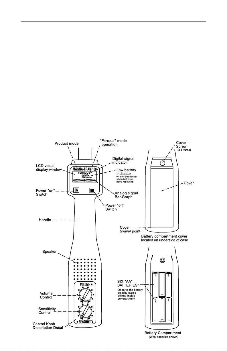
CST Magna-Trak MT102 User manual

1
INSTRUCTION MANUAL
Magna-Trak 100®
Magnetic Locator

2
Thank you for purchasing the Magna-Trak 100®Magnetic Locator. Please read this
manual thoroughly before operation.
CONTENTS
1. Introduction .............................................................................................................. 3
2. Theory of Operation ................................................................................................ 3
3. Features......................................................................................................................4
4. Basic Operation and Description .......................................................................... 5
4.1 Power ON/OFF Switches .............................................................................................5
4.2 Volume and Sensitivity Control Knobs ....................................................................... 5
4.3 Speaker .........................................................................................................................5
4.4 LCD Visual Display ........................................................................................................5
5. Battery Replacement ..............................................................................................6
6. Field Operation ......................................................................................................... 7
6.1 Water Locations ...........................................................................................................8
6.2 Locating Near a Steel Fence .......................................................................................8
7. Signal Response ........................................................................................................9
7.1 Typical Signal Responses ...........................................................................................10
8. Specifications ..........................................................................................................11
9. Warranty & Service ................................................................................................ 11
450 S. CIPS Street • P.O. Box 359
Watseka, IL 60970 USA
(815) 432-5237 Toll Free US: (800) 435-1859
FAX (815) 432-2417
http://www.cstsurvey.com
Chicago Steel Tape Berger Instruments Magna-Trak®LaserMark®Tru-Lock™
Printed in USA GG4982000

3
1. INTRODUCTION
The Magna-Trak 100®magnetic locator is a flux-gate type of magnetometer which
incorporates a unique patented technology that enables the factory to balance the
magnetic sensing coils to a finite condition. This patented method of magnetic
balancing is advanced in the state of the technology.
The Magna-Trak 100 implements “peak response” over ferromagnetic objects by
yielding an increasing audio signal as the object is approached and passed over.
This instrument is the product of many years of experience and service provided by
CST to the industry.
2. THEORY OF OPERATION
The Magna-Trak 100 locator finds ferromagnetic objects by sensing the magnetic field
radiated by the object. The locator contains two sensor coil assemblies that are
precisely spaced and electronically balanced to achieve a near magnetically-balanced
operating condition. In a uniform magnetic field, such as the earth’s field, the two
sensor coils maintain a magnetically-balanced status, because both of the coils
experience the same magnetic lines of force. However, when a ferromagnetic object
is approached, the field strength and angle of the magnetic lines upon each sensor is
different. This difference, although minute, is enough to offset the critical balance
and produce an audible indicating signal (Fig. 1).
When no ferromagnetic objects are present, the speaker emits a steady low fre-
quency tone. As the object is approached, the audio frequency increases until the
center of the object is directly beneath the locator’s lower tip sensor. The frequency
peaks and then decreases as the object is passed. The peak indicates the exact
location of the object.
Nonferrous objects do not affect the locator. Objects made of brass, aluminum,
copper, etc. are ignored.
a
a
a
a
a
a
a
aa
a
aa
aaa
a
a
a
a
a
a
a
aa
a
a
aa
a
a
a
a
a
aa
aa
a
a
a
a
aa
a
a
a
a
a
a
a
a
a
a
a
a
a
a
a
aa
a
a
a
a
a
a
a
a
a
a
a
a
a
a
a
a
a
a
a
a
a
a
a
a
a
a
aa
a
a
a
a
a
a
a
a
a
a
a
a
a
a
a
a
a
a
a
a
a
a
a
a
a
a
a
a
aa
a
aa
a
a
a
a
a
aaa
a
aa
a
a
a
a
aa
a
a
a
a
a
a
a
a
a
a
a
a
a
aa
aa
a
a
aa
a
a
a
a
a
a
a
a
a
aa
a
a
aa
a
a
aaa
a
a
a
a
a
a
a
a
a
a
a
a
a
a
a
a
a
a
a
a
a
a
a
a
a
a
a
a
a
a
a
a
a
a
a
a
a
a
a
a
a
a
a
a
a
a
a
a
a
a
a
a
a
a
a
a
a
a
a
a
a
a
a
a
a
a
a
a
a
a
a
a
aa
a
a
a
a
a
a
a
aa
a
a
a
a
a
a
a
a
a
aa
a
a
a
a
a
a
a
a
a
a
a
a
a
a
a
a
a
a
a
a
aaa
a
a
a
a
a
a
a
a
a
a
a
a
aa
a
a
a
a
a
a
a
aaa
a
a
a
a
a
a
a
a
aa
a
a
aa
a
aa
a
a
a
a
a
a
aa
aaa
a
a
a
a
a
a
a
a
a
a
a
a
a
a
a
a
a
a
a
a
a
a
a
a
a
a
a
a
a
aaa
a
a
a
a
a
a
a
a
aaa
a
aaa
a
a
a
a
a
a
aaa
a
a
a
a
a
aa
a
a
a
a
a
a
a
a
a
a
a
aaa
a
a
a
a
a
a
a
a
aaa
a
a
a
a
a
a
a
aa
a
a
a
a
a
a
a
a
a
a
a
a
a
a
a
a
a
a
a
a
a
a
a
a
a
a
a
aaa
a
a
a
a
a
a
a
a
a
a
a
a
a
a
a
a
a
a
a
a
a
aaa
a
aa
a
a
a
a
a
a
a
a
a
a
a
a
a
a
a
a
a
a
a
a
a
a
a
a
a
a
a
a
aa
a
a
a
a
a
a
a
a
a
a
a
a
a
a
a
a
a
a
a
a
a
a
a
a
a
a
a
a
a
a
a
a
a
a
a
a
a
a
aa
a
a
aa
a
a
a
a
a
a
a
a
a
a
a
a
a
a
a
a
a
a
a
a
a
a
a
a
a
a
a
a
a
a
a
a
aa
a
a
aaa
a
a
a
aaaa
a
a
a
a
a
a
a
a
a
a
a
a
a
a
a
a
a
a
a
a
a
a
a
a
a
a
a
a
a
a
aa
a
a
a
a
a
a
a
a
a
a
a
a
a
a
a
a
a
a
a
a
a
a
a
a
a
a
a
a
a
a
a
a
a
a
a
a
a
aa
a
a
a
a
a
a
a
a
a
a
a
a
a
a
a
a
a
a
a
a
a
a
a
a
a
a
a
a
a
aa
a
a
a
a
aa
a
a
a
a
a
a
a
a
aa
a
aa
a
a
a
a
a
a
a
a
a
a
a
a
aa
a
aa
aaa
a
a
a
a
a
a
a
a
a
a
a
a
aa
a
aa
aaa
a
a
a
a
a
a
a
a
a
a
a
a
a
a
a
aa
aa
magnetic
field upper sensor
tip sensor
iron stake
a
a
a
a
a
a
a
aa
a
aa
aaa
a
a
a
a
a
a
a
a
a
a
a
a
aa
a
aa
aaa
a
a
a
a
a
Fig. 1
Sensor coils unbalanced by magnetic field of iron stake.

4
3. FEATURES
• Rugged high-impact plastic enclosure with aluminum sensor pole
• Powerful magnetic speaker with waterproof Mylar cone
• Lightweight, comfortably balanced for easy handling
• Easy view LCD display for visual signal strength and battery information:
includes two digit numeric signal indicator, expanding analog Bar-Graph signal
indicator, and flashing “Low Battery” indicator
• Six “AA” (11⁄2volt) battery operation; ±100 hour battery life
• Quick-access battery compartment
• Adjustable sensitivity and volume controls
• Single hand touch-switch operation for power ON/OFF
• Deep tone audio under search conditions; signals “peak” over magnetic objects
• Full depth capability
• Includes padded carrying case with shoulder strap or hard case

5
4. BASIC OPERATION AND DESCRIPTION
4.1 Power On/Off Switches
Press “ON” once to activate the locator circuitry. Press “OFF” once to turn the battery
power off.
4.2 Volume and Sensitivity Control Knobs
Rotate the volume knob to the desired audio volume level. Full volume is achieved
when the knob is turned fully clockwise.
The sensitivity or depth range can be varied using the sensitivity knob. Maximum
range is provided at full clockwise rotation. The optimal setting is determined by each
particular application. Areas crowded with various undesired ferrous objects may
require a reduced sensitivity level. Deeply buried objects being searched will require a
higher sensitivity level.
A decal with markings for both the sensitivity and volume control knobs is provided
as a reference for future settings or comparisons.
4.3 Speaker
When no ferrous metal is present, the audio sound heard will be a low frequency
tone. As ferrous metals are approached, the audio tone will increase.
4.4 LCD Visual Display
Several visual display functions, provided for ease of operation, are defined below:
“Ferrous”
Defines the basic function of the locator as a ferrous locator (fixed indicator).
Digital Signal Indicator
A two digit numeric display shows the signal level as related to the audio signal
response being heard from the speaker. At the lowest signal level, when no ferrous
metal is present, a small number will be viewed (between “0” and “5”). As metal is
approached, the numbers will increase, reaching “99” at its maximum peak. Deeply
buried objects or lower sensitivity levels will yield a lower peak number to aid in
pinpointing the object.
Analog Bar-Graph Signal Indicator
The bar graph display expands outward from the center “diamond” as related to the
audio signal response being heard from the speaker.

6
5. BATTERY REPLACEMENT
The LCD will display a flashing “Low Battery” warning when the batteries fall below a
predetermined voltage level, alerting you to replace the batteries soon. Several hours
of battery life remain; however, in cold temperatures, this time may be shorter.
Replace the batteries as follows:
1:
Turn the power off.
2:
Unscrew the thumb screw on the battery cover (2-5 turns) and lift the cover off until
the tab at the rear of the cover clears the slot it is located in.
3:
Remove the batteries by raising the batteries at the contact point of each pair.
Dispose of used batteries properly.
4:
Insert new batteries, observing the polarity labels located inside the battery well.
NOTE: Do not mix old and new batteries. Replace all batteries at the same time
with new batteries. Also, do not replace the batteries under wet or rainy
conditions, allowing water to enter the battery compartment.
5:
Reinstall the cover in the reverse manner, being careful not to overtighten the thumb
screw.
In the event the “Low Battery” indicator is not displayed, no visual indications appear
on the LCD window and no sound is heard after pressing the power ON switch, the
batteries may be dead; check the battery compartment immediately. Dead batteries
should be removed immediately as they are prone to leakage and can cause perma-
nent damage.
Always remove batteries before storing your locator.

7
6. FIELD OPERATION
The recommended search position is a 45°angle from the earth’s surface. Scan the
locator pole from side-to-side in a slow sweeping motion while walking in a steady
direction. Maintain a consistent height above the ground during the side-to-side
sweeping motion.
Once the object being searched is located, pinpointing the object’s location can be
accomplished by holding the locator vertically and sweeping it in an “X” pattern until
the absolute signal peak is found (Fig. 2). The audio sound and visual LCD display will
provide the pinpointing results.
Please note that your magnetic locator is not only sensitive to buried ferrous objects,
but also to items in your possession. Ferrous objects such as steel tipped shoes, a
pocket knife, some wrist watches, key chains or other objects containing ferrous
material can cause false signals during your search.
The locator is not affected by the presence of nonferrous objects, such as copper,
aluminum pull tabs or foil, and other forms of trash that may be present in the
ground. Snow, ice, water, wood, plastic, concrete, stones, and the ground itself have
no effect on the performance of the locator.
Locator’s Electrical response
representation
Physical “X” Motion Shown
Fig. 2

8
6.1 Water Locations
The pole section of the locator can be submerged into water, up to just under the
plastic case (Fig. 3).
a
a
a
a
a
a
a
aa
a
aa
aaa
a
a
a
a
a
a
a
aa
a
a
aa
a
a
a
a
a
aa
aa
a
a
a
a
aa
a
a
a
a
a
a
a
a
a
a
a
a
a
a
a
aa
a
a
a
a
a
a
a
a
a
a
a
a
a
a
a
a
a
a
a
a
a
a
a
a
a
a
aa
a
a
a
a
a
a
a
a
a
a
a
a
a
a
a
a
a
a
a
a
a
a
a
a
a
a
a
a
aa
a
aa
a
a
a
a
a
aaa
a
aa
a
a
a
a
aa
a
a
a
a
a
a
a
a
a
a
a
a
a
aa
aa
a
a
aa
a
a
a
a
a
a
a
a
a
aa
a
a
aa
a
a
aaa
a
a
a
a
a
a
a
a
a
a
a
a
a
a
a
a
a
a
a
a
a
a
a
a
a
a
a
a
a
a
a
a
a
a
a
a
a
a
a
a
a
a
a
a
a
a
a
a
a
a
a
a
a
a
a
a
a
a
a
a
a
a
a
a
a
a
a
a
a
a
a
a
aa
a
a
a
a
a
a
a
aa
a
a
a
a
a
a
a
a
a
aa
a
a
a
a
a
a
a
a
a
a
a
a
a
a
a
a
a
a
a
a
aaa
a
a
a
a
a
a
a
a
a
a
a
a
aa
a
a
a
a
a
a
a
aaa
a
a
a
a
a
a
a
a
aa
a
a
aa
a
a
a
a
a
a
a
a
a
aa
aaa
a
a
a
a
a
a
a
a
a
a
a
a
a
a
a
a
a
a
a
a
a
a
a
a
a
a
a
a
a
aaa
a
a
a
a
a
a
a
a
aaa
a
aaa
a
a
a
a
a
a
aaa
a
a
a
a
a
aa
a
a
a
a
a
a
a
a
a
a
a
aaa
a
a
a
a
a
a
a
a
aaa
a
a
a
a
a
a
a
aa
a
a
a
a
a
a
a
a
a
a
a
a
a
a
a
a
a
a
a
a
a
a
a
a
a
a
a
aaa
a
a
a
a
a
a
a
a
aa
a
a
a
a
a
a
a
a
a
a
a
aaa
a
aa
a
a
a
a
a
a
a
a
a
a
a
a
a
a
a
a
a
a
a
a
a
a
a
a
a
a
a
a
aa
a
a
a
a
a
a
a
a
a
a
a
a
a
a
a
a
a
a
a
a
a
a
a
a
a
a
a
a
a
a
a
a
a
a
a
a
a
a
aa
a
a
aa
a
a
a
a
a
a
a
a
a
a
a
a
a
a
a
a
a
a
a
a
a
a
a
a
a
a
a
a
a
a
a
a
aa
a
a
aaa
a
a
a
aaaa
a
a
a
a
a
a
a
a
a
a
a
a
a
a
a
a
a
a
a
a
a
a
a
a
a
a
a
a
a
a
aa
a
a
a
a
a
a
a
a
a
a
a
a
a
a
a
a
a
a
a
a
a
a
a
a
a
a
a
a
a
a
a
a
a
a
a
a
a
aa
a
a
a
a
a
a
a
a
a
a
a
a
a
a
a
a
a
a
a
a
a
a
a
a
a
a
a
a
a
aa
a
a
a
a
aa
a
a
a
a
a
a
a
a
aa
a
aa
a
a
a
a
a
a
a
a
aa
a
a
a
a
a
a
a
a
a
a
a
a
aa
a
a
a
a
a
a
a
a
a
a
a
a
a
a
a
a
a
a
a
a
a
a
a
a
a
a
a
a
a
a
a
aa
aaaa
a
a
a
a
a
a
a
a
aa
a
a
a
a
a
a
a
a
aa
a
a
a
a
a
a
aaa
a
a
a
a
a
a
a
a
a
a
a
a
a
a
a
a
a
a
aa
a
a
a
a
a
a
a
aaa
a
a
aa
a
a
a
a
a
a
a
aaa
a
a
a
aa
a
a
a
a
a
a
a
a
a
a
a
a
a
a
a
a
a
a
a
a
a
a
a
a
a
a
a
a
a
a
a
a
a
a
a
a
a
a
a
a
a
aa
a
a
a
a
a
a
a
a
a
a
a
a
a
a
a
a
a
a
aa
a
a
a
a
a
a
a
a
a
a
aa
a
a
a
aa
a
a
aa
a
a
aaa
a
a
aaa
a
a
a
a
a
a
a
a
a
a
a
a
a
a
a
a
a
a
a
a
a
a
aa
a
a
a
a
a
a
a
a
a
a
a
a
a
a
a
a
a
a
a
a
a
a
a
a
a
a
a
a
aaa
a
a
a
a
aa
a
aa
a
a
a
a
aa
a
a
a
a
a
a
a
a
a
a
a
a
a
a
a
a
a
a
a
a
a
aa
a
a
a
a
a
a
a
a
a
a
aa
a
a
a
a
a
aa
a
a
a
a
a
a
a
a
a
a
a
a
a
a
a
a
aaa
aa
a
aa
a
aa
a
a
a
aa
a
aa
a
a
a
a
a
a
a
a
a
a
a
aaaa
a
a
a
a
a
a
a
a
a
a
a
a
a
a
a
aa
aa
a
a
a
a
a
a
a
a
a
a
a
a
a
a
aa
a
a
a
a
a
a
a
a
a
a
a
a
a
aa
a
a
a
a
a
a
aaa
a
a
a
a
aaaa
a
a
a
a
aa
a
a
a
a
a
a
a
aa
a
a
a
a
a
a
a
a
aa
a
a
a
a
a
a
a
a
a
a
a
a
aa
a
a
a
a
a
a
a
a
a
aaa
a
a
aa
a
aaaaa
a
a
a
a
a
a
a
a
aa
a
a
a
a
a
a
a
a
a
a
a
a
a
a
a
a
a
a
a
a
a
aa
a
a
a
aa
a
aa
a
a
a
a
a
a
aaa
a
aa
a
a
a
a
a
a
a
a
a
a
a
a
a
a
a
a
a
a
a
a
a
a
a
a
a
a
a
a
a
a
aa
a
a
a
a
a
a
a
a
a
a
a
a
a
a
aaaa
a
a
a
a
aaa
a
aa
a
a
a
a
a
a
a
a
aa
a
a
a
a
a
a
a
a
a
aa
a
a
a
a
aa
a
a
a
a
a
a
a
a
a
aaa
a
a
a
aa
a
a
a
aa
a
a
a
a
a
aa
a
a
a
a
a
a
a
6.2 Locating Near a Steel Fence
Move or slide the locator across the ground while holding the length of the locator
body perpendicular to the fence. Do not roll the locator on the ground. Maintain a
consistent distance between the tip of the locator and the fence.
The object will be directly below the tip of the locator (approx. 1⁄4" from the tip).
Fig. 3
Fig. 4
Buried iron stake
Consistent
distance
Slide locator
back and forth
Signal

9
a
a
a
a
a
a
a
aa
a
aa
aaa
a
a
a
a
a
a
a
aa
a
a
aa
a
a
a
a
a
aa
a
a
a
a
a
a
aa
a
a
a
a
a
a
a
a
a
a
a
a
a
a
a
aa
a
a
a
a
a
a
a
a
a
a
a
a
a
a
a
a
a
a
a
a
a
a
a
a
a
a
aa
a
a
a
a
a
a
a
a
a
a
a
a
a
a
a
a
a
a
a
a
a
a
a
a
a
a
a
a
aa
a
aa
a
a
a
a
a
aaa
a
aa
a
a
a
a
aa
a
a
a
a
a
a
a
a
a
a
a
a
a
aa
aa
a
a
aa
a
a
a
a
a
a
a
a
a
aa
a
a
aa
a
a
aaa
a
a
a
a
a
a
a
a
a
a
a
a
a
a
a
a
a
a
a
a
a
a
a
a
a
a
a
a
a
a
a
a
a
a
a
a
a
a
a
a
a
a
a
a
a
a
a
a
a
a
a
a
a
a
a
a
a
a
a
a
a
a
a
a
a
a
a
a
a
a
a
a
a
a
a
a
a
a
a
a
a
aa
a
a
a
a
a
a
a
a
a
aa
a
a
a
a
a
a
a
a
a
a
a
a
a
a
a
a
a
a
a
a
aaa
a
a
a
a
a
a
a
a
a
a
a
a
aa
a
a
a
a
a
a
a
aaa
a
a
a
a
a
a
a
a
aa
a
a
aa
a
aa
a
a
a
a
a
a
aa
aaa
a
a
a
a
a
a
a
a
a
a
a
a
a
a
a
a
a
a
a
a
a
a
a
a
a
a
a
a
a
aaa
a
a
a
a
a
a
a
a
aaa
a
aaa
a
7. SIGNAL RESPONSE
Figure 5 shows audio and LCD visual signal response to:
1: no object,
2: one small deeper metal target, and
3: a second larger and shallower metal object.
The LCD display indicates both the numeric digital and analog bar-graph response as
the locator passes over the ground.
(1) (2) (3)
Fig. 5

10
Sewer Cover
Signal Response
Signal Response
Signal Response
7.1 Typical Signal Responses
The metal handles on
the septic tank cover
will provide a usable
signal to determine
the location of the
actual cover (Fig. 6).
Large metal objects
may cause double
signals as indicated
(Fig. 7).
The center of the
cover is found by
sweeping the locator
back and forth to
create a ring pattern
response. The center
null will designate the
cover’s center.
The joints, elbows and ends of
iron pipes will create the
strongest signals (Fig. 8). Hold
the locator in a vertical
position while searching to
produce the best results.
Fig. 6
Fig. 7
Fig. 8

11
8. SPECIFICATIONS
Power: Six “AA” (11⁄2volt) batteries
Battery life: ±100 hours of intermittent operation (alkaline batteries)
Output: Powerful magnetic speaker with waterproof Mylar cone
LCD Display: Numeric digital, analog Bar-graph and low battery indicator feature
Weight: Approximately 3 lbs. (1.3kg) with batteries
Operating temperature: 0°F to 120°F (-18°C to 49°C)
Length: 40 inches (101.6 cm)
Construction: High-impact water resistant plastic, epoxy painted. Aluminum sensor
tube waterproof to just under the plastic case.
Patent: United States #4,439,732.
Nominal Sensor: 20 inches (50.8 cm)
Specifications subject to change without notice.
9. WARRANTY
The Magna-Trak 100® magnetic locator is warranted to be free from defects in
materials and workmanship for a period of five years after the delivery of the product
to the original user. Our liability under this warranty is limited to replacing any
defective parts, adjusting and servicing any instrument or, at the company’s option,
replacement of the instrument returned by the original user, transportation charges
prepaid, to the company. If the malfunction has been caused by misuse or abnormal
conditions of operation, repairs will be billed to the user, with a cost estimate
submitted prior to commencing repair work.
Batteries and the battery holder are not covered by this warranty.
All Magna-Trak 100 locators repaired out of warranty carry a warranty on replaced
parts for a period of 90 days.
Service
If your magnetic locator needs service, you may return it to the dealer from which it
was purchased or send it, transportation prepaid, directly to CST, 450 S. CIPS Street,
Watseka, IL 60970 USA. Include model number, serial number, proof and date of
purchase, your address and phone, and a written description of the problem
encountered with the instrument with the return of the locator.
Magna-Trak made in Watseka, Illinois, USA

12
450 S. CIPS Street • P.O. Box 359
Watseka, IL 60970 USA
(815) 432-5237 Toll Free US: (800) 435-1859
FAX (815) 432-2417
http://www.cstsurvey.com
Chicago Steel Tape Berger Instruments Magna-Trak®LaserMark®Tru-Lock™
This manual suits for next models
2
Table of contents
Other CST Measuring Instrument manuals