CTC Giersch RG20 Manual

Technical Information • Installation Instructions
Gas
Issued August 2019
Right reserved to effect technical changes
in the interest of product improvement !
RG20 / RG30
GB

2
E.04.99 • G. 08.08.19
Overview ........................................................................................................... 3
General information / safety information .................................................................................... 3
Checking scope of delivery and connection data....................................................................... 3
Operating instructions ................................................................................................................ 3
Instruction of operating personnel.............................................................................................. 3
Maintenance and customer service ........................................................................................... 3
Key for code designation ........................................................................................................... 4
Technical specifications ............................................................................................................. 4
Installation ......................................................................................................... 5
Installing flange and burner........................................................................................................ 5
Checking electrode setting......................................................................................................... 5
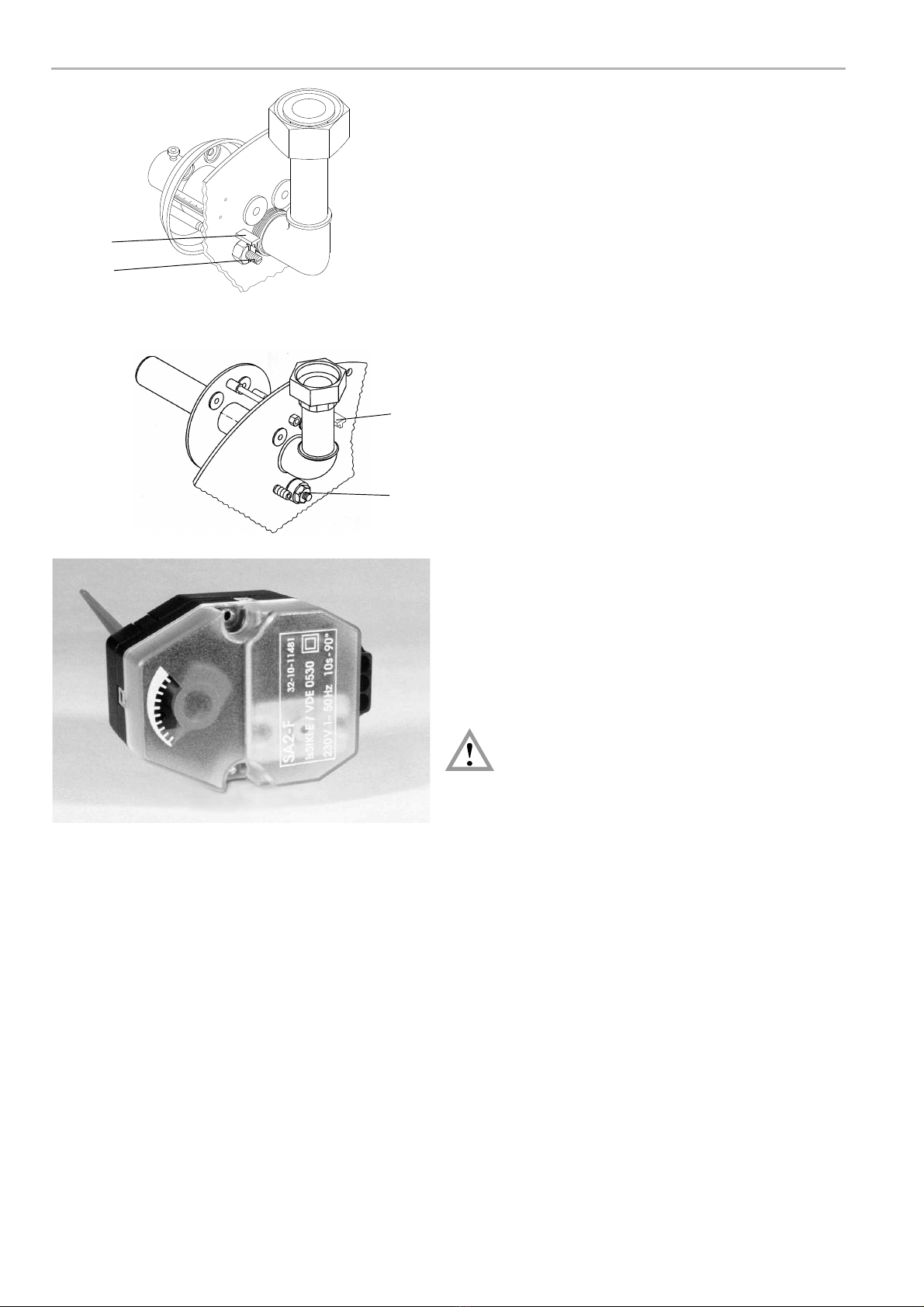
Installing gas assembly.............................................................................................................. 5
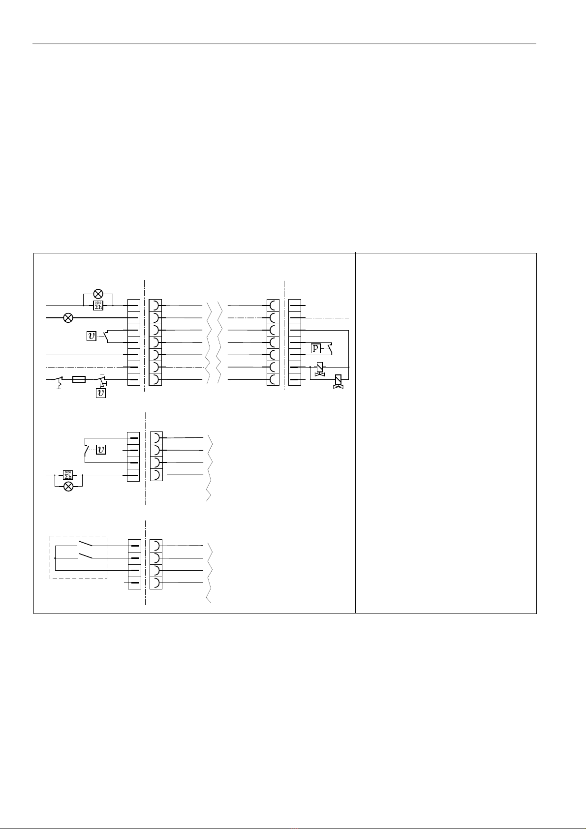
Establishing electrical connections ............................................................................................ 6
Function ............................................................................................................. 7
Control unit LME ........................................................................................................................ 7
Air flow setting, dimension “A”.................................................................................................... 10
Air flap positioning motor .......................................................................................................... 10
Compact gas unit ...................................................................................................................... 12
Gas pressure monitor ................................................................................................................ 12
Start-up .............................................................................................................. 13
Adjustment tables RG20 ............................................................................................................ 13
Adjustment tables RG30 ........................................................................................................... 15
Adjusting gas burner and boiler ................................................................................................. 17
Calculation principle for gas burner adjustment ......................................................................... 21
Design ............................................................................................................... 23
Exploded drawing and spare parts/parts list RG20.................................................................... 23
Exploded drawing and spare parts/parts list RG30.................................................................... 25
Service instructions/dimensions ........................................................................ 27
Service position.......................................................................................................................... 27
Reference dimensions, ignition and ionisation electrodes ........................................................ 27
Measuring ionisation current ..................................................................................................... 28
Servicing air pressure monitor .................................................................................................. 29
Declaration of conformity ........................................................................................................... 30
Burner overall dimensions / boiler connection dimensions ........................................................ 32
Working ranges .......................................................................................................................... 32

3
E. 04.99• G.08.08.19
Overview
Overview
General information / safety information
The installation of a gas-fired system must conform to extensive regulations and requirements. It is there-
fore the duty of the installer to be familiar with all applicable regulations and requirements. Installation, start-
up and maintenance must be performed with utmost care.
The burner must not be operated in rooms with high levels of air humidity (laundry rooms), dust or corrosive
vapours. The boiler room must be ventilated accordingly with ventilation air.
The GIERSCH RG20 / RG30 Series gas burners are suitable for burning natural gas or liquefied petroleum
gas and comply with the European standard DIN EN 676.
Caution !
Improper installation, adjustment, modification, operation or maintenance may result in physical
injury or damage to property/equipment.
Read the instructions prior to use.
This product must be installed in conformity with the valid regulations (e. g. DIN-VDE, DIN-DVGW).
The design and degree of protection of the burner make it suitable for operation in enclosed rooms.
Checking scope of delivery and connection data
Before installing the GIERSCH gas burner, please check that all items included in the scope of delivery are
present.
Scope of delivery:
Burner, sliding flange and gasket, 4 retaining screws, separate operating instructions, technical informati-
on, one 7-pin and one 4-pin connector (for -Z and -M only).
Compact gas unit and gaskets (for KEV only: additionally blue hoses for furnace and air pressure connec-
tions, see Overview, Page 12).
The gas pipe must be designed to conform to the flow rate and the available gas flow pressure and routed
with the lowest pressure loss over the shortest distance to the burner. The loss of gas pressure via the com-
pact unit and the burner and the resistance on the fuel gas side of the heat generator must be less than
the connection flow pressure.
Caution !
Observe throughflow direction of compact unit.
Operating instructions
The operating instructions together with this technical information leaflet must be displayed in a clearly vi-
sible position in the boiler room. It is essential to write the address of the nearest customer service centre
in the operating instructions.
Instruction of operating personnel
Faults are often caused by operator error. The operating personnel must be properly instructed in how the
burner works. In the event of recurring faults, Customer Service should be notified.
Maintenance and customer service
The complete system should be checked once a year for correct functioning and leaks by a representative
of the manufacturer or other suitably qualified person.
We accept no liability for consequential damage in cases of incorrect installation or repair, the fit-
ting of non-genuine parts or where the equipment has been used for purposes for which it was
not intended.

4
E.04.99 • G. 08.08.19
Overview
Key for code designation
Technical specifications
Burner type
Technical data RG20-N
(-F)
RG20-L
-N(-F)
RG20-Z
-L-N(-F)
RG20
-M-L-N
RG30-N
(-F)
RG30-Z
-L-N(-F)
RG30
-M-L-N(-F)
Min. burner output in kW 40 105
Max. burner output in kW 120 260
Gas type for natural gas LL + E = “-N” / LPG 3B/P = “-F”
Method of operation 1-stage 2-stage
sliding
modulating 1-stage 2-stage
sliding
modulating
Voltage 1 / N / PE ~50 Hz - 230 V
Max. current consumption
Max. start / operation 1.48A/0.75A 1.35A/0.72A 3 A/1.4 A 3.1 A/1.5 A
Electric motor power
(at 2850 rpm
-1
) in kW
0.14 0.25
Flame failure controller Ionisation electrode
Control box LME11 LME22 LME11 LME22
Weight in kg 26 29 38 40
Noise emission in db(A) ≤ 72 ≤ 75
RG 20-Z(M)-L-N(F)
Natural gas LL+E ="-N" or LPG ="-F"
air damper
2 stage (modulating)
burner type
burner series

5
E. 04.99• G.08.08.19
Installation
Installation
Installing flange and burner
When installing the sliding flange, only tighten screws
1 and 2 otherwise it will not be possible to secure the
burner pipe with screw 3. Slide in the burner, adjust to
furnace depth and tighten the screws in the following
sequence: 3, 4, 5, raising the housing in the process.
Important: Secure the sliding flange so that the clam-
ping screw 3 is positioned at the top.
Checking electrode setting
• Move the burner into the service position as
described on Page 27.
• Check the setting of the ignition and ionisation
electrodes (see Page 27).
Installing gas assembly
• Remove plastic protective plug.
• Install unions including accompanying seals.
• Observe installation position.
• Check connecting point of gas assembly with
noncorrosive foaming agent for leaks and vent gas
pipe.
• When venting gas, discharge safely to atmosphere
with a hose.
Comply with DVGW-TRGI 1986/96 Section 7, TRF
1988, DIN 4756 and local regulations.
If proportional pressure control RG20/30(-Z-)-M-L with
KEV:
Fit the furnace pressure meter tube to the boiler door
with the gradient towards the boiler (if required).
Lay the control lines to the KEV to the corresponding
ports P
L
and P
F
. Use the blue PU hoses supplied.
• Lay the control line so that no condensate can flow
into the KE.
• Connect hose to furnace pressure meter tube with
port P
F
(if required).
• Connect hose to port P
L
with measuring nipple for
air pressure on burner base plate.
If this connection is not made, the magnetic valves
will not open.
Installation position for KE...V
Installation positions for KE...D,Z
90°
90°

6
E.04.99 • G. 08.08.19
Installation
Establishing electrical connections
• Disconnect system from power supply. Main switch “OFF”.
• Check polarity of all connectors.
• Wire connector unit in accordance with connection diagram. Lay flexible control line so that boiler door
can still be swivelled.
• Attach cube connector connected to 7-pin black-green connector X21 to gas pressure monitor
connector A (grey) and to solenoid valves B1 (black), and secure with screw.
• Attach 7-pin black-green connector to compact gas unit (X21 & X22).
• Attach 4-pin connector unit for power control (X31) to black-green socket unit on burner (X32).
• Check correct pinout according to connection diagram, if connector unit X11 and X31 wired.
• Attach 7-pin connector unit for boiler control (X11) to black-brown socket unit on burner (X12).
• Supply lead to 7-pin connector unit X11 must be protected with a min. 6.3 A slow-blowing or
max. 10 A quick-blowing fuse.
Connection diagram
T8
T7
T6
B5
X31 X32
zu
auf
Connection for RG 20/30-M-L
Y9
connector unit X31,X11
boiler control
socket unit X32,X12
on burner
T8
T7
T6
B5
X32
N
F22
P12
X31
Connection for RG 20/30-Z-L
H12
connector unit X31,X11
boiler control socket unit X32,X12
on burner
L1
PE
N
B5
T6
T7
T8
F51
Y1
Y3
B4
S3
T2
T1
N
PE
L1
N
PE
L1
N
N
F1 F3
F21
H11
P11
H13
Q1 X11 X12
connector unit X31,X11
boiler control socket unit X32,X12
on burner socket unit X22
on burner
connector unit X21
compact unit
Key:
F1 External fuse
F21, F22 Ext. temp. controller,
1st/2nd stages
F3 Ext. safety thermal cutout
F51 Gas pressure monitor
Q1 Main heating switch
H11,H12 Ext. pilot lamp
H13 Ext. fault signal lamp
L1 Phase
PE Earth conductor
P11,P12 Time meter
Y1,Y2 Solenoid valve
Y3 Safety solenoid valve
Y9 External controller

7
E. 04.99• G.08.08.19
Function
Function
Control unit LME
Testing the control unit for proper functioning
Danger of fatal injury from electric shocks!
Disconnect electrical cable from power supply before
carrying out any work on live parts! Troubleshooting
may only be carried out by authorised and trained per-
sonnel! Unlocking may only be carried out by an autho-
rised specialist.
After startup and after maintenance of the burner, the following controls to perform.
Burner startup with broken lines to the flame detector:
• Disconnect the cable to the flame monitor and restart the burner.
At the end of the safety time the controller makes a lockout
• Reestablish the connection.
Burner operation with simulated loss of flame:
• Pull the compact unit the square plug from the gas pressure switch and jumper the contacts in the
connector.
• Start the burner.
• Connect operation are the ball valve.
After loss of flame, the controller makes a lockout.
• Remove the jumper in the connector and insert it back to the gas pressure switch of the compact unit.
Burner operation with simulated air pressure loss:
• Pull are the operation from the air hose to the "+" input of the air pressure switch.
The controller makes a lockout.
• Insert the air hose back onto the air pressure switch
Safety and switching functions
In the event of a flame failure during operation, the fuel supply is immediately switched off and the control
box goes into fault mode. A restart takes place in all cases following a mains power failure. A fault is trig-
gered immediately if there is flame detection during pre-ventilation. The position of the air pressure monitor
is continuously checked. There can be no start-up if it is not in its neutral position. A fault is triggered if the
working contact fails to close during pre-ventilation, or reopens. In the event of a lack of air during operation,
the air pressure monitor contact opens and the valves close immediately. The device goes into fault mode.

8
E.04.99 • G. 08.08.19
Function
Operational status indication
Legend:
Steady on
OFF
Red
Yellow
Green
Color code table for multicolor signal lamp (LED)
Status Colore code Color
Waiting time «tw», other waiting states
.................................
OFF
Oil preheater on
.................................
Yellow
Ignition phase, ignition controlled
Flashing yellow
Operation, flame o.k.
.................................
Green
Operation, flame not o.k.
Flashing green
Extraneous light on burner startup
Green-red
Undervoltage
Yellow-red
Fault, alarm
......................................
Red
Error code output
(refer to «Error code table»)
Flashing red
Interface diagnostics
Red flicker light
.........

9
E. 04.99• G.08.08.19
Function
Diagnostics of the cause of fault
After lockout, the red signal lamp will remain steady on. In that condition, visual diagnostics of the cause of
fault according to the error code table can be activated by pressing the lockout reset button for more than
3 seconds. Pressing the lockout reset button again for at least 3 seconds, interface diagnostics will be ac-
tivated. Interface diagnostics works only if the lockout reset button extension AGK20… is not fitted. If, by
accident, interface diagnostics has been activated, in which case the slightly red light of the signal lamp
flickers, it can be deactivated by pressing again the lockout reset button for at least 3 seconds. The instant
of switching over is indicated by a yellow light pulse.
Error code table
During the time the cause of fault is diagnosed, the control outputs are deactivated
- Burner remains shut down
- External fault indication remains deactivated
- Fault status signal (alarm) at terminal 10, according to the error code table
The diagnostics of the cause of fault is quit and the burner switched on again by resetting the burner control.
Press the lockout reset button for about 1 second (<3 seconds).
Red blink code of
signal lamp (LED)
Alarm at
term. 10
Possible cause
2 x blinks ON No establishment of flame at the end of safety time
- Faulty or soiled fuel valves
- Faulty or soiled flame detector
- Poor adjustment of burner, no fuel
- Faulty ignition equipment
3 x blinks ON Air pressure switch faulty
- Loss of air pressure signal after specified time
- Air pressure switch welded in normal position
4 x blinks ON Extraneous light when burner is started up
5 x blinks ON Air pressure switch time supervision
- Air pressure switch welded in working position
- Error with valve proving (only in conjunction with LDU11...)
6 x blinks ON Free
7 x blinks ON Too many losses of flame during operation (limitation of repetitions)
- Faulty or soiled fuel valves
- Faulty or soiled flame detector
- Poor adjustment of burner
8 x blinks ON Free
9 x blinks ON Free
10 x blinks OFF Wiring error or internal error, output contacts, other faults
14 x blinks ON CPI contact not closed

10
E.04.99 • G. 08.08.19
Function
Air flow setting, dimension “A”
1 Dimension “A”
2 Adjusting screw for air restrictor (RG20)
3 Adjusting screw for air restrictor (RG30)
RG20:
Turn screw (2) anticlockwise: increase air “+”
Turn screw (2) clockwise: reduce air “-”
RG30:
Turn nut clockwise (3): increase air “+”
Turn nut (3) anticlockwise: reduce air “-”
Air flap positioning motor
Cooling of furnace avoided during burner standstill.
SA2-F [for RG20-L-N(-F) only]:
Position “OPEN” - “CLOSED” of electric-motor-driven
unit indicated at display lever. When servicing/retrofit-
ting, refer to wiring diagram.
Do not turn red positioning lever by hand as mecha-
nism is destructible.
RG 20
RG 30
2
1
1
3

11
E. 04.99• G.08.08.19
Function
STA:
The servomotor STA 13 B0 is for the purpose of air flap
adjustment on burners with a 2-stage or modulating
mode of operation. Adjustment is via limit switch cams
on the positioning drive roller.
After each normal shutdown, the positioning motor
moves into the air seal (ST0).
The cam positions for adapting the burner to the requi-
red min. output/1st stage are given in the preadjust-
ment table.
Refer to adjustment tables on Pages 13.
To do so:
Remove cover from air flap positioning motor. Alter the cam positions via the adjusting screws with
a standard screwdriver.
The switching cams can be readjusted when the burner is adjusted.
Higher number = increase air
Lower number = reduce air
Adjustments to ST1 and ST2 do not become effective until a brief switchover between 1st/2nd stage (or
triggering of Up/Down on output controller) has taken place.
Adjust cam ST1/min. no greater than ST2/max.
After having readjusted the burner, refasten the servomotor hood and set the switch on the lower part of
the control unit to the position 2nd stage.
Cam position (preset ex-works)
ST2 ST0 ST1
RG 20-Z-L
15° 0° 5
RG 20-M-L
15° 0° 2°
RG 30-Z-L
40° 10° 30°
RG 30-M-L
40° 10° 25°

12
E.04.99 • G. 08.08.19
Function
Compact gas units
The compact gas units for GIERSCH gas burners are preassembled and checked for leaks.
Version KE:
1-stage precision pressure regulator with high control
quality and adjustable starting gas pressure.
Version KEV:
Exact pneumatic mixture control for optimum energy
utilisation and combustion.
Technical data of compact gas unit
Gas types: Natural gas, propane and butane, acc. to EN 437/EN 88
Inlet pressure: max. 100 mbar / 360 mbar (KE CG10 max. 50 mbar)
min. 18 mbar
Ambient temperature: -15 °C to +60 °C
Connecting flanges: The connecting flanges are secured with 4 screws. The flanges can be
turned through 90° or 180° in each case. Pressure measuring points in
inlet and in outlet.
Filter: plastic gauze
Gas pressure monitor
The gas pressure monitor serves to monitor the gas in-
let pressure. The burner is shut down if the gas inlet
pressure drops below the set minimum value (preset
at factory to 12 mbar). The burner starts up automati-
cally when the minimum pressure is exceeded.
This setting should be retained.
p
W

13
E. 04.99• G.08.08.19
Start-up
Start-up
The values given in the tables are only setting values for start-up. The system settings required
in each case must be redefined if values such as boiler output, calorific value and altitude deviate.
A correction is required in any case.
Adjustment tables RG20(-L)
Burner output Boiler output
at η = 92%
Natural gas LL: H
i,n
= 9.3 [kWh/m
3
]
Air flow
dimension “A”
[kW] [kW]Gas nozzle pressure
[mbar]Gas flow
[m
3
/h][mm]
40 37 1.9 4.6 11
43 40 2.2 5.0 12
54 50 3.3 6.2 15
65 60 4.7 7.5 17
76 70 6.4 8.7 20
87 80 8.2 9.9 22
98 90 10.4 11.2 25
109 100 12.6 12.4 29
120 110 15.2 13.7 46
Burner output Boiler output
at η = 92%
Natural gas E: H
i,n
= 10.4 [kWh/m
3
]
Air flow
dimension “A”
[kW] [kW]Gas nozzle pressure
[mbar]Gas flow
[m
3
/h][mm]
40 37 1.5 4.1 11
43 40 1.7 4.4 12
54 50 2.6 5.6 15
65 60 3.7 6.7 17
76 70 5.0 7.8 20
87 80 6.5 8.9 22
98 90 8.2 10.0 25
109 100 9.9 11.1 29
120 110 11.9 12.2 46
Burner output Boiler output
at η = 92%
LPG 3B/P: H
i,n
= 25.8 [kWh/m
3
]
Air flow
dimension “A”
[kW] [kW]Gas nozzle pressure
[mbar]Gas flow
[m
3
/h][mm]
40 37 3.0 1.6 11
50 46 4.2 2.0 14
56 51 5.8 2.3 15
64 59 7.1 2.6 17
72 66 9.2 2.9 19
80 74 11.5 3.3 21
90 83 14.2 3.7 23
101 93 18.3 4.1 26
111 102 21.3 4.5 30
120 110 25.3 4.9 46

14
E.04.99 • G. 08.08.19
Start-up
During start-up of the burner, observe the boiler manufacturer’s min. and max. heat output values.
Adjustment tables RG20-Z(-M)-L
Burner output Boiler output
at η = 92%
Air flap
Natural gas LL: H
i,n
= 9.3 [kWh/m3]
Air flow
dimension
“A”
Stage 2
[kW]
Stage 1
[kW]
(Stage 2)
High load
[kW]
ST2
[°]
ST1
[°]
Gas nozzle
pressure
Stage 2 Stage1
[mbar] [mbar]
Gas flow
Stage 2 Stage
1
[m
3
/h] [m
3
/h]
Compact gas
unit
V N [mm]
62 43 57 10 2 4.2 2.0 7.1 4.9 2.1 0 46.0
71 47 65 15 5 5.5 2.4 8.1 5.4 2.1 0 46.0
85 58 78 25 10 7.9 4.3 9.7 6.6 2.1 0 46.0
102 72 94 40 15 11.3 5.5 11.7 8.2 2.1 0 46.0
113 79 104 65 20 13.9 6.8 12.9 9.0 2.1 0 46.0
Burner output Boiler output
at η = 92%
Air flap
Natural gas E: H
i,n
= 10.4 [kWh/m
3
]
Air flow
dimension
“A”
Stage 2
[kW]
Stage 1
[kW]
(Stage 2)
High load
[kW]
ST2
[°]
ST1
[°]
Gas nozzle
pressure
Stage 2 Stage1
[mbar] [mbar]
Gas flow
Stage 2 Stage
1
[m
3
/h] [m
3
/h]
Compact gas
unit
V N [mm]
62 43 57 10 2 3.2 1.5 6.3 4.4 1.8 0 46.0
71 47 65 15 5 4.2 1.8 7.3 4.8 1.8 0 46.0
85 58 78 25 10 6.0 3.2 8.7 5.9 1.8 0 46.0
102 72 94 40 15 8.6 4.2 10.4 7.4 1.8 0 46.0
113 79 104 65 20 10.6 5.2 11.6 8.1 1.8 0 46.0
Burner output Boiler output
at η = 92%
Air flap
LPG 3B/P: H
i,n
= 25.8 [kWh/m
3
]
Air flow
dimension
“A”
Stage 2
[kW]
Stage 1
[kW]
(Stage 2)
High load
[kW]
ST2
[°]
ST1
[°]
Gas nozzle
pressure
Stage 2 Stage1
[mbar] [mbar]
Gas flow
Stage 2 Stage
1
[m
3
/h] [m
3
/h]
Compact gas
unit
V N [mm]
75 59 69 10 2 11 6.5 3.1 2.5 5.0 0 46.0
91 59 84 20 2 16 6.5 3.8 2.5 5.0 0 46.0
101 59 93 30 2 20 6.5 4.2 2.5 5.0 0 46.0
110 75 101 40 10 23.5 11 4.6 3.1 5.0 0 46.0
120 75 110 65 10 28.5 11 5.0 3.1 5.0 0 46.0

15
E. 04.99• G.08.08.19
Start-up
Adjustment tables RG30
Burner output Boiler output
at η = 92%
Natural gas LL: H
i,n
= 9.3 [kWh/m
3
]
Air flow
dimension “A”
[kW] [kW]Gas nozzle pressure
[mbar]Gas flow
[m
3
/h][mm]
105 97 3.0 12.0 17.0
111 102 3.3 12.7 18.0
133 123 4.7 15.2 19.0
150 138 5.9 17.2 21.0
167 154 7.1 19.1 22.0
194 179 9.0 22.2 24.0
222 204 11.7 25.4 30.0
260 239 16 29.7 40.0
Burner output Boiler output
at η = 92%
Natural gas E: H
i,n
= 10.4 [kWh/m
3
]
Air flow
dimension “A”
[kW] [kW]Gas nozzle pressure
[mbar]Gas flow
[m
3
/h][mm]
105 97 2.2 10.7 17.0
111 102 2.6 11.3 18.0
133 123 3.7 13.6 19.0
150 138 4.6 15.3 21.0
167 154 5.6 17.1 22.0
194 179 7.1 19.8 24.0
222 204 9.2 22.7 30.0
260 239 12.5 26.6 40.0
Burner output Boiler output
at η = 92%
LPG 3B/P: H
i,n
= 25.8 [kWh/m
3
]
Air flow
dimension “A”
[kW] [kW]Gas nozzle pressure
[mbar]Gas flow
[m
3
/h][mm]
105 97 5.8 4.3 17.0
111 102 6.8 4.5 18.0
133 123 7.9 5.3 19.0
150 138 9.5 6.0 21.0
167 154 13.5 6.7 22.0
194 179 18.6 7.8 24.0
222 204 24.7 9.1 30.0
260 239 30.8 10.5 40.0

16
E.04.99 • G. 08.08.19
Start-up
During start-up of the burner, observe the boiler manufacturer’s min. and max. heat output values.
Adjustment tables RG30-Z(-M)-L
Burner output Boiler output
at η = 92%
Air flap Natural gas LL: H
i,n
= 9.3 [kWh/m
3
]Air flow
dimen-
sion “A”
Stage 2
[kW]
Stage 1
[kW]
(Stage 2)
High load
[kW]
ST2
[°]
ST1
[°]
Gas nozzle
pressure
Stage 2 Stage 1
[mbar] [mbar]
Gas throughput
Stage 2 Stage 1
[m
3
/h] [m
3
/h]
Compact gas
unit
V N [mm]
112 105 103 30 25 3.4 2.7 12.8 12.1 2.5 0.5 50.0
138 110 127 40 30 5.0 3.1 15.8 12.6 2.5 0.5 50.0
165 120 152 50 35 7.1 3.7 18.9 13.7 2.5 0.5 50.0
180 120 166 60 35 7.9 3.7 20.6 13.7 2.5 0.5 50.0
203 120 187 80 35 9.5 3.7 23.3 13.7 2.5 0.5 50.0
222 120 204 100 35 11.6 3.7 25.4 13.7 2.5 0.5 50.0
236 120 217 115 35 13.4 3.7 27.0 13.7 2.5 0.5 50.0
Burner output Boiler output
at η = 92%
Air flap Natural gas E: H
i,n
= 10.4 [kWh/m
3
]Air flow
dimen-
sion “A”
Stage 2
[kW]
Stage 1
[kW]
(Stage 2)
High load
[kW]
ST2
[°]
ST1
[°]
Gas nozzle
pressure
Stage 2 Stage 1
[mbar] [mbar]
Gas flow
Stage 2 Stage 1
[m
3
/h] [m
3
/h]
Compact gas
unit
V N [mm]
112 105 103 30 25 2.7 2.1 11.5 10.8 2.1 0.5 50.0
138 110 127 40 30 4.0 2.4 14.1 11.2 2.1 0.5 50.0
165 120 152 50 35 5.7 2.9 16.9 12.2 2.1 0.5 50.0
180 120 166 60 35 6.3 2.9 18.5 12.2 2.1 0.5 50.0
203 120 187 80 35 7.5 2.9 20.8 12.2 2.1 0.5 50.0
222 120 204 100 35 9.2 2.9 22.7 12.2 2.1 0.5 50.0
236 120 217 115 35 10.7 2.9 24.1 12.2 2.1 0.5 50.0
Burner output Boiler output
at η = 92%
Air flap LPG 3B/P: H
i,n
= 25.8 [kWh/m
3
]Air flow
dimension
“A”
Stage 2
[kW]
Stage 1
[kW]
(Stage 2)
High load
[kW]
ST2
[°]
ST1
[°]
Gas nozzle
pressure
Stage 2 Stage1
[mbar] [mbar]
Gas throughput
Stage 2 Stage
1
[m
3
/h] [m
3
/h]
Compact gas
unit
V N [mm]
111 107 102 30 25 6.8 5.5 4.5 4.3 4.8 0.5 50.0
133 109 122 38 30 7.9 6.0 5.3 4.4 4.8 0.5 50.0
167 120 154 50 35 13.5 7.4 6.7 4.9 4.8 0.5 50.0
176 120 162 58 35 15.0 7.4 7.1 4.9 4.8 0.5 50.0
194 120 178 75 35 18.6 7.4 7.8 4.9 4.8 0.5 50.0
222 120 204 100 35 24.7 7.4 9.1 4.9 4.8 0.5 50.0
236 120 217 115 35 27.5 7.4 9.7 4.9 4.8 0.5 50.0

17
E. 04.99• G.08.08.19
Start-up
Adjustment tables RG30-Z-L-170 kW
Adjusting gas burner and boiler
The burner can be put into operation once the installation and assembly work has been completed.
• Measure inlet pressure with U-pipe pressure gauge at measuring point “A”.
max. 100 mbar
min. 18 mbar (flow pressure) with RG20/30...-N
min. 35 mbar (flow pressure) with RG20/30...-F
• Burner and gas assembly are preset at factory to low output. This enables a soft burner start-up.
• Adjusting the burner to the desired nominal output is described on the following pages.
For this:
• Check gas working pressure with U-pipe pressure gauge at measuring point “B” outlet pressure.
Caution !
If the pressure difference is greater than 100 mbar, use an external pulse line !
• Adjust gas pressure and air flow dimension “A” according to adjustment tables, PP. 13.
• Check exhaust gas values here without fail (CO, CO
2
or O
2
).
• Depending on the system, the setting values must be corrected.
• After completion of adjustment, check the setting data.
• Check the gas pressure monitor after start-up. To do so, slowly close the ball valve on the gas meter
further away (not the ball valve right in front of the KE). The burner must switch off, but not go over to
fault.
Burner output Boiler output
at η = 92%
Air flap Natural gas LL: H
i,n
= 9,3 [kWh/m
3
]Air flow
dimension
“A”
Stage 2
[kW]
Stage 1
[kW]
(Stage 2)
High load
[kW]
ST2
[°]
ST1
[°]
Gas nozzle presure
Stage 2 Stage1
[mbar] [mbar]
Gas throughput
Stage 2 Stage 1
[m
3
/h] [m
3
/h][mm]
108 80 97 62 40 6,6 3,6 12,0 8,9 18
130 80 117 62 40 9,5 3,6 14,4 8,9 19
154 80 138,6 62 40 12,6 3,6 17,1 8,9 20
170 80 153 62 40 15,2 3,6 18,8 8,9 21,5
Burner output Boiler output
at η = 92%
Air flap Natural gas E: H
i,n
= 10,4 [kWh/m
3
]Air flow
dimension
“A”
Stage 2
[kW]
Stage1
[kW]
(Stage 2)
High load
[kW]
ST2
[°]
ST1
[°]
Gas nozzle presure
Stage 2 Stage1
[mbar] [mbar]
Gas throughput
Stage 2 Stage 1
[m
3
/h] [m
3
/h][mm]
108 80 97 62 40 5,2 2,8 10,7 7,9 18
130 80 117 62 40 7,7 2,8 12,9 7,9 19
154 80 138,6 62 40 9,9 2,8 15,3 7,9 20
170 80 153 62 40 11,9 2,8 16,9 7,9 21,5
Exhaust gas values Natural gas LL+E LPG propane 3B/P
O
2
content
3.5-5.0%
CO
2
content
9-10% 11-12%

18
E.04.99 • G. 08.08.19
Start-up
Single-stage gas burner with KE compact units
Burner type RG 20(-L)-N/(-F), RG 30-N/(-F)
Gas supply pressure measuring point A(P
inlet
)
Gas nozzle pressure measuring point B(P
outlet
)
p
S
= starting gas pressure
p
G
= main gas pressure
p
w
= pressure, gas pressure monitor
p
L
= Sealing plug starting gas pressure p
S
setting
Dimension “A” = air flow setting (see Fig. P.8)
Presetting:
Locate relevant line of adjustment table according to boiler output and adopt setting values.
• Adjust dimension "A" according to specifications of adjustment table.
Gas nozzle pressure ≤ 5 mbar:
•P
G
: adjust main gas pressure on min.
•P
s
: adjust starting gas pressure according to the spec-fications of the adjustment tables.
Gas nozzle pressure > 5 mbar:
•P
G
:adjust main gas pressure according to the specifications of the adjustment tables.
P
s
: starting gas pressure to approx. 40-60% of main gas pressure, min. 4 mbar.
Precision setting:
• At measuring point Bmeasure gas nozzle pressure.
Gas nozzle pressure ≤ 5mbar:
• Start burner; if there is no flame formation, check adjustment.
• After approx. 10 sec. correct starting gas pressure ps according to adjustment table.
Gas nozzle pressure > 5mbar:
•Start burner, if there is no flame formation, check
adjustment. If necessary adjust starting gas pressure P
s
higher (attention: always adjust P
s
≤ P
G
)
•After approx. 10 sec re-adjust main gas pressure P
G
according to adjustment table.
•Then adapt dimension "A" air flow setting (see table).
Secure air setting with lock nut.
•Perform an exhaust gas analysis, paying special
atten tion to eh CO emission.
•Seal off all measuring points.
Installation of compact unit
Installation position, vertical line:
as desired
Installation position, horizontal line:
tilted up to max. 90° to left or right, not over head
Minimum distance to walling:
20 mm
p
W
p
S
p
G
A
B
p
L
Air setting
dimension “A”
Exhaust gas values
Reduce
if:
CO
2
too low
O
2
too high
Increase
if:
CO
2
too high
O
2
too low

19
E. 04.99• G.08.08.19
Start-up
Modulating or 2-stage sliding gas burner with KEV compact unit
(gas/air ratio pressure regulator)
Burner type RG 20(-Z)-M-L-N(-F), RG 30(-Z)-M-L-N
Gas supply pressure measuring point A(P
inlet
)
Nozzle pressure measuring point B(P
outlet
)
N= zero point (gas nozzle pressure adjustment
at min. output)
V= nozzle pressure/air pressure ratio in the
burner pipe (gas nozzle pressure setting at
max. capacity)
p
w
= pressure, gas pressure monitor
Presetting:
Locate relevant line of adjustment table according to boiler output and adopt setting values.
• Air volume setting with air flap position as per adjustment table.
• Check setting of dimension “A”.
Burner start:
• Start gas burner at low load - if burner does not go into operation, turn at Na little in “+” direction and
repeat start.
Precision setting:
Adjust max. output:
• Measure gas nozzle pressure at B.
• Set burner gradually to high load 2nd stage and correct exhaust gas analysis via “V”.
To do so, set the output controller to max. output (contact from “T6” to “T8” in socket unit X32).
• Move air flap until max. position is reached (see adjustment table).
• With RG20/30-Z-L, in addition set switch 1st/2nd stage to 2nd stage.
• Correct exhaust gas values at “V” (see table).
Installation of compact unit
Installation position
only in horizontal line, not tilted
Minimum distance to walling
20 mm
N
V
p
W
A
B
Setting “V”
KEV
Exh. gas analysis values
Change in “+”
direction if:
CO
2
too low
O
2
too high
Change in “-”
direction if:
CO
2
too high
O
2
too low

20
E.04.99 • G. 08.08.19
Start-up
• Set the nozzle pressure by adjusting
the air flap
(see table item ST2/max.).
Set min. output 1st stage:
• Set burner to low load 1st stage and correct
exhaust gas values via “N”.
For RG20/30-M-L:
Set output controller to min. output (contact from
“T6” to “T7” in socket unit X32).
for RG20/30-Z-L:
Set 1st/2nd stage switch to 1st stage.
• Adjust nozzle pressure by adjusting cam
ST1/min. according to table.
• Correct exhaust gas values at “N” (see table).
• In order for the positioning drive to approach the
newly adjusted cam position, the output controller
must be set for a few seconds to max. output requi-
rement (contact from “T6” to “T8”).
The positioning drive starts to move.
• Reset output controller to min. output requirement (contact from “T6” to “T7”).
The positioning drive moves to the newly adjusted min. position.
On the 2-stage sliding version set the switch 1st/2nd stage briefly to 2nd stage and then reset to 1st
stage.
• Correct exhaust gas values at “N”.
• If necessary, repeat adjustment procedure of cam position ST1/min. output as described above until
desired nozzle pressure is achieved.
• As the adjustments “V” and “N” mutually influence each other, the burner must be run up and down
several times between max. and min. heat requirement of the 1st/2nd stage output controller.
• For max. output correct 2nd stage exhaust gas emission by adjusting “V” and for min. output correct
1st stage by adjusting “N”.
• Start the burner and if the burner does not start, alter “N” in direction “+” and start burner again. Check
exhaust gas emission and, if necessary, alter 1st stage min./start output.
• Close the measuring connection pieces “A” and “B” - Do not close the possibly non-used
connection p
F
.
Caution !
Flow plate pressure differential pL - furnace pressure pF must be at least 0.3 mbar.
To avoid any oscillation of the controller the pressure difference
(P
inlet pressure
- P
output pressure
) should be kept as small as possible at maximum output.
Adapt nozzle pres-
sure max. output at
max. air flap posi-
tion ST2
Max. output
Increase position ST2
if:
Output/nozzle pressure
too low
Reduce max. output
if:
Output/nozzle pressure
too high
Adapt
nozzle pressure
min. output
Min. output
Increase ST1/min.
output if:
Output/nozzle pressure
too low
Reduce ST1/min. out-
put if:
Output/nozzle pressure
too high
Setting “N”
KEV
Exh. gas analysis values
Change in “+”
direction if:
CO
2
too low
O
2
too high
Change in “-”
direction if:
CO
2
too high
O
2
too low
This manual suits for next models
1
Table of contents