CTC Parker Automation PC9 Quick start guide

CTC Parker Automation
A3-06023-100
PC9/P9 Hard Drive Installation
Introduction
These instructions explain how to install or replace a hard drive in the PC9
Industrial PC or the P9 PowerStation. They include steps for disassem-
bling the unit, removing a previously installed hard drive, installing a new
hard drive, and reassembling the unit.
Warning For safety reasons, the unit should be opened only by qualified
service personnel.
Warning Be sure to observe electrostatic discharge (ESD) precautions
while working inside the unit.
To complete this procedure, you will need the following items:
• The hard drive replacement kit that you purchased:
• 3.2GB Hard Drive Replacement/Upgrade Kit for PC9/P9
(HDV-9003)
• 6.4GB Hard Drive Replacement/Upgrade Kit for PC9/P9
(HDV-9006)
• Phillips-head screwdriver
Disassembling the Unit
To disassemble the unit, follow these steps:
1. Turn off the unit.
2. Disconnect the unit from the power source.
3. Disconnect all cables attached to the unit.
4. Remove the two screws securing the backshell to the faceplate as-
sembly, as shown at the top of the next page.

PC9/P9 Hard Drive Installation
2
CTC Parker Automation
5. Swing the backshell away from the faceplate.
6. Detach the three cables connecting the faceplate assembly and
backshell. These cables are shown below.
a. Detach the monitor (ribbon) cable from its connection at the
center of the monitor frame (push back the locking clamps
from either side of the connector).
b. Ifyoursystem has a touchscreen,detachthetouchscreencable
from its extender in the service compartment.
Remove
these
screws
Monitor card Detach the
monitor cable
here
Detach the
Detach the
touchscreen
cable here
backli
g
ht cable
here
MAINTENANCE
COMPARTMENT

PC9/P9 Hard Drive Installation
CTC Parker Automation
3
c. Detach the backlight cable from its connection on the monitor
card (press down on the small tab on the lower half of the con-
nector, and pull the cable out).
7. Remove the safety bracket below the upper hinge of the backshell
byremovingthescrewthatholdsthebracketinplace.Thisbracket
is shown below.
Warning Make sure that both the faceplate assembly and backshell are
supported when you remove the safety bracket and when you
open the backshell.
8. Lift the backshell off its hinges, and place it on a static dissipative
mat in alocation free from dirt and moisture and protected against
static discharge. You may leave the faceplate mounted in the en-
closure.
Warning When lifting the backshell, grasp it from the outside. Be careful
not to touch the monitor card, locatedinsidethe top of the main-
tenance compartment.
If you are installing the first hard drive in the unit, go to Installing a Hard
Drive on page 5. If you are replacing a hard drive, continue with Removing
a Hard Drive on page 4.
Remove
this bracket

PC9/P9 Hard Drive Installation
4
CTC Parker Automation
Removing a Hard Drive
To remove a previously installed hard drive, follow these steps:
1. Locate the hard drive assembly in the upper right side of the main-
tenance compartment, as shown below.
Note The hard drive assembly consists of the hard drive and a metal
bracket, into which the hard drive is fastened with four screws.
2. Disconnect any cables that may hinder replacement of the hard
drive. These cables are shown in the illustration above.
a. Detach the video and power cables from their connections on
the monitor card.
b. If necessary, detach the CD-ROM cable from its connection
on the CD-ROM drive
3. Loosen (but do not remove) the four retaining screws holding the
hard drive assembly in place, as shown at the top of the next page.
Monitor card
Detach the video and
power cables from the
monitor card
HARD DRIVE
ASSEMBLY
Detach the CD-ROM
cable from the
CD-ROM drive
Power supply

PC9/P9 Hard Drive Installation
CTC Parker Automation
5
4. Slide the entire hard drive assembly up, and lift it over the retain-
ing screws and out of the unit.
Note The larger end of the “keyhole” openings on the hard drive
bracket will slide over the heads of the screws.
5. Disconnect the ribbon cable from the bottom of the hard drive.
Installing a Hard Drive
If you are replacing a previously installed hard drive, go to Installing the
Hard Drive on page 8. If you are installing the first hard drive in the unit,
continue with Preparing for First Installation, below.
Preparing for First Installation
If you are installing the first hard drive in the unit, you may find it helpful
to remove the power supply from the unit and to disconnect several cables
so that you can more easily install the new hard drive and attach its cable
to the riser card.
Slide the hard drive assembly up and out of the unit
Loosen these screws
Loosen these screws

PC9/P9 Hard Drive Installation
6
CTC Parker Automation
To prepare for first installation of a hard drive, follow these steps:
1. Locate the power supply in the lower right portion of the mainte-
nance compartment. The power supply is shown in the illustration
on page 4.
2. Disconnect the cables at the left and right sides of the power sup-
ply, as shown below.
Important Each set of cables is gathered in a cable harness, and each
harness has a plastic tab that you must pull back in order to
detach the harness.
3. Place the backshell on its back so that the bottom of the backshell
is facing you.
4. While holding the power supply in place, remove the four retain-
ing screws that secure the power supply to the bottom of the unit.
These screws (1, 2, 3, and 4) are shown in the illustration at the top
of the next page.
Important These four screws are of different sizes, and two (screws 1 and
2) are secured by nuts on the inside of the unit. Be sure to
capture the nutswhen youremovethe screws. When you install
the new power supply, replace the same sizescrews in the same
locations as the ones you removed.
Power supply
Disconnect cables here

PC9/P9 Hard Drive Installation
CTC Parker Automation
7
5. Disconnect any cables that might hinder installation of the new
hard drive. These cables are shown in the illustration below.
a. Detach the video and power cables from their connections on
the monitor card.
b. If necessary, detach the CD-ROM cable from its connection
on the riser card.
14
Remove screws 1, 2, 3, and 4
3
2
BOTTOM OF
THE PC9/P9
Detach the video and
power cables from the
HARD DRIVE
ASSEMBLY
Monitor card
Detach the CD-ROM
cable from the
riser card
monitor card

PC9/P9 Hard Drive Installation
8
CTC Parker Automation
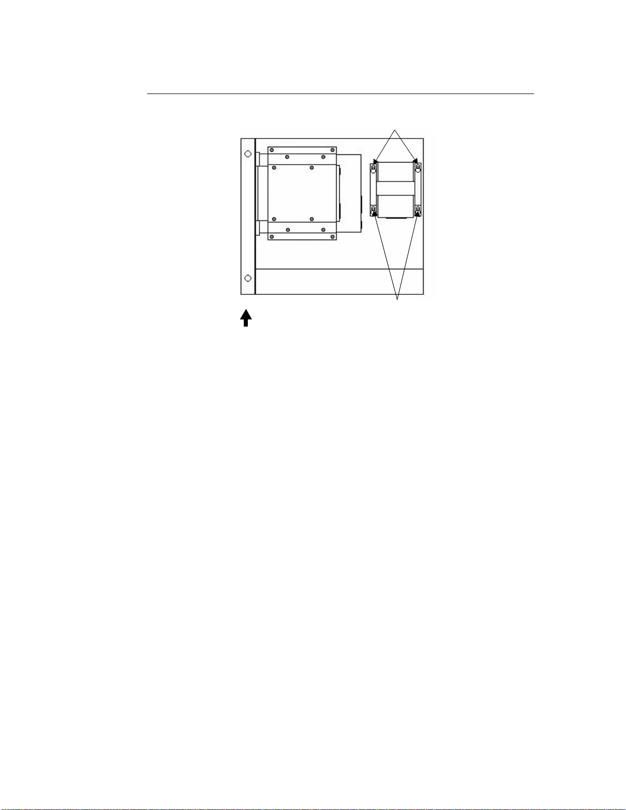
6. Insert, but do not tighten, the four retaining screws in the space
provided for the hard drive in the upper right side of the service
compartment. These screws will be provided in your Hard Drive
Replacement/Upgrade Kit.
Installing the Hard Drive
To install a new hard drive, follow these steps:
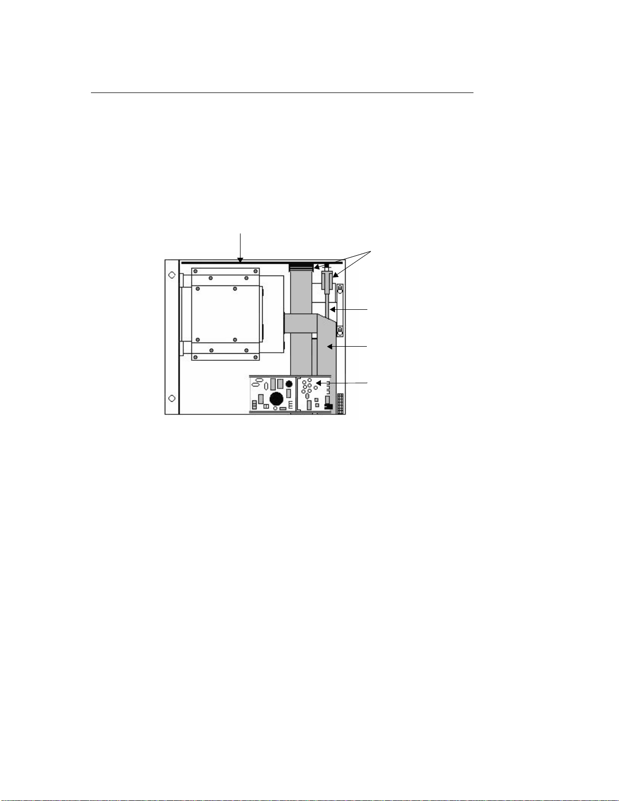
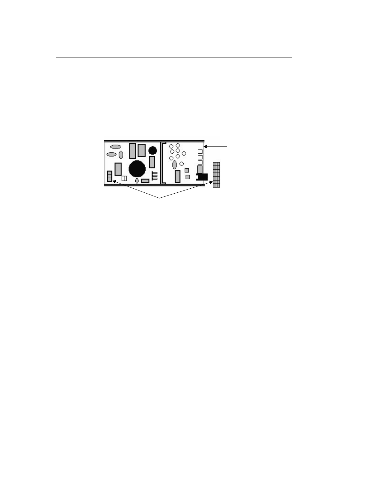
1. Attach the ribbon cable to the bottom of the hard drive.
• If this is a first-time installation, this cable will be included in
your Hard Drive Replacement/Upgrade Kit.
Note The cable end that you should attach to the hard drive has a
gray-colored key in the lower row of receptacles.
• If you are replacing a previouslyinstalled hard drive, re-attach
the cable that you removed in step 5 on page 5.
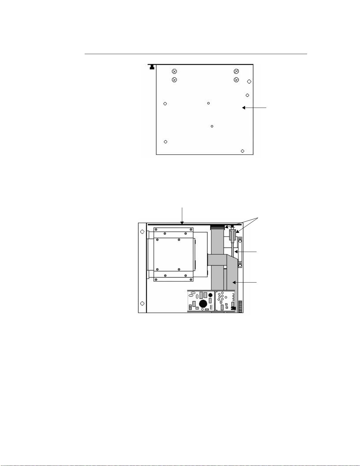
2. Place the new hard drive assembly over the four hard drive retain-
ing screws, and slide the assembly downward so that the screw-
heads fit over the small ends of the “keyhole” openings in the
bracket.
3. Tighten the four retaining screws.
4. If this is a first-time installation, fasten the free end of the ribbon
cable to its connector on the riser card.
This connector is directly below the bottom of the hard drive,
behind the cable connector for the CD-ROM drive.
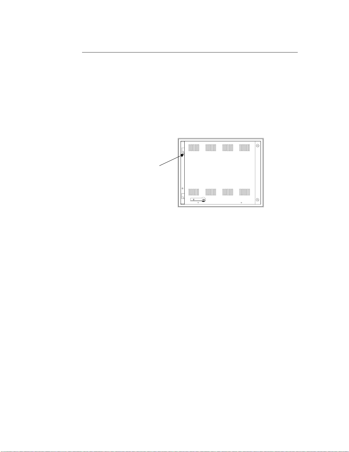
5. If necessary, re-attach the CD-ROM drive cable to its connector
on the riser card.
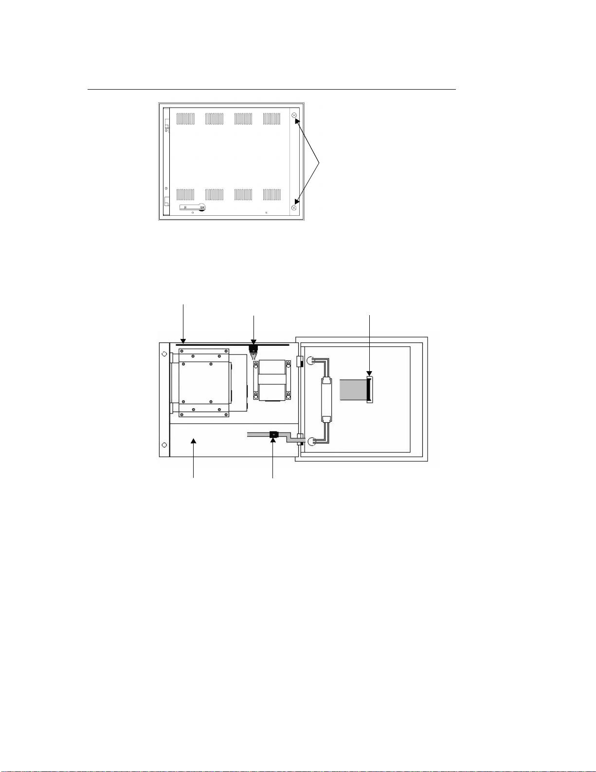
6. Re-attach to the monitor card the video and power cables that you
removed in step 2 on page 4, or in step 5 on page 7.
7. If you have removed the power supply from the unit, replace it by
following these steps:
a. Place the backshell on its back.
b. Replace the power supply in the unit, aligning the screw holes
in the bottom of the power supply with those in the bottom of
the unit.

PC9/P9 Hard Drive Installation
CTC Parker Automation
9
c. Replace the four screws that secure the power supply in place
and that you removed in step 4 on page 6. Be sure to replace
the nuts with screws 1 and 2.
d. Re-attach the two sets of cables that you disconnected from
the power supply in step 2 on page 6.
e. Turn the backshell upright.
Reassembling the Unit
To reassemble the unit, follow these steps:
1. Replace the backshell on its hinges.
Warning When lifting the backshell, grasp it from the outside. Be careful
not to touch the monitor card, locatedinsidethe top of the main-
tenance compartment.
2. Re-attach themonitor data cable, touchscreen cable(if necessary),
and backlight cable that you disconnected in step 6 on page 2.
(Press the monitor cable into its socket until the locking clamps on
either side of the connector snap into place).
3. Replace the safety bracket that you removed in step 7 on page 3,
and fasten it in place with its retaining screw.
4. Close the backshell against the faceplate assembly.
5. Fasten the backshell to the unit by replacing the two screws that
you removed in step 4 on page 1.
6. Reconnect power and other cables to the unit.
7. Reconnect the unit to the power source.
Your hard drive installation or replacement is complete. You may now
restart the unit.

PC9/P9 Hard Drive Installation
10
CTC Parker Automation
Other manuals for PC9
7
This manual suits for next models
1
Table of contents