Guarde este folleto para consultarlo en el futuro
CTC garantiza los accesorios para termostatos CTC contra
defectos en material o mano de obra por un periodo de tres
años a partir de la fecha de venta al usuario original o
compra por el consumidor. CTC reemplazara su accesorio
para termostato, si es que su accesorio para termostato
CTC no trabaja o falla durante el periodo de garantía debido
a defecto en el material o mano de obra.
ESTA GARANTIA REEMPLAZA TODA OTRA GARANTIA EXPRESADA. LA DURACION DE
CUALQUIER GARANTIA IMPLICITA, PERO NO LIMITADA A, CUALQUIER GARANTIA
IMPLICITA DE MERCANTIBILIDAD O APTITUD PARA UN USO EN PARTICULAR, EN LO
QUE RESPETA A SU TERMOSTATO CTC ES LIMTADO AL PERIODO EXPRESADO EN LA
GARANTIA ARRIBA.
Esta garantía no es validad si su accesorio para termostato CTC no es
comprado y usado en los E.E.U.U. Esta garantía excluye y no cubre defectos,
mal funcionamiento o fallas de su accesorio para termostato CTC si están
fueron causadas por reparaciones hechas por personas no autorizadas por
nosotros, mal uso, instalación inapropiada, modificaciones o daño a sus
accesorios para termostato CTC mientras en su posesión, o uso no razonable,
incluyendo no darle mantenimiento razonable y necesario.
CTC
Climate Technology Corporation
A Division of SUPCO, Inc.
P.O. Box 21
2230 Landmark Place
Allenwood, NJ 08736 USA
Soporte Técnico: 800-676-7861
www.supco.com
6390-100-01
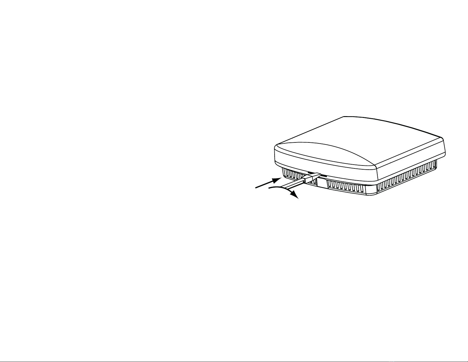
INSTALACIÓN cont.
NOTA:
Para controlar la temperatura, cuando el sensor remoto interior
está conectado al termostato, usted tiene que seleccionar el control entre
el termostato, el sensor remoto interior, o combinación de ambos
.
Consulte la Guía de instalación.
ª$MJNBUF5FDIOPMPHZ$PSQPSBUJPOt)FDIPFO$IJOB