manuals.online logo
Brands
  1. Home
  2. •
  3. Brands
  4. •
  5. CTD
  6. •
  7. Industrial Equipment
  8. •
  9. CTD CTD 200R Series User manual

CTD CTD 200R Series User manual

INSTRUCTION BULLETIN
& MAINTENANCE MANUAL
FOR CTD 200R SERIES
MODELS M25R, F255R,
F255RHC, M25RHC & CM325R
05.2016
CTD MACHINES
2382 E 48th Street
Vernon, CA 90058
Tel (213) 689-4455 • FAX (213) 689-1255
World Wide Web: http://www.ctdsaw.com
e-mail: ctdsaw@ctdsaw.com
CTD MODEL NO:
CTD SERIAL NO:
MANUFACTURE DATE:
DISTRIBUTOR PURCHASED THROUGH:
(IF ANY)
SUBJECT PAGE NO.
Machine Requirements............................................................................................................... 2
Installation and Set-Up................................................................................................................ 3
Electrical Installation.................................................................................................................. 6,7
Safety Instructions..................................................................................................................... 7
How to Operate the Machine..................................................................................................... 8
Air Pneumatics.......................................................................................................................... 12
Preventative Maintenance.......................................................................................................... 15
Repair and Service.................................................................................................................... 15
CM325 Special Set-Up............................................................................................................... 16
Spindle and Pivot Shaft Diagrams...............................................................................................18
200S Rt. Saw Exploded View ....................................................................................................19
200S Rt. Blade Guard Exploded View.......................................................................................... 20, 21
M25R Base Exploded View........................................................................................................22
F255R Base and Floor Stand Exploded View............................................................................... 23
Air Feed System Exploded View................................................................................................. 24
CM325R Lt. Saw Exploded View............................................................................................... 25
CM325R Lt. Blade Guard Exploded View................................................................................... 26
CM325R Lt. Base Exploded View............................................................................................... 27
M25HC Base Exploded View...................................................................................................... 28
200HC Series Blade Guard Exploded View.................................................................................. 29
Additional Parts......................................................................................................................... 30
Machine Requirements:
Cutting Capacities
Models M25R & F255R Model CM325R
M25R/45°Mitre: Maximum Cutting Capacity 90°Straight Cut:
12” Blade Capacity (305mm) 2-1/2” (63mm) High x 7” (178mm) Wide
2-1/2” (64mm) High x 4-1/4” (108mm) Wide 4” (101mm) High x 4” (101mm) Wide
3-1/2” (89mm) High x 4” (101mm) Wide 45°Mitre:
3-1/4” (82mm) High x 5” (127mm) Wide
Cutting Capacity with fences set at centerline: 3-1/2” (89mm) High x 3-1/2’ (89mm) Wide
45
°
Mitre: 2-1/2”(64mm) High x 3-1/2”(89mm) Wide 90°Front to Back/45°Compound:
90°Cutting: 2-1/2”(64mm) High x 5”(127mm) Wide 1-1/2” (38mm) High x 5-1/2” (140mm) Wide
1” (25mm) High x 7” (178mm) Wide
M25R & F255R/90°Cutting:
12” Blade Capacity (305mm)
2-1/2” (64mm) High x 7-1/2” (191mm)
3-3/4” (95mm) High x 3-3/4” (95mm) Wide
Electrical Requirements: Based on one motor per machine
-2-
Models M25RHC & F255RHC
14” Blade Capacity (356mm)
M25RHC/45°Mitre: Maximum Cutting Capacity
5” (44mm) High x 7.5” (190mm) Wide
M25RHC & F255RHC/90°Max Cutting:
5” (44mm) High x 9” (229mm)
Cutting Capacity with fences set at centerline:
45
°
Mitre: 5”(44mm) High x 5”(127mm) Wide
90°Cutting: 5”(44mm) High x 6.625”(168mm) Wide
Motor Size Req. Amperage Breaker Needed Motor Size Req. Amperage Breaker Needed
2 H.P 3Ph 208V 5.7 amp 20 amp 2 H.P 3Ph 460V 2.7 amp 20 amp
2 H.P 1Ph 230V 12.6 amp 25 amp 3 H.P 3Ph 230V 7.4 amp 20 amp
2 H.P 3Ph 230V 5.4 amp 20 amp 3 H.P 3Ph 460V 3.7 amp 20 amp
Installation and Set Up:
The CTD saw you have purchased is designed to cut wood, aluminum, plastic and steel, with, of course, the
proper blade and conditions. For the material you are cutting, please refer to the cutting instructions for each
material type. The 200R Series machines use a NEMA 56 Frame 2 H.P., 3450 RPM, 60 Hertz TEFC Motor.
CTD uses a speed-up so that the blade will run at approximately 11,000 SFPM on a 12” blade.
IMPORTANT: Before operating saw, please be sure to read the “SAFETY INSTRUCTIONS TO THE
OPERATOR” (see Page No. 7).
Note: The floor stand must be shimmed, leveled and bolted to the floor, or framed in to eliminate vibration.
Use holes provided in bottom of floor stand. All machines have been completely assembled at the factory,
then disassembled for shipment.
Assembly of Floor Stand, Support Tables and Measuring Gages:
Standard Machine—The standard model has been completely assembled. Fences are set at the centerline
of the blade (see Diagram “D” on Page No. 5). Adjust fences forward if necessary for your particular material.
The machine base must be level. The incoming material and outgoing material must lay flat on the machine
base (see Diagram “F” on Page No. 10).
Floor Stand Model—The 200R and 300R Series base is attached to the Floor Stand by means of three hex cap
screws bolted from the bottom of the base. The Floor Stand must be shimmed and leveled, and, if necessary,
bolted to the floor to eliminate vibration. The F255R is attached with (2) socket cap screws from the top in front,
and (1) hex cap screw from the bottom in the rear.
Space Requirements
-3-
Pneumatic Requirements: (if applicable) 1 CFM per 10 strokes at 75 PSI (.043 cubic meters at 5.4 kg/cm2)
Dust Collection Requirements: 800 CFM at 2” outlets
Cutting Tool Requirements: Wide, heavy, rigid plate 12” blades: .100 to .110 plate
-4-
Diagram “A”
Assembly of Tables to Floor Stand:
1. Assemble leg to table with 3/8-16 bolts and nuts provided. Turn table upside down and attach leg to table
with leg rising vertically. Note: The hole in the table (when mounted properly) should be toward the back
of the table and at the far end from the blade to attach Fence Support Angle, P/N BF16 (see Diagram “A”).
2. Attach Table, P/N BF17 to machine floor stand on Angle Bracket, P/N BF05C. Use 3/8-16 bolts and
nuts provided on angle bracket.
Blade Installation:
Before setting blades on spindle, always shut off or disconnect air supply. With Motor OFF and Power
Disconnected, rotate Lower Blade Guard (p/n 200A270) up into Main Blade Guard (p/n 200A26L or R). Slide
link puller (p/n 200M320) off puller screw and bushing through large hole on slot. Remove four machine nuts on
Blade Guard Cover (200F250L or R). The entire Lower Blade Guard Cover Assembly (p/n 200E250L or R)
comes off as one piece, exposing spindle nut and flange. (Refer to Diagram “D” on Page No. 5.).
Attaching Extended Fence Gage:
1. Place Extended Fence Gage (5/8 x 2” material) on table. Bolt to fence bracket with screws provided.
Adjust fence gage so measurement rule is correctly set:
A. With a scale or ruler touching the side of the tips of the blade, measure a distance away from blade.
Be sure the ruler and the tape on the fence gage read the same. This may be visually deceiving. Use
a 90° square to check.
B. Adjust fence, left to right, as necessary.
C. Both fences, left and right, must be in perfect alignment. Use a long straight edge for this purpose
(see Diagram “D” & “E”).
D. Attach fence support angle to fence and table.
Diagram “B”
BF225 12’
Blade Installation (continued):
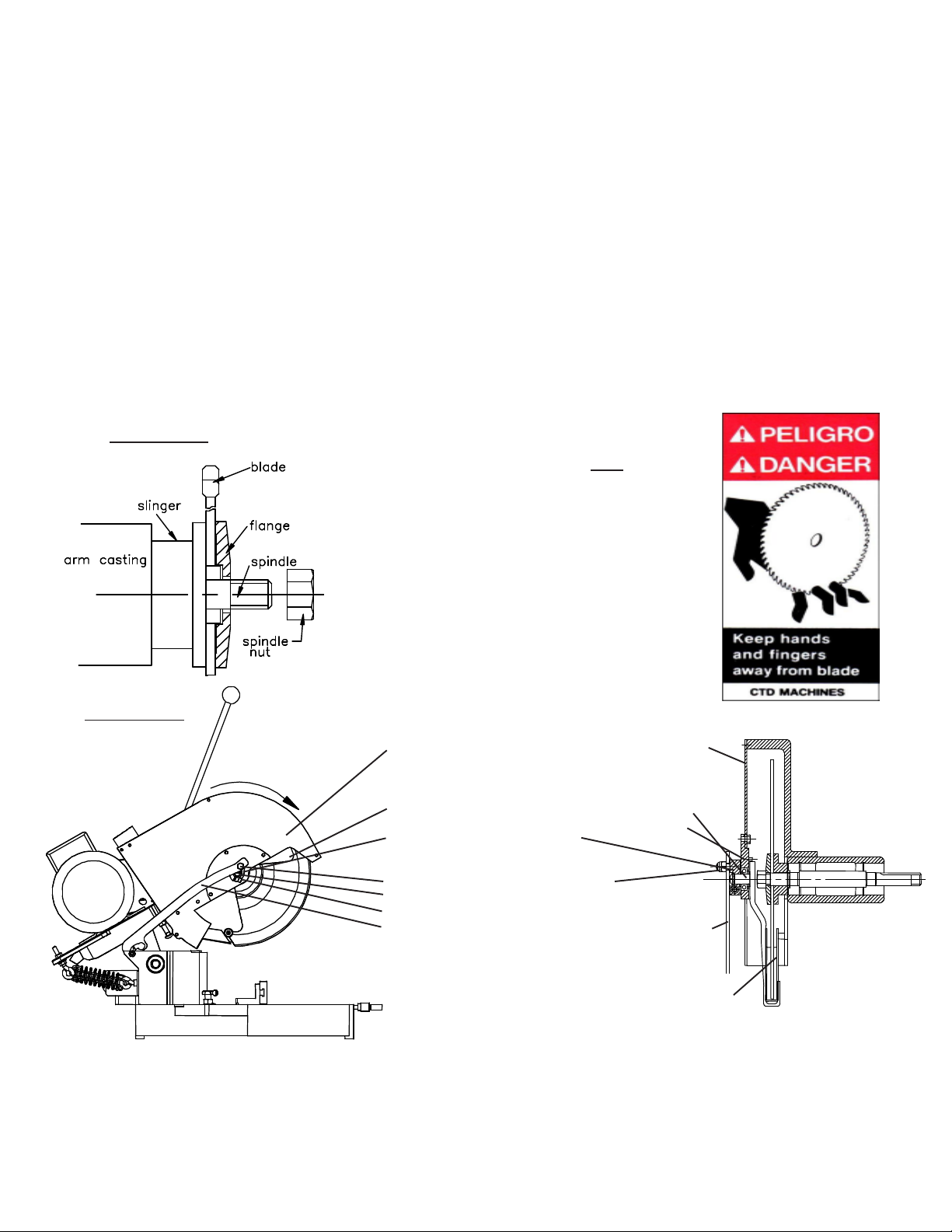
1. Remove Spindle Nut, P/N 2B1P36 or 2B1P37 and Outer Flange, P/N 200BM03. If necessary, hold blade
in hand with rag or lower blade into a piece of wood, and loosen spindle nut by pushing down on a 15/16”
wrench.
2. Place blade on spindle with tips pointing down. Make sure Slinger (inner flange), P/N 200BM04, and
blade surface are clean before putting blade on spindle. This is a critical surface and is ground within
.0005 flatness. Any debris or dust will wear this surface. Wipe both surfaces (blade and slinger) with
a clean rag.
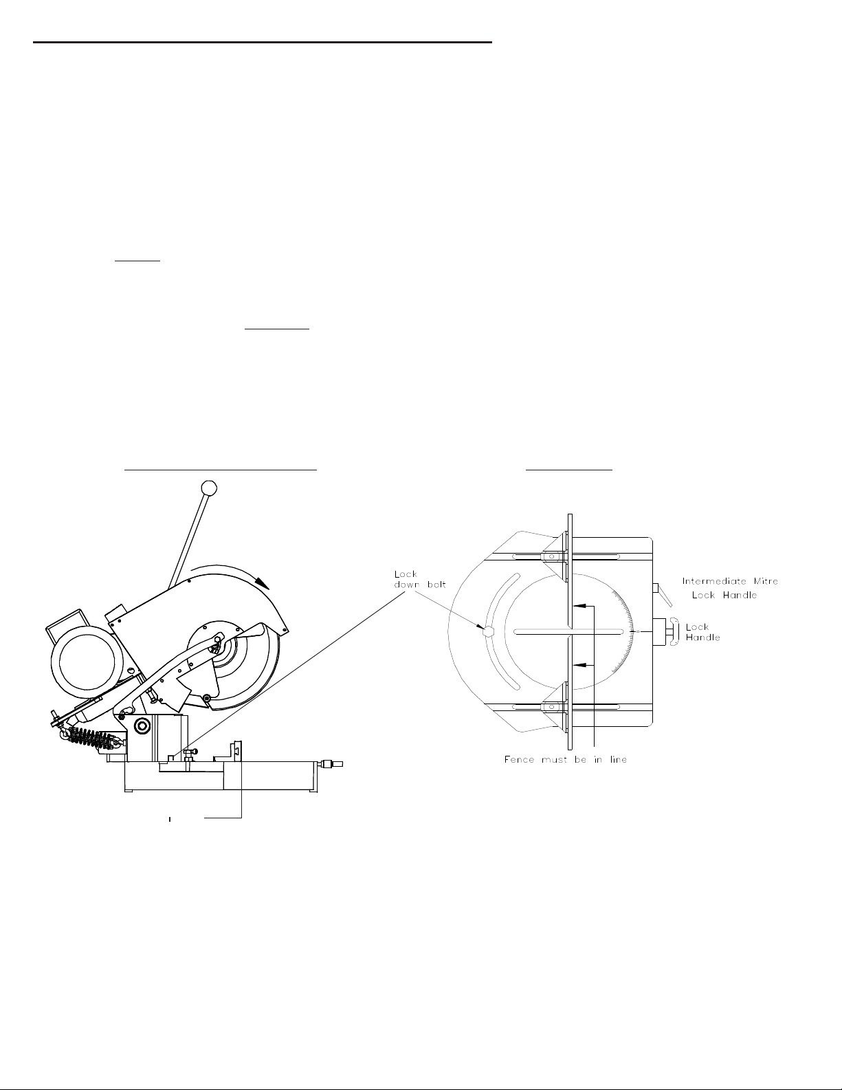
A. The blade must ALWAYS rotate to the rear of the machine on the underside of the blade
(see Diagram “D”). Always check rotation before cutting a piece of material.
3. Replace Outer Flange, P/N 200BM03 and nut as before and tighten (refer to Diagram “C”). Pull up with
15/16” wrench. Do not over-tighten. Snugging the blade is all that is necessary.
4. Replace Blade Guard Cover Assembly as before making sure Lower Blade Guard covers blade.
If blades were purchased from CTD, your machine has been set with your blades. If not, blade diameters may
vary. Check to see if the blade contacts the base or disc in the down position. If repositioning is necessary,
adjust down stop bolt located under Arm casting, P/N 200BC01L or R.
These machines are general purpose in
their design, therefore the user should
attach any additional guarding to the
blade guard or table base if the cutting
application causes unsafe blade exposure.
This label is attached to the blade guard.
Never put hand or fingers near or
under the moving blade.Use a piece
of wood to remove short pieces from saw.
Blade Guard:
The blade and belt drive are enclosed. When the saw arm is lowered, the lower blade guard rotates up into the
main blade guard. The blade continues through the work as the lower blade guard rotates up.
NEVER remove any blade guard part, exposing the blade.
-5-
Diagram “C”
1. 200F250R/L 12" N.S. Blade Guard Cover-200 Series
300F250R/L 12" Cover- CM325R
2. 200A26R/L 12" Main Blade Guard, Rt. Or Lt. – 200Series
300A26R/L Main Blade Guard – CM325R
3. 200A270 Lower Rotating Blade Guard- ½” pin
4. 200M265R/L Bearing Housing Blade Guard Assy.
5. 200M261 Rotating Pawl
6. 2B2P09 Rotation Bearing for Housing
7. 2BM13 Spacer Washers (3) for Pin
8. 200B1P267 Shoulder Bolt Pawl
9. 200B1P268 External Tooth Lock Washer
10. 200B1P269 Teflon Spacer Washer (outside)
11. 200M320 N.S. Blade Guard Link/Puller-200 Series
300M32 Link Puller- CM325R
12. 200B7P35 Rear Bushing for Link/Puller
13. 200B7P36 Front Bushing for Link/Puller
13. 200B2P30 Roller Bearing Lower Blade Guard
15. 200M36R/L Rear Blade Guard Channel Rt. or Lt.-200 Series
300M36R/L Rear Channel Rt. or Lt.- CM325R
16. 200M35 Top Dust Tube Main Blade Guard- 200 Series & CM325R
300M35 Rear Dust Tube Connector – CM325R
300A12 Rear Dust Outlet 4" CM325R
Parts for Blade Guard Assembly-See exploded views on pages 20 & 21
Diagram “D”
Blade rotation
Motor Load Amperes
Motor Size 110 Volt 220 Volt 440 Volt
2 H.P. 1 Phase
2 H.P. 3 Phase
3 H.P. 3 Phase
-6-
Electrical Installation:
The CTD 200R Series Cut-Off Saws use 2 H.P. single or three phase 3450 RPM, 60 HZ TEFC (totally enclosed fan
cooled) motors on a NEMA 56Z Frame. CTD uses a speed up drive so that the blade will run at approximately 3700
RPM. The motor is turned “ON” and “OFF” using the manual overload starter located on the top of the motor.
Electrical installation should be performed by a qualified and certified electrician. It is highly recommended
that a lock-out or disconnect switch be located close to the machine between your main electrical panel and
the machine. This disconnect switch is used to shut off power to the machine and should be used whenever
the blades are changed, or at any time the machine is serviced and the blade is exposed. A manual overload starter has
been provided as a standard feature. The starter protects the motor from overheating and will not allow the motor to restart
itself after power outages or undervoltage situations. A Magnetic Starter is also available as an optional accessory.
Electrical Installation of Power to Starter by a Qualified Electrician:
All wiring from the motor to the starter has been completed and tested at the factory several times.
The voltage has been clearly tagged. DO NOT CONNECTANY VOLTAGE THATIS DIFFERENT THAN
THE TAGGED VOLTAGE, AS THIS MAY CAUSE SEVERE DAMAGE AND DANGER. Consult the factory
if any changes are needed.
Bring power lines to the top of the Manual Overload Starter or Magnetic Starter. Use dust proof connectors if available.
Single Phase Motors:
Connect leads to L1 (line 1) and L2 for single phase motors. (See Wiring Diagram for Single Phase Motors
below.) Green ground wire must be grounded to enclosure. If using type “SO” wire and plug, use a romex
connector through starter box and a grounded plug. Be sure to check rotation. The blade must rotate down
and to the rear on the underside of the blade (see Diagram “D” on Page No. 5). If a change in rotation is necessary, switch
the #8 and #5 wires in the electrical box on the motor. Rotation is set at factory for single phase motors.
Three Phase Motors:
Connect incoming power line leads to L1 (line 1), L2 and L3. (See Wiring Diagram for Three Phase Motors
below). Green ground wire must be grounded to enclosure. Be sure tocheck rotation as polarities may be
different. The blade must rotate down and to the rear on the underside of the blade (see Diagram “D” on
Page No. 5).
If a change in rotation is necessary, reverse any two of the incoming power wires. Example: Ifthe blades
are running backwards and incoming wires are connected White L1, Black L2, Red L3, switch the Black
wire with the Red so that Black is connected to L3 and Red is connected to L2. This will change the motor
to rotate properly.
JUMPER
JUMPER
FROM LINE
TO MOTOR
SINGLE-PHASE WIRING
JUMPER
FROM LINE
TO MOTOR
MANUAL OVERLOAD STARTER
THREE-PHASE WIRING
25 amps
N/A
N/A
12.6 amps
5.4 amp
7.4 amp
N/A
2.7 amps
3.7 amps
Safety Instructions to the Operator:
1. KNOW YOUR CTD SAW. Read this instruction manual carefully. Learn the operation, application, and
limitations, as well as the specific potential hazards peculiar to this machine.
2. Avoid accidental starting. Make sure switch is OFF before plugging in power cord. A Magnetic Starter
is provided as an optional accessory to give the operator added protection. (OSHA required by user.)
3. Always use a plug equipped with a ground.
4. Always keep blade guard in place. Do not wire-up or chain-up, so that blade is exposed.
5. Be sure all unnecessary tools are removed from machine before turning on power.
6. Use safety goggles. Also use a face or dust mask if operation is dusty.
7. Support work. To maintain control of work at all times, it is necessary that material be level with
cutting surface.
8. Wear proper apparel. Do not wear loose clothing or jewelry. Do not wear a tie or gloves. These items
can get caught in the moving parts of the machine.
9. Do not over-reach. Keep your proper footing and balance at all time.
10. Maintain your machine in top condition. Use proper blades. Clean machine weekly for proper
maintenance.
11. Keep work area clean. Cluttered areas, benches and slippery floors invite accidents.
12. Avoid dangerous environments. Keep work area well illuminated.
13. Wear ear protection if exposed to long periods of very noisy shop operations.
14. Keep visitors away. All visitors should be kept a safe distance from work area.
15. Do not force the machine. The saw will do a better job and be safer to operate at the speed for which it
was designed. Forcing the saw can be very hazardous to the operator.
16. Use recommended accessories. Use of other accessories may be hazardous. Use this instruction manual
or consult CTD for the proper accessories available.
17. Do not drown the blade using a steady stream of coolant when cutting non-ferrous materials. Only spray
the work to cool it.
18. Be sure to use the proper blade for the particular material to be cut.
19. Disconnect power cord before adjusting, servicing, and before changing belts, or for installing
accessories.
20. Safety is a combination of operator COMMON SENSE and ALERTNESS at all times when the machine
is being used.
21. WARNING!!! DO NOT ALLOW FAMILIARITY (GAINED FROM FREQUENT USE OF YOUR
SAW) TO DULL YOUR AWARENESS!! ALWAYS REMEMBER THAT A CARELESS FRACTION OF
A SECOND IS SUFFICIENT TO INFLICT SEVERE INJURY!!
-7-
Wiring Diagrams
Positioning the Work:
Fences should be set so that the centerline of the work is either to the front, or on the centerline of the blade
(see Diagram “D”). Fences must be adjusted so that short pieces cannot be trapped between the blade and
the fences. The Fences are adjustable side to side to close the gap. Gap should be 1/16” to 1/8”. Fences must be in line
with each other—front to back (see Diagram “E”). If very short pieces are to be cut, a piece of wood or aluminum can be
fixed to the table to make a sub-table, which will stop pieces from being trapped between the blade and the saw slot
(see Diagram “G” on Page No. 10). New machines are provided with a Chip Breaker which eliminates the need for a
subtable.
-8-
Diagram “E”Diagram “D” Blade Rotation
1. Pull back spring loaded mitre locking pin & handle assembly & rotate to the right or left. This prevents the pin
from engaging. Mitre lock pin & handle will lock in the open position.
2. Make sure mitre lock down bolt (located in the center of the pivot bracket-see Diagram “D” & “E”) is loosened.
3. To lock in at preset angles, rotate sawhead and disc near the desired angle aligning with zero mark on base.
Blade Rotation
centerline of blade
in down position
Angle Adjustment on Model M25R:
To change the angle:
M25R BASE
How to operate the 200R Series Single Cut-Off Saws:
Before operating the machine, please read the “SAFETY INSTRUCTIONS TO THE OPERATOR” above.
Other important information and features need to be learned before operating the machine.
Rotation:
The blade must rotate to the rear of the machine on the underside of the blades (see Diagram “D” below).
Blade Guard:
The blade and belt drive are enclosed. When the saw arm is lowered, the lower blade guard rotates up into
the main blade guard. The blade continues through the work as the lower blade guard rotates up. NEVER
remove any blade guard part, exposing the blade. These machines are general purpose in their design,
therefore the USER should attach additional guarding to the blade guard or table base if his cutting application
causes unsafe blade exposure.
Hand Operated Machines and Cutting Speed:
The blade is rotating at approximately 3700 RPM. When moving the blade through the material, the blade must NEVER
be allowed to dwell in the work. If fine finishes are required:
1. Use a sharp blade. Do Not Force the Cutting Action, causing the motor to stall.
2. Use a constant, even pressure when cutting through material.
Spring Return:
Each sawhead is equipped with a drawbar return spring. The function of the spring is to return the sawhead to the
rest position upon release of the handle. Do not adjust the spring pressure. If the spring breaks, Replace It
Immediately! Make sure spring is attached properly (see Diagram “D” on Page No. 8) and Never use a hand
operated machine without the return spring in place.
Clamping and Work Slippage:
The work must never be allowed to move or vibrate as it is being cut. When the work is positioned against a stop,
it must be clamped either by hand holding or by pneumatic air clamps. Never allow unclamped work between
the blade and the stop, as the blade can grab the material and throw it, thereby causing damage to the
blade, the machine, and possibly harming the operator.
CTD offers both Horizontal and Vertical Clamps. The Horizontal Clamp pushes the material backwards against the
rear fence and is mounted in the keyways of the base. A Vertical Clamp holds the material down, against the table base, and
is mounted through and on top of the fence bracket. Both clamps are offered as optional extras and are highly recommended.
If you purchased your machine with an Air Downfeed of the saw, the clamps are actuated prior to activating saw head by
depressing the Foot Valve. An Anti-Tie Down, Two Hand Control drives down the sawhead. If clamps are purchased using
a hand operated machine, then the clamps will move into position by pulling the saw head down slightly. This releases the
Automatic Valve (AV) to supply air to the clamps. Be careful not to overtighten clamp cylinder bracket on the
cylinder. This will cause irregular function of the cylinder.
200R Vertical Clamp Assembly 200R Horizontal Clamp Assembly
-9-
1/4” elbow fitting
B3P61
shut off
valve
200M22
vert. cyl.
brkt.
2B3P20
3” stroke
air cyl.
2B3P20C
vert. clamp
pad
200BIP22
wing nut
VC
1/4” red polyflo line
200B7P19
adjustable
lock handle
200M21
vert. clamp
adjustment
brkt.
200M20B
horiz. bar adj.
for vert. clamp
200M20C
vert. clamp
support bar
2BM28
horiz. clamp
pad
200B3P21
3” stroke
air cyl. 200M27
horiz. clamp
key
B3P61
shut off
valve
1/4” elbow fitting
1/4” red polyflo line
200B7P19
adjustable
lock handle
200M22
vert. cyl.
brkt.
4. Turn mitre locking handle to center position, and the spring loaded pin & handle will automatically engage into
preset angle settings. The preset angle settings are 45°, 30°, 22 ½°, 15°, 0° on both sides of the centerline or zero
point. Do not let the spring loaded mitre locking pin & handle engage in several degree settings as
you rotate the mitre base disc. This will cause excess wear on preset angle settings.
5. For all angles that are not preset, follow instructions under #1 to lock handle in the open position.
Simply align degree quadrant on disc with zero mark on base and tighten down intermediate mitre lock handle
located in base.
Removing Material From the Blade:
If the machine is stalled while cutting, immediately shut saw off and disconnect power. NEVER attempt to
free the bladewhile the motor is stillon. If a piece is bound on the blade, do not attempt to raise the blade
out of the material. Instead, tap the piece down on both sides of the blade with light pressure until the piece
has freed the blade.
Cutting the Material:
The material to be cut (both the incoming pieces and the cut pieces) must lay flat on the table base, or the
blade may bind the material. THIS CAN DAMAGE THE BLADE OR THROW THE CUT PIECE OUT
OF THE SAW, POSSIBLY HARMING THE OPERATOR (see Diagram “F”).
Diagram “G”Diagram “F”
Check your material for squareness using a 90 degree square. Material that is out of square will move when it is
cut, causing irregular mitres. (See “Irregular Mitres” on Page No. 16.) Additional tooling may be required.
Consult factory for more information.
Cutting Wood:
While wood is generally soft and simpler to cut than aluminum, it requires that the material be held in place
as the blade passes through the material. CTD suggests using a Carbide Blade with Alternate Top Bevel (AT)
for lighter wood sections and picture frame mouldings. This type of blade gives the finest of finishes. No
ONE blade will cut all materials perfectly. High lacquers or mica mouldings require a special modified blade
for best results. Consult factory. Never use a woodblade to cutaluminum, as it will chip and fracture the
carbide tips of the blade.
Cutting Aluminum:
As with cutting any material, it is important that aluminum be clamped properly. Precision blades are
required for accurate cutting. CTD suggests and uses a Triple Chip Grind on all its non-ferrous Carbide
Blades. When cutting aluminum, or other non-ferrous materials, it is essential that the blades be lubricated
with a Sawblade Lubrication System or other blade lubricating system for the finest finish. See “Sawblade Lubri-
cation System” or “CTD Biolubrication System” on Page No. 11 for more details.
Abrasive Cutting:
When abrasive cutting, cut at the fastest speed rate the motor will allow. Do not stall the motor. Blade will
glaze as a result of too slow a feed rate, or too hard a composition. Abrasive blades may break due to
movement of the work, twisting of the blades, or glazing of the cutting edge. Seldom do abrasive blades
break because of too fast a feed rate. The thinnest section of material should be presented to the blade.
For example, when cutting 1” x 2” stock, stand the piece up so the 1” edge is cut. Abrasive blades have
the tendency to wander when lengths of less than 1/2” are cut. The burr will normally be heaviest on the cut
piece. To eliminate this condition, the cut pieces should be clamped.
-10-
material must lay
flat on base and
work supports
never allow material to rest uneven
on base or work supports
blade
subplate to
support small
pieces
slot in table
work to saw
base
Sawblade Lubrication System:
The Sawblade Lubrication System is used when cutting aluminum or other non-ferrous materials. This system
normally uses a Water Soluble Oil mixture of 10 parts water to one part oil. The system operates by syphoning
the lubrication up the line to the spray nozzle. Any air leak will cause inconsistent fluid flow to the spray nozzle.
BE SURE your fluid is free from chips and other debris. A fluid container supplied with the machine contains
a One-Way Check Valve, Part No. B3P96, at the end of the clear fluid line. This check valve helps to hold the
lubrication in the line. However, after a couple of minutes, the lubrication or oil will back-flow into the container.
Priming of the system may be necessary if the machine has been standing without use. The system may be shut
off by closing the toggle valve next to the vacuum pump. The fluid must be clean or the Vacuum Pump will clog.
CTD Bio Lubrication System:
The CTD biodegradable lubrication system operates by pulse spraying a minute amount of biodegradable
lubricant directly on to the saw teeth of the blade in time-measured increments. The majority of the lubricant
then dissipates with the heat of the cutting action. Chips coming off the blade are hot and dry, and are more
easily collected. (See specific instructions included with system.)
-11-
Combination Blades:
Any combination blade is basically an aluminum cutting blade. Significant blade life in between sharpenings
will be lost if a blade is used for cutting both aluminum and wood. The amount of production for either wood
or aluminum should be the determining factor in the assessment of the particular blade type to be used.
Please consult factory.
Sound Levels:
During normal running of the machine without cutting, the typical sound range will be between 60-85 db.
Due to the wide variety of blades available, CTD cannot warrant that maximum allowable OSHA sound limits
can be met--particularly during the cutting cycle.
Cutting Plastic:
Plastic can be cut as easily as wood on the 200R Series Saws. However, because of its elastic properties, the material
can deflect as the blade passes through. Therefore, it is important to clamp the material as close as possible to the
blade and support it by use of fixtures. CTD offers Horizontal and Vertical clamps for this application (see Page No. 9)
Additional tooling may be required. Special carbide blades are avaialble for cutting plastics.
200R and 300R Series Air/Pneumatic System:
The air pneumatic system on the 200R Models and the CM325R is simple to use and understand, and easy
to operate. The main components of the air system are shown below in the Air Circuit Piping Diagram.
The system operates using a Two-Hand Anti-Tie Down Control for safety. Included with the Air Pneumatic
System are the main drive Cylinder and Valves, an Air Filter/Regulator, and one Vertical Pneumatic Clamp. The Vertical
Clamp is actuated prior to the activation of the saw head via a Foot Valve, P/N B3P53E, (recommended for safety) which
in turn energizes the Two-Hand Control. Note: Pressure must be maintained on the Foot Valve until Two-Hand activation.
The system will not allow unclamped material to be cut. The two hand buttons must be depressed at the same time for the
saw head to travel downwards. The system operates first by depressing the Foot Valve, P/N B3P53E. This gives a signal
to the Shuttle Valve, P/N B3P86, to allow air to pass to the Two Hand Anti-Tie Down Control, P/N B3P110. By de-
pressing both palm buttons simultaneously (at the same time), a signal is given to the main 4-Way Control Valve, P/N
B3P73 to change direction—allowing air to pass to the main drive Cylinder, P/N 2B3P05. The Cylinder pushes the saw
head down. The speed of descent is controlled by the Speed Control Valve, P/N 2B3P61, located on the Cylinder. By
releasing the Two-Hand palm buttons, air is shut off to the main 4-Way Valve, it shifts direction and the main drive cylinder
reverses.
-12-
Air Schematic
Air Circuit Piping Diagram
No. Part No. ** Description.
1 B3P110 2-Hand 2-Hand Anti-Tie Down Control Assembly
1 2B3P05 Air Cylinder, drive for saw head
1 2B3P61 Flow Control Valve, speed of saw down
1 B3P73 P1 4-Way Spring Return Valve, main control valve
1 B3P50 LV1 3-Way Normally Open (N/O) Valve, controls accessory items SLS and VC3
1 B3P63 Upstroke Valve, speed of saw up
1 2B7S15 Rubber Bumper
1 B3P154 FR Unit with Auto Drain
2 200M81 Cylinder Support Studs
2 200B2P80 Rod Ends / Air Feed
1 200M82 Cylinder Clevis
1 200M84 3 Way Valve Bracket
1 200M87 Power Feed Cylinder Support Bar
1 200M86A Rotating Cross Bar for Cylinder
1 B3P86 S1 Shuttle Valve
1 B3P51 FV 3-Way Normally Closed — Foot Valve
See Exploded view on page 24 and additional Parts on Page No. 28
**Refer to Air Schematic on Page No. 12
200R Air/Pneumatic System Diagram
B3P110
2-Hand Anti-Tie
Down, Maintained
Contact Unit
2B3P05
Air Cylinder
2B7S15
Rubber
Bumper
200M86A
Cross Bar
2B3P61
Down Stroke
Valve
B3P63
Upstroke / Speed
Control Valve
B3P73
4 - Way Spring
Return Valve
B3P86
Shuttle Valve B3P50
3 - Way N/O
Valve
200M81
Cyl. Supt. Rods
200B2P80
Rod Ends / Air Feed
-13-
Air Supply:
The air supply must be turned off and all electrics disconnected before making adjustments on the power feed.
A working pressure of 75 PSI (pounds per square inch at 5.4 kg/cm2) is required. An industrial-type compressor
of at least 3 CFM (cubic feet per minute) is recommended. An additional 3 CFM is required for Spray Mists.
A conveniently located valve should be supplied by the user to shut off the air line. Arms should be raised or
lowered by hand when setting up machine. The machine must use clean, filtered air. The speed of descent of
the saw head will vary if the air pressure varies. An Air Filter/Regulator/Lubricator is essential.
Air Cushion Bearing System:
The machine you have purchased comes with a built-in air cushion bearing system that works off your air supply. If you
have purchased an air/pneumatic system, then the air bearing will be charged when you add air to the machine.
If the machine you purchased is a manual machine, then the 1/4” blue air line at the back base of the machine must be
connected to at least 75lb PSI of air pressure for the bearings to work properly.
The operator should have the air switch in the “off” position when not changing the mitering angles. The air bearing is self
cleaning and self lubricating when used with the CTD air filter/regulator/lubricator. If the machine was bought without the
FRL, then every 2 months, 3 drops of light machine oil should be placed into the blue 1/4” inlet air line at the back of the
machine.
FR:
An Air Filter/Regulator is installed ahead of the air inlet to the machine. This system helps prevent foreign material from
entering the system. It also provides lubrication in the air supply which helps prevent valves and cylinders from sticking.
The FR is comprised of two different components.
1. The Air Filter Bowl is located on the left side and is provided with an automatic drain. This collects and
then releases foreign matter and condensation collected by the air filter.
2. The Pressure Regulator, which is located on top of the air filter, controls the amount of air pressure allowed
into the system. An operating pressure of 75 PSI @ 5.4 kg/cm2 is required. (This is set at the factory.)
-14-
Trouble Shooting the Pneumatic System for Downfeed of Saw Head:
If the Air Feed no longer has smooth action, check the Downstroke Control Valve, P/N 2B3P61. If there is no
Speed Control, replace with Part No. 2B3P61. If air is leaking from the bottom of the cylinder, replace Cylinder
with Part No. 2B3P05 (for 200R and CM325R).
4-Way Valve:
The 4-Way Valve is the main control, five port valve located on the Air Feed Unit. If the saw is sticking in the
up or down position, the spool located in the valve probably is not shifting from side to side as necessary. This
condition is caused by unclean air passing through the system. The internal parts become gummed up, and the
air pressure can no longer shift the spool. A broken spring in the valve is another common cause. A 4-Way Valve
Repair Kit, P/N B3P76, is available for the valve.
Air Filter/Regulator
Foot Valve:
The Foot Valve, P/N B3P53E actuates the clamps into position. Once the Foot Valve is depressed, the Two
Hand Anti-Tie Down Control is energized and ready to activate. As soon as the Two-Hand Control buttons
are depressed, your foot can be removed from the Foot Valve. The clamp pressure will be maintained by
Limit Valve #1, P/N B3P50.
Speed Control of Blade Movement:
The downstroke speed of the blades is controlled by the Speed Control Valve, P/N 2B3P61, located in the
upper port of the main drive Cylinder, P/N 2B3P05. Adjust as required for best finish. The Upstroke Control
Valve, P/N B3P63, is located in port No. 5 of the main control Valve, P/N B3P73. Simply loosen nut on
machine screw (10-32 thread) and adjust in to slow down, or out to speed up.
Preventative Maintenance:
The 200R Series machines and CM325R are relatively easy machines to operate and maintain.
Following is a weekly check list of General Maintenance items. The best preventative maintenance advice
is to CLEAN THE MACHINE DAILY, especially around the pivot points on the machine.
Lubrication and Adjustments of Bearings:
NO LUBRICATION OR ADJUSTMENTS ARE REQUIRED. All CTD cut-off saws are assembled using
sealed, prelubricated ball bearings. The spindle and pivot assembly are constructed using preloaded belleville
springs. These springs eliminate the need for adjustments of bearings and also greatly increase the life of
the bearings. All air cylinders are “lube for life”.
General Maintenance Weekly Check List:
Always disconnect electrical power and air supply.
1. Keep machine clean—especially around pivot bracket and pivot bearings.
2. Blow off and clean around the cylinder
3. Check Air Filter Bowl for water and condensation build up.
4. Remove any scrap pieces and dust build up from inside floor stand (if purchased).
5. Check monthly;
A. For excessive belt wear
B. Make sure motor pulley set screws are tight.
-15-
Repair and Service:
Always use CTD factory authorized replacement parts and consult factory before making any repairs or
adjustments which may be unclear.
Air Hold Down Clamps for the Material:
Both Horizontal or Vertical Air Clamps are available and can be purchased as an optional accessory. These
clamps pneumatically hold the material in place when the saw blades are cutting the material. If clamps are not purchased,
the operator MUSTHAND HOLD THE MATERIAL. The clamps are controlled by a 3-Way Valve mounted on the
bottom of the Power Feed Unit. When the machine is in the rest position, the Upstroke Stud contacts the 3-Way Valve,
LV1. As soon as the Foot Valve is tripped, the clamps move into position. A manual shut-off for the clamps is provided
should you not want to use the clamps for a particular material.
If adjustments of the 90° mitre settings are necessary, you will need a precision draftsman’s square. Check
the 45° mitre by placing the square against the left fence and then sliding it over to contact the plate of the Carbide
Blade. Touch the triangle against the steel plate of the blade—not against the tips. If an adjustment is necessary, please
consult the factory
Irregular Mitres:
Irregular mitre cuts are almost always caused by out-of square material. Check your material with a 90°
square and a straight edge. Material that has a high spot on the bottom will move, or roll forward as it is
being cut (even with pneumatic hold down clamps), thereby causing the blade to cut more on the inside
of the moulding than the outside. Another cause of irregular mitre cuts is too thin a blade plate thickness.
Blade plate thickness should be .100 to .110 on 12” blades. Blades will find the easiest avenue to cut
through material, and sometimes the blade plate will distort when cutting heavier sections. The drawing
is an example of a cut when blade plate is too thin for the material being cut.
Other Repairs:
See specific areas within the manual for additional information on repairs and maintenance.
Instructions for Model CM325R:
To Change Angle for Mitre:
1. To change angle on machine, locate lock down bolt and loosen with standard 3/4” box wrench.
2. Manually rotate top base to desired degree setting, aligning angle mark with zero block. 45° and 90° stops
are provided.
3. Tighten lock down bolt. If you desire to mitre beyond 45° to the right, then 45° stop must be removed.
To Compound CM325R Saw Head:
1. Locate compound lock bolt on compound angle plate.
Using a 3/4” Box Wrench (see Diagram “H”), loosen lock bolt.
2. Remove dowel pin from 90° position, located in pivot bracket.
3. Manually move saw head to desired compound degree setting
by aligning pointer on degree quadrant. There are positive pin stops
at 90° vertical, 22-1/2° and 45° compound. Tighten lock bolt.
-16-
Diagram “H”
Fence Alignment and 45° Angle Adjustment of Blades for M25R:
All machines are preset at the factory for perfect 90° and 45° mitre cuts. If any adjustments are necessary:
1. Check alignment of fences—left to right as shown in Diagram “E” on Page No. 8. Use a two foot steel scale
or quality precision straight edge and lay flat on table base. Butt edge against fence bracket and long mea-
suring gage (if purchased). Touch the outside corner of the straight edge. If one side of the straight edge
pulls away from the fence, then the long fence gage is not in alignment with the left Fence, P/N 200M09.
2. Loosen 3/8-16 lock nut on Left Fence Bracket, P/N 200C05, and Fence Support Angle, P/N BF16. Clean
all surfaces of dirt or dust, and re-assemble as before (see Diagrams “A” & “B” on Page No. 4).
3. Re-align right fence to left fence with your straight edge. Once you are sure both fences are in alignment,
you now have a reference point to check your 90° mitre.
200 Series and CM325R Spindle Assemblies and Bearing Installation Instructions:
For Models M25R, F255R, and CM325R (refer to sketch on following page).
It is suggested that replacement spindle assemblies be purchased from CTD before disassembling. Old
spindles can be returned for bearing replacement and slinger refacing for a nominal fee. The 200R Series
and CM325R spindle assemblies provide for a “slip-fit” between the outer races of the bearing and the
housing or arm casting, and a “press-fit” between the inner race and the spindle. Great care must be taken
with ball bearings or the life of the bearings will be reduced. To remove the spindle assembly:
A. Loosen motor and remove belts.
B. Remove Spindle Pulley Nut #9 by holding pulley or slinger. Loosen set screws in pulley.
C. Remove Pulley #8, Pulley Key #13, and Spindle Spacer #7 (200R Series only). Place Pulley Nut #9
back onto spindle to protect threads.
D. With a soft hammer or rubber mallet, gently drive spindle towards blade side. Take care to protect
pivot bearings by holding arm casting on blade side to overcome effects of hammer blows.
E. Remove Pulley Nut #9, again.
F. Spindle assembly, consisting of Spindle #1, Slinger #3, and Blade Bearing #4 will come out of housing.
Outside bearing will slip out of housing. If a replacement spindle assembly was purchased, go to
item “L”.
G. If bearing on the blade side must be replaced, an arbor press must be used to disassemble the bearing
and the slinger from the spindle. Great care must be used in disassembling, or the spindle will be scored
or stripped by the slinger. Before pressing apart, scribe a line on the face of the spindle and the slinger
so that they will be re-assembled in exactly the same position in relation to each other. Use an arbor
press or pulley puller.
H. Press off slinger and bearing from spindle.
I. Press new bearing on to spindle, making sure spindle is square to the bore.
J. Replace slinger, as above, making sure scored lines match.
K. The face of the slinger must be checked to make sure the face (next to the blade) is running true.
If it is not running true, it should be refaced. Slinger should indicate < .001. To reface:
1. Partially assemble pulley bearing on spindle.
2. Hold outer races of both bearings gently in a vise.
3. Use the side of a surface grinder wheel to dress the face of the slinger by rotating spindle in bearings
slowly against the direction of the grinding wheel.
L. Clean bearing hole and slip new spindle assembly into arm casting up to snap ring. From the opposite
side of the arm, make sure that belleville springs #6 are assembled in housing as shown in Diagram
on Page No.18.
M. To re-assemble spindle assembly, slide outside bearing #4 onto the spindle as far as it will go, being
careful that bearing goes into housing square.
N. Slide pulley onto shaft with pulley key and spacer (for 200R Series only--no spacer is required on the
Model CM325R.)
O. Hold slinger or spindle nut. Replace jam nut on spindle threads and slowly tighten pulley jam nut.
This will push bearing onto shaft. Tighten thoroughly.
P. Since motor was moved, the centerline of the motor shaft and spindle must be parallel. Both pulleys
must be in line or belts will not wear evenly. This should be checked by placing a straight edge across
both pulley grooves. Tighten motor.
Q. Belt tension is of critical importance. To obtain proper tension, press down on top of belts with
moderate amount of pressure. Belts should deflect approximately 1/4”.
R. Tighten set screw in both pulleys. To check assembly after tightening belts, apply pressure in the
direction of the blade on the pulley nut. A slight spring pressure should be felt. If spindle does not
spring back, the belts may be too tight.
-17-
No. Description 200R Part No. 200R SPINDLE ASSEMBLY
1 Spindle, Right Hand 2BM02R
Spindle, Left Hand 2BM02L
2 Flange 200BM03
3 Slinger 200BM04
4 Bearing (2 required) 2B2P05
5 Snap Rings (2 required) 2B2P06
6 Preload Belleville Springs (4 required) 2B2P07
7 Spindle Spacer 2BM05
8 Spindle Pulley 2B4P23
9 Pulley Jam Nut, Right 151P16R
Pulley Jam Nut, Left 151P16L
10 3V335 Drive Belt, (2 required) 2B4P25
11 200 Series Arm, Right 200BC01R
200 Series Arm, Left 200BC01L
12 Spindle Nut, Right Thread** 2B1P36
Spindle Nut, Left Thread** 2B1P37
13 Pulley Key 2BM23
14 Spindle Assembly, Left & Right 200BE21L&R (consists of Items No. 1 - 7,9 and 12 with precision
ground Slinger)
**Note: A Spindle Nut, Left thread is used on the
Right hand saw, facing it from the front.
Belt guard is on right side, blade guard is on left side.
No. Description Part No. CM325R SPINDLE ASSEMBLY
1Spindle, Right Hand 30BM02R
Spindle, Left Hand 30BM02L
2 Flange 30BM03
3 Slinger 30BM04
4 Inside Bearing 30B2P05
5 Snap Ring (2 required) 9B2P06
6 Belleville Spring (4 required) 9B2P05
7 Outside Bearing 9B2P04
8 Spindle Pulley 30B4P23
9 Pulley Jam Nut, Right 151P16R
Pulley Jam Nut, Left 151P16L
10 3VX425 Drive Belt (2 required) 30B4P25
11 CM325R Arm, Right 30C01R
CM325R Arm, Left 30C01L
12 Spindle Nut, Right 30B1P36R
Spindle Nut, Left 30B1P37L
13 Pulley Key 2BM23
14 Spindle Assembly 30BE12L&R (consists of Items No. 1 - 7,9 and 12 with precision
ground Slinger)
200R SERIES AND CM325R PIVOT SHAFT ASSEMBLY
Assemble preload springs back-to-back as shown.
Pivot Shaft Parts:
A. Pivot Shaft, P/N 3BM08
B. Pivot Bearing, P/N 2B2P05 (2 required)
C. Pivot Belleville Spring, P/N 3B2P10 (2 required)
D. Pivot Snap Ring, P/N 3B2P11 (2 required)
-18-

This manual suits for next models

5

Popular Industrial Equipment manuals by other brands

Rytan RY100 user manual

Rytan

Rytan RY100 user manual

Cumberland 4801-5405 installation manual

Cumberland

Cumberland 4801-5405 installation manual

Philadelphia Scientific HydroCart Max instructions

Philadelphia Scientific

Philadelphia Scientific HydroCart Max instructions

Hotronix Power Platen quick start guide

Hotronix

Hotronix Power Platen quick start guide

Storch Airless Duomax 9000 manual

Storch

Storch Airless Duomax 9000 manual

Toray NHPA Series instruction manual

Toray

Toray NHPA Series instruction manual

Allen-Bradley 1492-P installation instructions

Allen-Bradley

Allen-Bradley 1492-P installation instructions

Lamtec FMS 4 quick reference

Lamtec

Lamtec FMS 4 quick reference

MyBinding SealerSales KF-772DH instruction manual

MyBinding

MyBinding SealerSales KF-772DH instruction manual

Bercomac BERCO 700964 owner's manual

Bercomac

Bercomac BERCO 700964 owner's manual

VEAB VFL-E Series Installation,operation and maintenance instruction

VEAB

VEAB VFL-E Series Installation,operation and maintenance instruction

ASA Electronics DA VINCI ST Original instructions

ASA Electronics

ASA Electronics DA VINCI ST Original instructions

Triumph Adler 5057i manual

Triumph Adler

Triumph Adler 5057i manual

TopGears ITG 125 Operation and maintenance manual

TopGears

TopGears ITG 125 Operation and maintenance manual

Samson 1352 Parts and technical service guide

Samson

Samson 1352 Parts and technical service guide

Schmalz FXP Operating instructions manual

Schmalz

Schmalz FXP Operating instructions manual

Emerson 781 quick start guide

Emerson

Emerson 781 quick start guide

Siemens 8UD1 1 A Series operating instructions

Siemens

Siemens 8UD1 1 A Series operating instructions

manuals.online logo
manuals.online logoBrands
  • About & Mission
  • Contact us
  • Privacy Policy
  • Terms and Conditions

Copyright 2025 Manuals.Online. All Rights Reserved.