CTR CLT 1 User manual

1
CLT1 User Manual
Bedienungsanleitung/ Mode d’emploi/
Manual de Instrucciones/
Manuale utente/ Bruksanvisning

CTR S.r.l. - Via T. ed E. Manzini, 9 - 43126 PARMA
Tel. +39-0521.957611 - Fax. +39-0521.957677
Eng................ 1-11
Deu................ 12-21
Fra................ 22-31
Esp................ 32-41
Ita................ 42-51
Ru................. 52-61
Pol................ 62-71
Ned................ 72-81
INDEX

3
Table of contents
User manual 3
CLT1 set 4
General information and technical data 5
Description 6
Connection 7
Preparation and start-up 8
Preperations prior testing the vehicle 9
Connecting the battery 10
Prevent error codes with CLTSIM 10
Test procedure 11
Possible solenoid valve errors 11
User Manual
CLT1 – Test tool for externally controlled compressors
Dear Customers,
Thank you for making the decision to purchase the CLT1 from Adiator.
The CLT1 can be used for testing all clutchless, direct drive, externally controlled
compressors, all year round, no matter how low or high the ambient temperature is.
The CLT1 has been designed “by technicians for technicians.”
Technical Application
The CLT1 will provide a direct power supply to the electronic control valve on all
clutchless, direct drive, externally controlled A/C compressors without having to
connect to the vehicle’s electrical system. Its simple, easy-to-use format will greatly
save valuable A/C diagnostic time. The CLT1 allows you to expand your A/C
diagnostic skills.
English
3

4
CLT1 Set
CLT1
CONTAINS Art. No.
CLTHK
CLTUNI
CLT PWS
CLTVAG
CLTDEN
CLTSIM
CLT1 central unit for the control of
clutchless compressors.
This unit enables you to control
clutchless compressors from Denso,
Sanden and Zexel.
Hook with magnet clip.
Universal cable harness (2m) for
connecting to any kind of clutchless
compressor.
Power supply cable for connecting to
the vehicle battery. 12V power supply
is needed.
Connecting cable (2m) for Sanden
(PXExx) compressors for Audi,
Lamborghini, Seat, Skoda and
Volkswagen.
Connecting cable (2m) for Denso
(6SEU16: 7SEU16) compressors for
BMW, GM, Jaguar, Lexus, Porsche,
Land Rover, Mercedes, Rolls Royce
and Toyota.
Solenoid valve simulator to prevent
generation of error codes in the car
system.
DESCRIPTION

5
General Information and technical data
GENERAL INFORMATION
• Please read this user manual carefully to avoid mistakes during the test. It helps
you preserve the test unit and the compressor.
• The user/technician has to have A/C knowledge.
• Adiator is not responsible for damage due to incorrect use of unit.
TECHNICAL DATA
• Voltage supply: 11 to 15 Volt
•Usage temperature: -10°C to +40°C
•Storage temperature: -20°C to +50°C
•Power consumption max. 3A
•Drives the compressor from 3 to 100%
•Weight: approx. 600g.
15 VOLT
-10°C to +40°C
Do you have A/C knowledge?
English
6
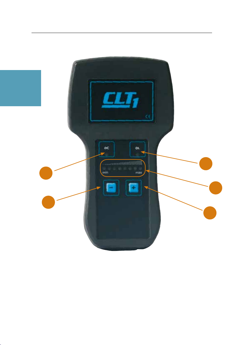
Description
1. Button to increase compressor capacity.
2. Button to decrease compressor capacity.
3. LED indicating short circuit or interruption of the electromagnetic valve.
4. LED indicating excess high power input of the electromagnetic valve.
5. 8 LED tachometer display for changing control valve capacity - / +.
3
2
1
5
4

7
Connection
1. Button to increase compressor capacity.
2. Button to decrease compressor capacity.
3. LED indicating short circuit or interruption of the electromagnetic valve.
4. LED indicating excess high power input of the electromagnetic valve.
5. 8 LED tachometer display for changing control valve capacity - / +.
1. 2-pin plug port for the
compressor control valve
harness.
2. 3-pin plug port for the vehicle
12V battery power supply.
1 2
English
8
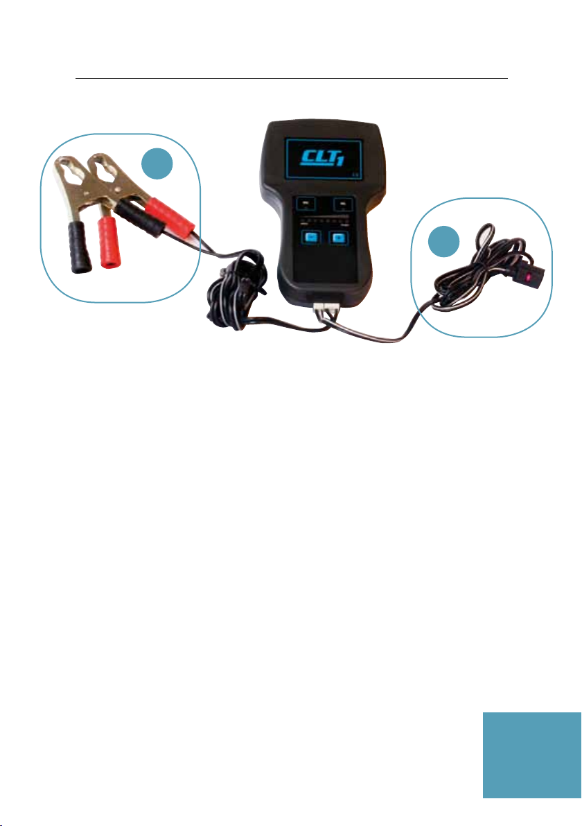
Preparation and start-up
1. Power supply harness for connecting the hand unit to the vehicle battery.
2. Compressor control valve harness. 3 options available for control valve
connector harness.
•Universal 2-pin Cable Harness, Pt No. CLTUNI,
connects to all compressors.
•VAG-Group Harness, Pt No. CLTVAG,
connects to VW Group.
•Denso Harness, Pt No. CLTDEN,
connects to BMW, Mercedes, Toyoto, etc.
1
2

9
1. Power supply harness for connecting the hand unit to the vehicle battery.
2. Compressor control valve harness. 3 options available for control valve
connector harness.
•Universal 2-pin Cable Harness, Pt No. CLTUNI,
connects to all compressors.
•VAG-Group Harness, Pt No. CLTVAG,
connects to VW Group.
•Denso Harness, Pt No. CLTDEN,
connects to BMW, Mercedes, Toyoto, etc.
Preparations prior testing the vehicle
• The vehicle should be at operating temperature.
•Set the air conditioning system to maximum cold.
•Set the speed of the blower on maximum.
•Only use vents in the centre of the car (close others).
•The airflow should be positioned and set at face vent level. Position a temperature
probe in the centre allowing you to measure the air outlet temperature.
•Connect a gauge or A/C service station to allow you to view the operating
low and high side system pressures.
•Disconnect the plug on the A/C compressor control valve or control valve harness.
Connect the appropriate CLT1 Universal, VAG-group or Denso harness.
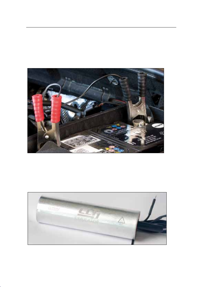
• Connect the simulator to the disconnected control valve plug.
Shows you an example of the CLT1 connected to a compressor.
General Advice
The 12V battery power supply should be maintained for the protection of the test
equipment and the compressor.
English
10
Connecting the battery
Attach the 12V battery clamps to the vehicle battery ensuring the correct polarity
connections; otherwise the CLT1 unit will be damaged.
This means:
Red = positive = plus = 30
Black = negative = ground = 31
Prevent error codes with CLTSIM
To prevent storing an error code in the vehicle’s electronic fault code memory system,
use the simulator (Pt No.: CLTSIM). Connect the simulator to the disconnected control
valve plug.
The CLTSIM has a universal 2-pin connector that will fit all vehicle control valve harness
applications. For vehicles with a single wire harness, connect one of the pin connectors
to ground 31.
Other manuals for CLT 1
1
Table of contents
Languages:
Other CTR Test Equipment manuals


