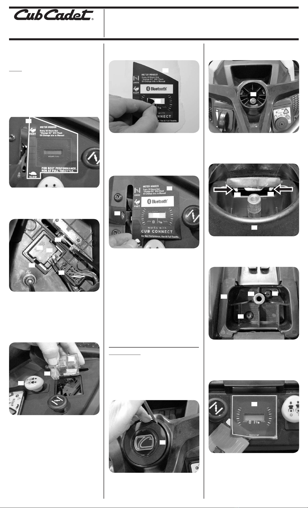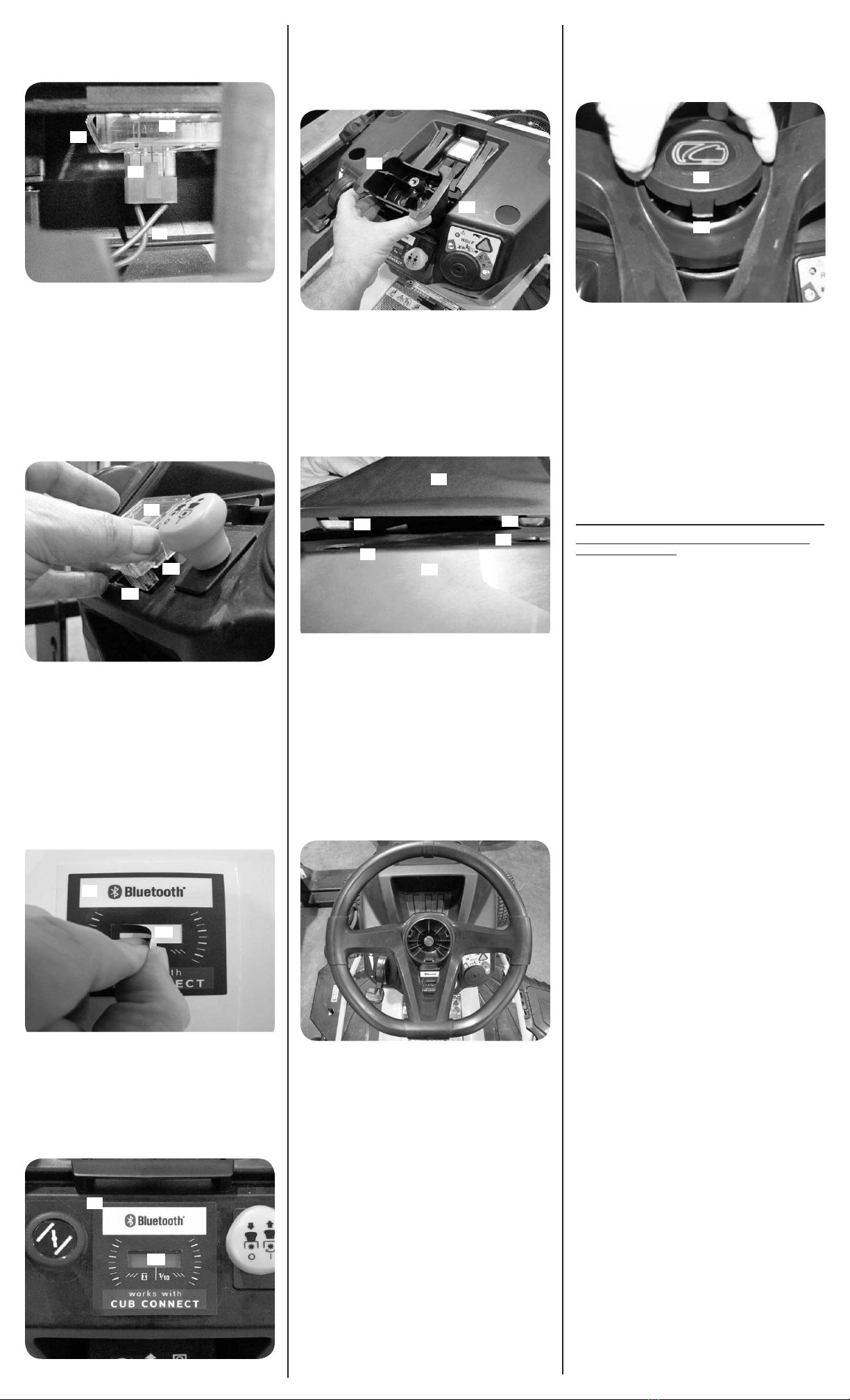
9. Reach up inside the dash and disconnect the
main wire harness (a) from the maintenace
meter (b). Press the tab (c) on the wire harness (a)
and pull down. See Figure 11.
Figure 11
10. Reach up inside the dash and squeeze the two
tabs (d) on the sides of the maintenance meter
(b) while pushing up and out of the upper
dash and discard the maintenance meter. See
Figure 11.
NOTE: A small flathead screwdrive may be used
to assist in the removal of the maintenance meter.
11. Make sure the surface of the dash is clean of
dirt, label residue, etc. Clean as needed.
12. Install the Bluetooth® Hour Meter (725-06221) (a)
into the opening as shown in Figure 12.
Figure 12
NOTE: The terminal block (b) must be at the
bottom of the opening as shown in Figure 12.
13. Push the Bluetooth® Hour Meter (a) all the way
into the upper dash until the two tabs (c) snap
into place. See Figure 12.
14. Install the wiring harness to the Bluetooth®
Hour Meter. Make sure the wire harness snaps
into place.
15. Remove the black rectangular section (a) from
the center of the RZT Maintenance Meter Label
(777I25406) (b) and discard. See Figure 13.
Figure 13
16. Install RZT Maintenance Meter Label
(777I25406) (a). Carefully align the label over the
maintenance meter so that the open rectangular
section is centered over the silver rectangular
LCD display (b) and parallel with the edge above
and below the RZT Maintenance Meter Label.
See Figure 14.
Figure 14
17. Make sure all the air bubbles are removed
from under the label.
18. Install the steering shaft bearing (a) over the
steering shaft. Lower into position until the
steering shaft bearing (a) contacts the upper
dash (b). See Figure 15.
Figure 15
19. Install the two shoulder screws removed in
Step 6 that secure the steering shaft bearing
to the steering bearing mounting bracket.
Tighten the shoulder screws to a torque of
68-85 in-lbs.
20. Install the dash cap (a). The dash cap (a) has
four tabs (b) that lock into four holes (c) in the
top of the upper dash (d). See Figure 16.
Figure 16
21. Set the dash cap (a) on top of the upper dash (d)
so that it just hangs over the back edge. This
positions the four tabs (b) of the dash cap (a) into
the four holes (c) of the upper dash (d) shown in
Figure 16.
22. While holding light pressure downward, push
the dash cap (a) towards the engine. This will
allow the four tabs (b) of the dash cap (a) to lock
into the four holes (C) of the upper dash (d). See
Figure 16.
23. Make sure the front wheels are facing straight
forward and position the steering wheel as
shown in Figure 17.
Figure 17
24. Install the screw removed in Step 4 to secure
the steering wheel to the steering shaft.
Torque the screw to 18-22 ft-lbs.
25. Install the steering wheel cap (a) into the
center of the steering wheel. The steering
wheel cap (a) has three locking tabs with one
being larger. The larger locking tab (b) is to be
at the 6 o’clock position when installing the
steering wheel. See Figure 18.
Figure 18
26. Close the hood.
27. Connect the positive and then the negative
battery cable.
28. Turn the key to the on position. The
Bluetooth® Hour Meter should display the
hours.
29. Start the rider and confirm the Bluetooth®
Hour Meter is functioning correctly.
NOTE: Connect the Bluetooth® Hour Meter to
your smartphone by downloading the Cub
Connect™ App for your Bluetooth® capable
Android or iOS device. See the Cub Connect™
Mobile App Bluetooth® Operation Device
Compatibility section for instructions.
Cub Connect™ Mobile App Bluetooth® Operation
Device Compatibility
Cub Connect™ is compatible with the following
devices:
• iPhone 4S/ 5 / 5S (iOS 6 or later)
• iPod Touch (iOS 6 or later and Bluetooth®
compatible)
• Android 4.3 (or later and Bluetooth®
compatible)
Smart Hour Meter
The hour meter “advertises” the hours run and the
battery voltage via a Bluetooth® antenna. There is
only one way communication, meaning the hour
meter will talk to the Bluetooth® app only.
Setup Conditions
When setting up the Cub Connect™ App, it is
important to make sure the phone power is on and
the Bluetooth® setting is on. The key should be in the
“on” position and the phone and equipment should
be within 150 ft. of each other. It is important to
remember to turn off the ignition when done using
Cub Connect™.
Finishing Setup
To finish the setup, you must enter the model and
serial number of your unit. You will need to manually
enter the 11-digit factory number from the ID tag
and you can scan the bar code from the ID tag for
the serial number. Once this is done just click on the
continue button.
Navigation Menu
There are 6 navigation options that you can choose
from in the navigation menu:
• Dashboard – Lists numerous maintenance
items you can check
• Maintenance Records – Lists all maintenance
that has been done to the unit.
• Operator’s Manual
• Service Centers
• Product Registration
• Customer Service
Operator’s Manual
When you pull up the Operator’s Manual, you must
accept the disclaimer as you would when you pull it
up online and you only have to accept it once. The
manual does open up in a PDF format.
Find a Service Center
Finding a Service Center is the same as using the
Dealer locator. Enter your zip code and the mileage
range you want and the results will show in a map
view or you can select a list view. You can also get
directions and the phone number for the dealer.
Product Registration
You can register your unit right from the Cub
Connect™ app. Product registration is listed as an
option in the Navigation Menu. You must fill out
the required information and click on the complete
process button. It will return to the dashboard and
the Product Registration should no longer be visible.