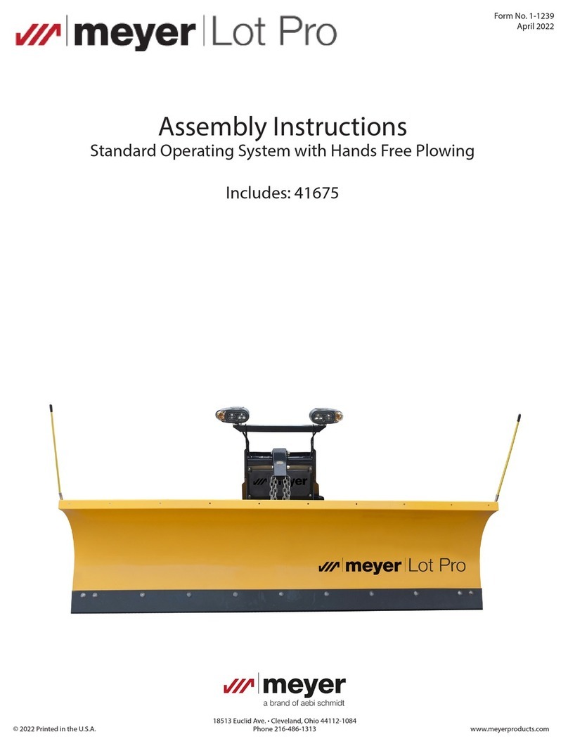
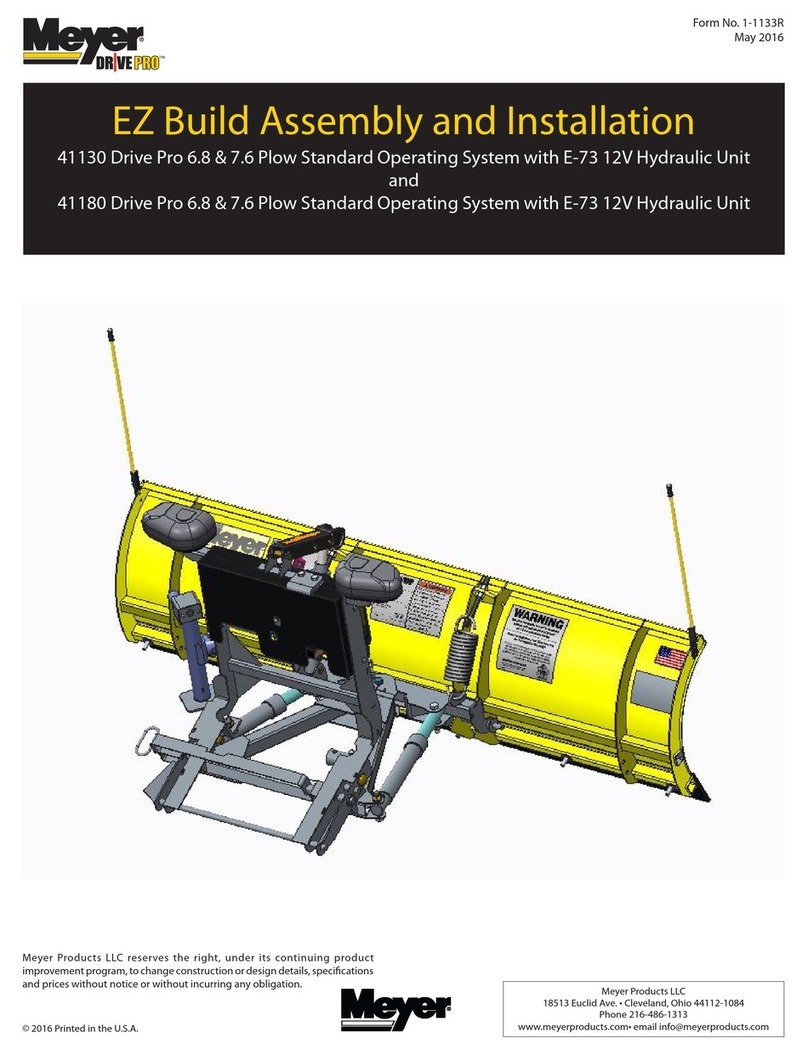
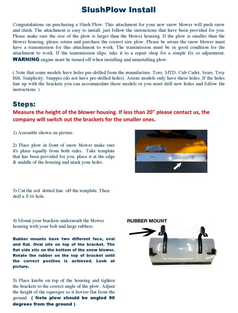
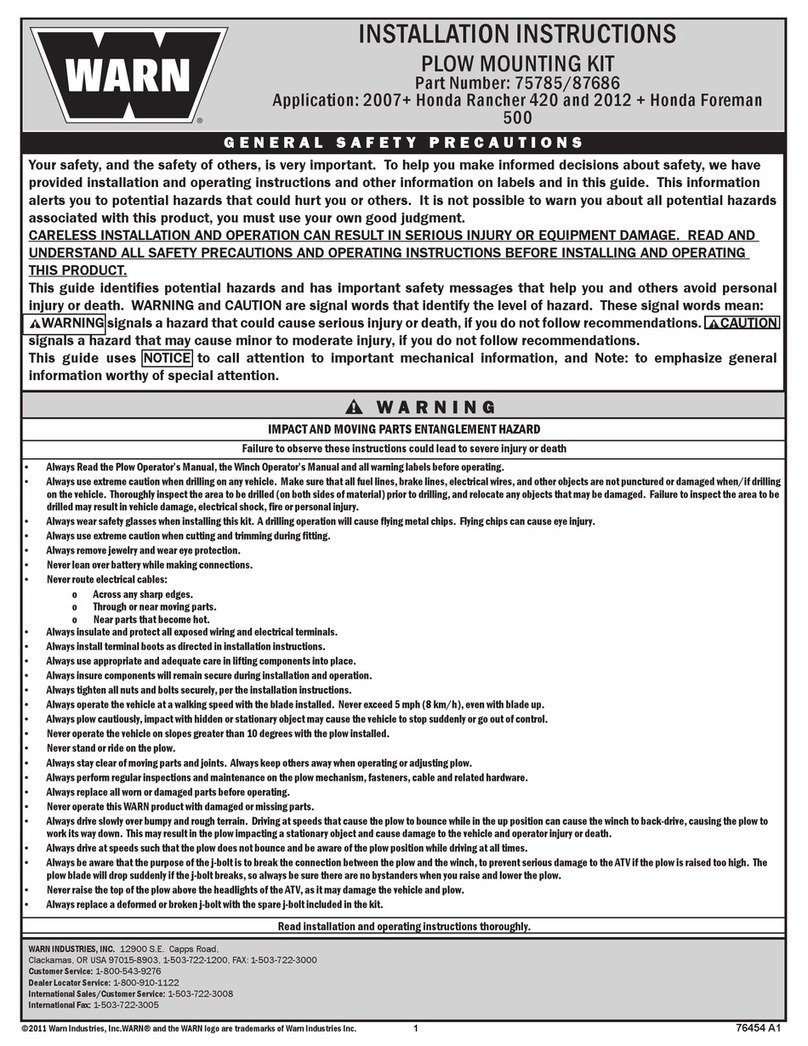
Meyer EZ-Mount Plus User manual

OPERATION and MAINTENANCE MANUAL
Insist on genuine Meyer Parts & Accessories

Snow, despite the beauty it may impart to a bleak winter landscape,
poses the dual threat of inconvenience and danger. The environmental
conditions associated with snow, not to mention the health hazards and
economic loss it may impose, seriously endanger thousands of lives
annually. Business and industry suffer, and millions of snowbelt residents
may be affected by a single snowstorm.
Meyer Products LLC has published this manual to help you get the
maximum performance from your Meyer Snow Plow and familiarize you
with the features designed for efficiency and safety; be sure you recognize
and understand them. Follow recommended operation and maintenance
instructions, so when a storm hits, your Meyer Snow Plow will be ready
and you will know how to plow like a pro. DO NOT EQUIP ANY VEHICLE
WITH A SNOW PLOW WITHOUT CONSULTING MANUFACTURERS’
RECOMMENDATIONS.
Vehicles with Meyer Snow Plows installed may be so equipped as to
meet vehicle manufacturers’ specifications and recommended options
for snow plowing use. Most vehicle manufacturers insist that vehicles
which are to be used for snow plowing be equipped with certain
options and accessories, and it is so stated in vehicle manufacturer
specifications for snow plow application.
We also recommended that, for optimum performance, vehicles used
for snow plowing be equipped with:
•FourWheelDrive
•Minimum60AmpAlternatororLarger
•Minimum70BatteryofLarger(550C.C.A.)
•MudandSnowTires
•IncreasedRadiatorCooling
•AutomaticTransmission
•PowerBrakes
•PowerSteering
Under the continuing Meyer Products Improvement Plan, Meyer Products
LLC reserves the right to change design details and construction without
prior notice and without incurring any obligation.
IMPORTANTNOTICE:InconjunctionwithFMVSS(FederalMotorVehicleStandard)andOEM(OriginalEquipmentManufacturer)guidelines,MeyerProductsLLC
has designed this plow package with the following guidelines:
CAUTION: Installation of a snowplow mat affect your ner vehicle warranty. For more information consult your Vehicle Owners’ Manual / Vehicle Dealer.
WARNING: The vehicle must not be operated when overloaded. In all cases, the loaded vehicle weight, including th entire snowplow system, all aftermarket acces-
sories,driver,passenger,options,nominaluidlevels,andcargomustnotexeedthefront/rearGrossAxleWeightRating(GAWR),andtotalGrossVehicleWeight
Rating(GVWR).Theseweightratingsarespeciedonthesafetaycompliancecerticationlabelonthedriver’ssidedooropening.Theuseofrearballastweight
may be required to prevent exceeding the front GAWR.
WARNING: Check your local/state/provincial laws regarding vehicle restrictions when the snowplow is not attached. These restrictions during specified times of the year
may require the removal of the mounting, lift frame, lift arm, hydraulic mechanism or any other fixtures or protruding surfaces mounted to the front of the vehicle.
Warning: Deployment of an air bag while using a Meyer snow plow will not be covered under Meyer Products’ warranty.
Important Information
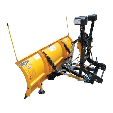

Table of Contents Page
Get to Know Your Meyer Plus Snow Plow 2-3
Plus Specifications 4
SnowPlowOperation 5
Removing&AttachingYourMeyerE-ZMountPlus™ 6-7
GeneralMaintenance&Adjustments 8-10
Diagnostic Trouble Shooting 11-18
Efficient Snow Clearance Starts with Planning 19
Keep Snow Under Control 19
SelectingProperSizeSnowPlowingEquipment 20
HourlySnowClearingCapacities 20
Plow with the Storm 21
Establishing Snow Clearance Plans 22
Snow Plowing Tips from the Pros 23
Snow Plowing in Open Areas 23
ParkingLotsandWideDriveways 24-25
StackingSnow 25
Trapped&ResidentialAreas 25
ChemicalsforSnow&IceControl 26
MeyerProductsSaltSpreaders 26-28
Meyer Accessories 29
GenuineMeyerParts 30-31
Important Information 32
Warranty Back Cover
INSIST ON GENUINE MEYER
PARTS & ACCESSORIES
• Protect your warranty
• Made to Meyer specications
• Fit right
• Wear longer
• Perform better
• Your best value
For more information visit or contact:
www.meyerproducts.com
e-mail [email protected]
SAFETY FIRST
Meyer Products recommends that this manual be read cover to cover so
that you are completely aware of all important safety recommendations.
RecordyourV-68Serialnumber.Thisnumberisprintedonthedecalunder
the hydraulic unit plastic cover.
-1-

1. Aggressor Wings, Left and Right
Made from 12 gauge Steel, 4 lazer cut vertical ribs per wing.
2. Cutting Edge - Reversible
Replaceable high carbon steel provides extra long operating life;
shouldbe1/2”abovegroundinplowingposition.(Canbehigher
whenusedongraveldriveways.)
3. Runners (optional)
Adjustable and replaceable runners hold cutting edge at proper
height.
4. Adjustable Super V Extension Springs
Tripedge give way when objects are struck at ground level. Note:
Trip spring tension should be checked on a regular basis during the
snowplow season. See Page 8 for more information.
5. Pivot Pin
Pin that attaches the wings to the A-frame.
6. A-Frame
Designed to attach the snow plow to the vehicle, to pivot moldboard
for angle plowing, and to hold plow at proper distance in front of
vehicle.
7. Power Angling Cylinders
Positions the wings hydraulically at all angles with 1-1/2 x 12” double
acting cylinders.
8. Clevis Frame
Allows snow plow assembly to be attached or detached from vehicle
in minutes.
9. Lift Frame
Allows for fast, complete removal of front end hardware, snow plow,
lights and hydraulic unit in one complete module.
10. Attaching Pins
Pull 2 blue pins to remove complete assembly.
11. Lift Arm
Dual Chain locks in position to lift snow plow. *
Warning: Lift Arm extends beyond bumper of vehicle. To minimize
damage from a front end collision, Lift Arm should be removed
from vehicle when snow plow is removed.
12. Meyer Nite Saber®Snow Plow Lights
Complies with the Federal Motor Vehicle Safety Standards.
13. Electric Hydraulic Power Unit (V-70)
Operates snow plow hydraulically- raises, lowers, angles, holds and
floats moldboard in plowing position.
14. Sno-Flo® Powder Coat
Baked on finish that looks like enamel, provides an extremely hard,
low friction surface that outlasts ordinary paint by a large margin.
Applied to all steel moldboards and mountings/frames.
15. Crankstand
Positions Moldboard and Lift Frame for easy attaching and
detaching.
Get to know your Meyer®Snowplow
-2-
* With Lift Arm all the way down, the chains should have a little slack.

-3-
V70

-4-
NOTE: Shown with optional snow deflector
SPECIFICATIONS SV-8.5 SV-9.5
WEIGHT (TOTAL) 915 lbs. 955 lbs.
HEIGHT 30.5” 30.5”
LENGTH 102” 114”
MOLDBOARD GAUGE #12 #12
VERTICAL RIBS/WING 4 4
TRIP SPRINGS 4 4
CUTTING EDGES 1/2” X 6” 1/2” X 6”
PLOWING WIDTH
AT FULL ANGLE 88” 98”
POWER ANGLING RAMS 1-1/2” x 12” Double Acting
SV2-10.5
1067 lbs.
29” to
40-1/2”
126”
#12
4
4
1/2” x 6”
109”
SV2-9.5
1015 lbs.
29” to
39-1/2”
114”
#12
4
4
1/2” x 6”
98”
SV2-8.5
983 lbs.
29” to
38-1/2”
102”
#12
4
4
1/2” x 6”
88”

HAND HELD CONTROLLER
The snow plow should only be in operation when the vehicle ignition
switch and the control switch are in the ìONî position. Care should be
taken to insure that the control switch is kept dry and free from moisture
during normal operation.
When the control switch is turned ìOn,î lights illuminate the location of
the individual touch pads for the functions of the snow plow: Up, Angle
Left,AngleRight,LeftExtend(Vonly),LeftRetract(Vonly,RightExtend
(Vonly),RightRetract(Vonly),Scoop(Vonly),Vee(Vonly)andDown.
This switch has an auto detect feature which allows it to operate either
theE-58HorV-68unit.
Lowering of the snow plow an inch at a time is possible by tapping the
down arrow in short intervals. Holding down the down arrow will activate
a float light located in the upper right corner of the control switch. This
light indicates the snow plow is now in the Lower/Float position. In this
position the snow plow will be able to follow the contour of the road and
the snow plow can also be angled to the left or right. Touching the up
arrow automatically cancels the Lower/Float position.
While angling left or right or raising the snow plow if the button is pressed
for more than six seconds the operation will be cancelled. This feature
eliminates unnecessary amp draw from the vehicle charging system.
Theautolowerbutton(ALM)whenpressedwillblinkthebacklightin
a(1)blinkpatternandallowstheplowtolowerautomaticallywhenthe
vehicle is shifted into reverse and raise automatically when shifted out
of reverse. To turn off the auto lower mode simply press the auto lower
button twice again until the back light is not flashing.
Theautoraisebutton(ARM)whenpressedtwicewillblinkthebacklight
ina(2)blinkpatternandallowstheplowtoraiseautomaticallywhenthe
vehicle is shifted into reverse and lower automatically when shifted out
of reverse. To turn off the auto raise mode simply press the auto raise
button again until the back light is not flashing.
This switch is self diagnosing. The monitor light is located in the upper
left corner next to the float light of the control switch. When the monitor
light turns on and begins to flash the control switch is sensing a problem
with a specific coil/connection on the hydraulic unit. The label below is
on the back side of your control switch.
Reset is accomplished by turning off the ignition switch or by turning
the power switch off momentarily and then back on. If the monitor light
is still illuminated after attempts to reset the switch have failed, contact
your nearest authorized Meyer Distributor for repairs.
When the controller is turned on it will activate the snow plow lights.
When the controller is turned off or removed from the harness this will
activate the vehicle headlights.
-5-
Snowplow Controller Operation
BACK/REAR TOP/FRONT
FLOAT
MODE
ON/OFF
RIGHT WING
CONTROL
AUTO V MODE
UP/DOWN
LEFT/RIGHT
SCOOP
MODE
LEFT WING
CONTROL
SYSTEMS
MONITOR

Removing and Attaching Plus Plow
DETACHING THE COMPLETE ASSEMBLY
Leave control switch in lower float position and push down on
the Lift Arm. Disconnect the electrical plug. Attach Crankstand
to the adjustment tube on the side of the A-Frame using the
chained locking pin. Caution: Crankstand must be secured
at all times. Adjust the Crankstand down until the bottom of
stand touches the ground. Pull and twist the Blue Handle Pins
to disengage lift frame from clevis frame. If the pins do not pull
easily, adjust stand up or down slightly to remove tension on
the pins until they disengage. At this time the lift frame should
be leaning forward slightly, at rest on the top of the Crankstand.
Pull truck away.
ATTACHING THE COMPLETE ASSEMBLY
Check that Blue Handle Pins are disengaged. Drive the truck
up to the EZ-Mount Plus assembly centering the hood of
the truck to the lift arm to assure proper alignment with lift
frame guide plates until contact is made. Once contact is
made, drive forward, pushing the assembly a few inches. This
insures the lift frame is square to the Clevis Frame for proper
pin attachment. Adjust the Crankstand up until the front of the
truck raises slightly. Twist Blue Handle Pins so that the small leg
re-aligns with the slot, engaging the pins. The spring loaded pins
should snap into place. Note: If pins do not lock immediately,
move truck slightly forward and/or adjust the Crankstand up
or down until pins engage, or push the top of the Lift Frame
towards the truck locking the pins to the clevis frame. Remove
the Crankstand from the A-frame by removing the chained locking
pin. Reattach the Crankstand to the transport tube on the driver’s
side of the Lift Frame in the vertical, retracted position. Caution:
Crankstand must be secured at all times. Reattach the one
step electrical connection.
-6-

Crankstand Storage To store Crankstand on the Lift Frame slide the tube that is attached to the side of the Crankstand over the receiver
tube on the driver’s side of the Lift Frame. Insert the chain locking pin through the vertical holes on both the tubes. Note: Crankstand
should always be fully retracted (up) and be pinned in the vertical transport position when not in use. Receiver Tube Cap may be
placed over the driver side transport tube while the Crankstand is in use on the A-Frame. The Receiver Tube Cap may also be switched
over to the Adjustment Tube of the A-Frame when the Crankstand is mounted to the Lift Frame. Storage of the Crankstand is the
responsibility of the operator. The stand can be stored on the lift frame in the retracted position to the driver’s side transport
tube or inside the vehicle cab.
1 Lower Plow to float position and manually push lift arm
down. Disconnect the electrical connection.
2 Remove crankstand from storage position on the
side of mount and reattach to “A” frame. Crank until
front of truck rises slightly.
3 Pull, then rotate blue pins on both sides of truck
into locked out position. The vehicle is now free
from mount and may safely back away.
1 Drive into assembly until contact is made and push
assembly a few inches forward.
REMOVAL
ATTACHMENT
2 Rotate blue pins until engaged and push top of lift
frame towards truck until pins click in place.
3 Return crankstand to storage position and
reattach the electrical connection. The mount
is now securely attached to the vehicle and
is operational.Always confirm pins are fully
engaged before over the road or snow plow
operation.
-7-
Storage position

General Maintenance
Meyer Products LLC recommends this maintenance information
for regular service. Sustained heavy operation may call for more
frequent service. Snow plowing subjects a vehicle to exceptionally
rugged use. As a result, it is very important to inspect and bring
the snow plow and vehicle up to maximum operating conditions.
Inspection should be made of both the vehicle and snowplow
prior to the plowing season and after each use.
Pre-season Maintenance
Scheduled vehicle maintenance should be performed as
recommended by the manufacturer.
Don’t forget that in addition to keeping equipment in order:
1. Keep windshield wipers, heaters and lights working.
2. Use emergency flasher lights for increased visibility and safety.
3. Equip vehicles with chains where necessary.
4. Provide operators with protective clothing and with rubber
gloves for handling snow melting chemicals.
VEHICLE ELECTRICAL SYSTEM
For maximum efficiency, the vehicle supporting the snow plow
must be properly serviced. The system should consist of at
leasta70amp./hr.batteryanda60ampalternator.Besureto
check regularly:
1. Battery terminals to assure they’re clean and free of
corrosion.
2. Electrical connections, to assure they’re tight and corrosion
free.
3. Battery must be in top operating condition.
4. Alternator and regulator, to assure maximum electrical output.
SNOWPLOW
CAUTION: ALWAYS LOWER MOLDBOARD TO THE GROUND
WHEN SNOW PLOW IS BEING SERVICED OR WHEN
VEHICLE IS NOT IN USE.
ChecktheV-70Diagnosischart,pages11-18,respectivelyand
Post Season Maintenance, page 9, for advice on maintaining
the unit.
1. Check and maintain hydraulic fluid reservoir level to Full.
Oil level should be checked with lift ram down or retracted
position.
2. Check entire hydraulic system for leaks. A significant drop in
hydraulic fluid level is evidence of a leak which must be corrected
to prevent serious damage.
3. Before and after each season, remove moldboard center pivot
pin, thoroughly grease pivot pin and reinstall. Lubricate all pivot
points with chassis lube.
4. ADJUSTING TRIP SPRING TENSION - Tighten top locknut
4 turns beyond the point when spring coils begin to separate.
Tighten bottom locknut to hold eye bolt in position as shown
in figure 1.
Figure 1
-8-

5. RUNNERS(optional)
A. Inspect moldboard runners for wear and height adjustment.
B. Always replace runners as soon as they start to wear through.
C. Adjust the runners to maintain cutting edge height of 1/2”
abovegroundinsnowplowingposition.(Canbesethigherwhen
usedongraveldriveways).
6. CUTTING EDGE - REVERSIBLE
Replace the cutting edge as soon as it appears worn. This will
prevent permanent damage to the tripedge.
7. MOUNTING BOLTS
Retighten all mounting bolts after first snow plowing session and
at regular intervals through the season.
8. SNO-FLO® POWDER COATING, both black and yellow,
should be checked at the beginning and end of each season
for any signs of rust. If any exists, use Meyer special Sno-Flo®
powder coat touch-up available in spray cans.
NOTE: PROTECTION AGAINST RUST AND CORROSION
When the power unit is not used for extended periods, protect
the chromed lift rod by fully extending and coating it with
chassis lubricant. Coat the exposed portions of the power
angling cylinder rods with chassis lubricant to protect against
corrosion.
Post Season Summer Maintenance
1. Draining & Replacing Meyer M-1 Hydraulic Fluid
Drain the fluid by removing the drain plug located on the bottom
of unit. To drain the fluid from the power angling cylinders,
disconnect the fittings and completely retract the cylinder rods
and purge cylinders and hoses of all hydraulic fluid. The complete
system should then be flushed out with Meyer M-2 Flushing Fluid
before adding new Meyer Hydraulic Fluid.
2. Meyer M-1 Hydraulic Fluid is specially formulated with
an anti-ice additive for almost constant viscosity in subzero
temperatures. Because it is free-flowing in extreme cold, the unit’s
performance and efficiency are not affected by winter weather.
It is effective for a maximum of one year. Always carry an extra
quart of Meyer M-1 Hydraulic Fluid. Use of any inferior fluids
will void the Meyer warranty.
3. Refill power unit with Meyer M-1 Hydraulic Fluid by fully
retracting lift piston and mounting cylinder and filling reservoir
to top. Note: Do not over fill unit, over filling unit will cause oil
to squirt out of the reservoir pressure relief valve. Power angling
rams should be collapsed. Install Hydraulic unit and Moldboard
assemblyonvehicle.Removereservoirpressurereliefvalve(Filler
plug).Tobleedairfromthesystempoweranglewingssidetoside
while maintaining a constant check on the reservoir fluid level.
Note: It may be necessary to bleed air from the Power angling
cylinders by loosening the hydraulic fittings. Extend and retract
wings until you have a steady stream of oil coming out of fitting.
Raise and lower the plow several times. With lift ram fully
retracted(down)checkuidlevelandreplacellerplug.
-9-

SNOW PLOW STORAGE
1. When snow plow is disconnected, disconnect lift chains
from lift arm and extend lift cylinder to end of stroke and
coat chrome rod with light grease. This fills the cylinder with
hydraulic fluid and protects the interior and exterior from rust
and corrosion.
2. Whenever Moldboard is disconnected, coat the exposed
portions of the power angling cylinder chrome rods with light
grease to protect them from corrosion.
3. Coat pivot pin and other wear points with chassis lubricant.
Be sure to grease all grease holes.
4. Unplug electical connection at power unit. Coat connection
with a dielectric compound to prevent corrosion and plug into
their corresponding weather plug.
5. Reference post season summer maintenance on page 9 prior
to final storage.
-10-

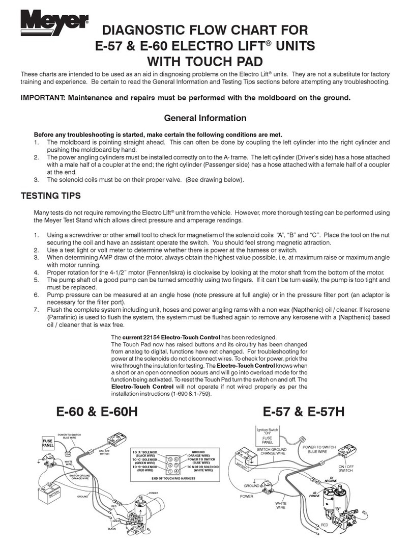
Thesechartsareintended to be usedas an aid indiagnosing problemsontheV-70Meyer HydraulicPower Units. Theyarenota
substitute for factory training and experience. Be certain to read the General Information and Testing Tips sections before attempting
any troubleshooting.
TESTING TIPS
Many tests do not require removing the Power Unit from the vehicle. However, more thorough testing can be done by using the Meyer
Test Stand which allows direct pressure and Amperage readings.
1.Useascrewdriverorothersmalltooltocheckformagnetismofsolenoidcoils(“S1,”“S2,”“S3,”“S5,”“S6”&“S7”).Placethetool
on the coil and have an assistant operate the switch. You should feel strong magnetic attraction.
2. Use a test light or volt meter to determine whether there is power at harness or Super-V controller.
3. When determining Amp draw of motor, always obtain the highest value possible, i.e., at maximum raise or angle with motor running.
4. The pump shaft of a good pump can be turned smoothly using two fingers. If it can’t be turned easily, the pump must be replaced.
6.Pumppressurecanbemeasuredatananglehose(notepressureatfullangle).
7.Ifhydraulicsystemiscontaminateditisrecommendedthatthehydraulicunit,poweranglingramsandhosesbedrainedandushed
with M-2 flush fluid. The system should then be refilled with Meyer M-1 oil. See page 9.
DIAGNOSTIC
TROUBLE SHOOTING
-11-

-12-

-13-

-14-

-15-

-16-

-17-

-18-
Table of contents
Other Meyer Snow Blower Accessories manuals

Meyer
Meyer Lot Pro 41275 Instruction Manual

Meyer
Meyer Drive Pro EZ Build 41130 Instruction Manual

Meyer
Meyer ELECTRO LIFT E-57 User manual

Meyer
Meyer TRIMLINE Series User manual

Meyer
Meyer MDII C-7.5 User manual

Meyer
Meyer Lot Pro Light Duty User manual

Meyer
Meyer Lot Pro LP-7.5 User manual

Meyer
Meyer E-Z PLUS MDII STP-7.0 User manual

Meyer
Meyer Drive Pro User manual

Meyer
Meyer Lot Pro 41675 User manual