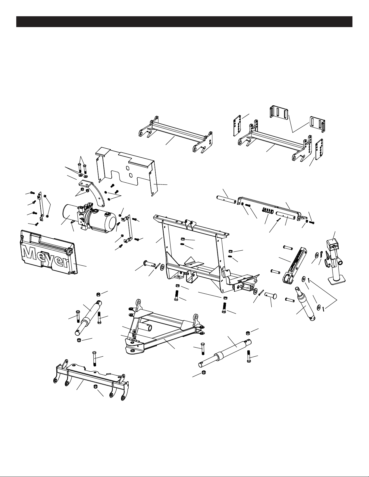
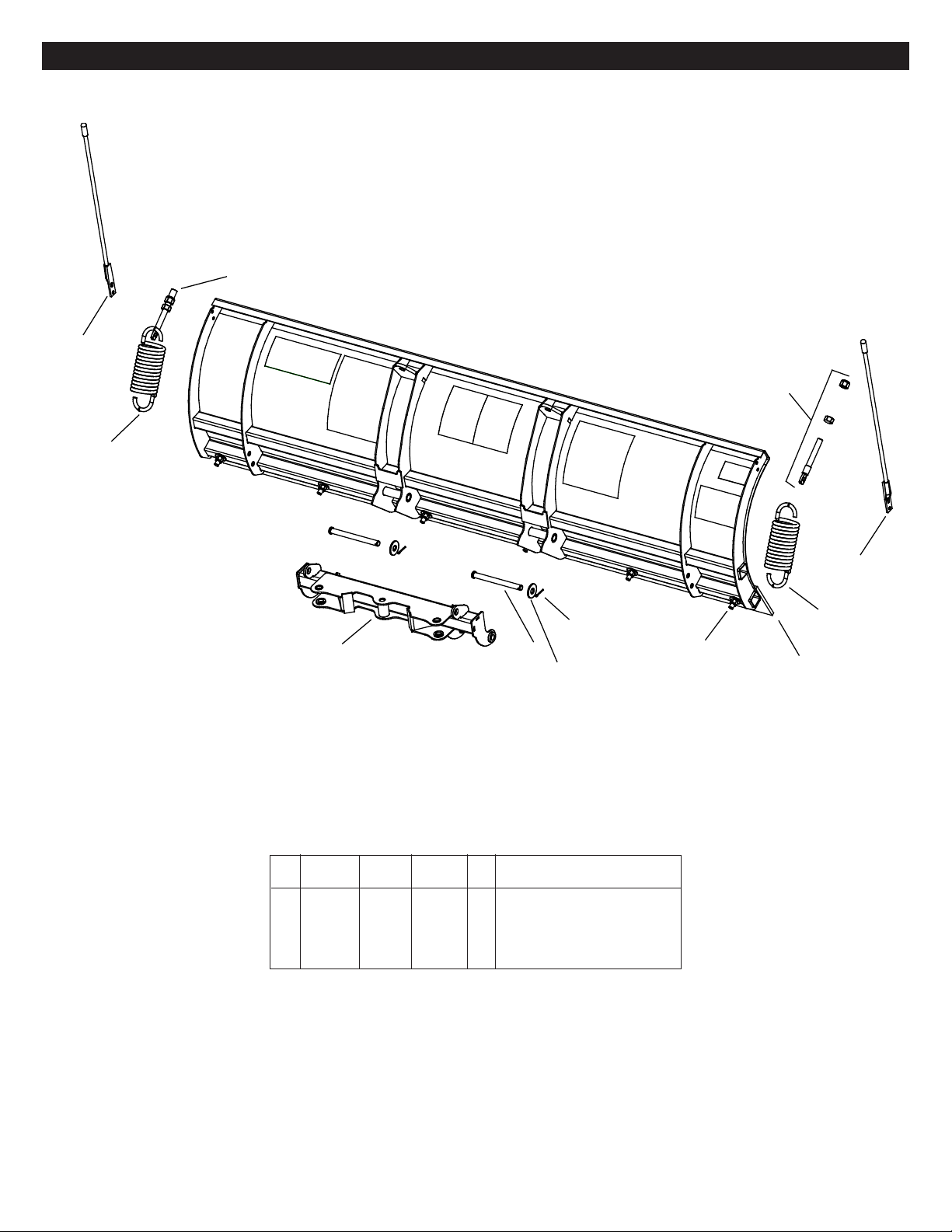
Item Part No. Part No. Qty. Description
39 20307 20307 2 • Locknut 1/2-13
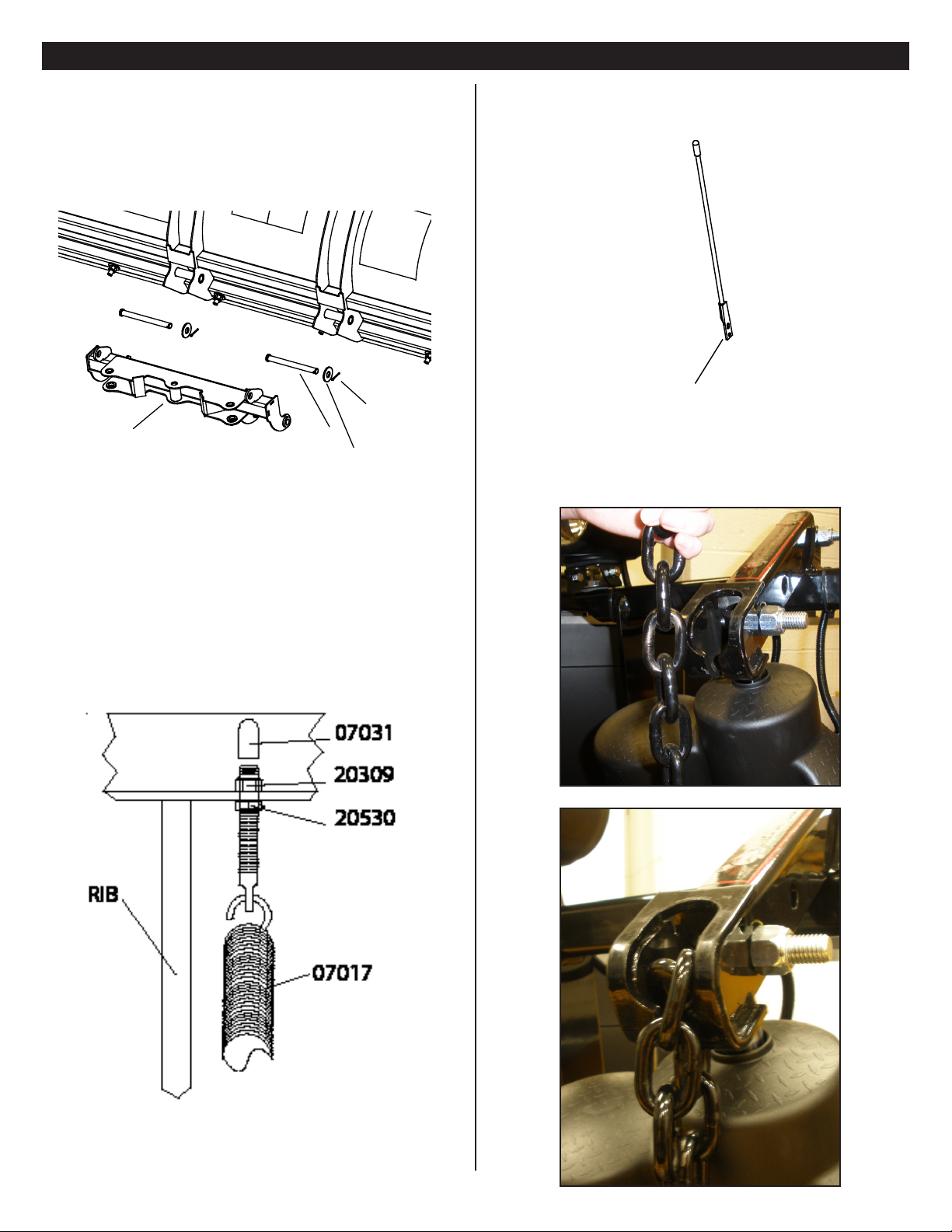
40 20530 20530 4 • 5/8-11 Finish Nut
41 22379 22379 4 • Lockwasher 3/8
42 20800 20800 1 • Quick Link 5/16”
43 21543 21543 1 • Chain 5/16” x 29”
41131 41181 1 • Accessory Box
44 23025 23025 1 •• Power Cable - 36”
45 12978 12978 2 •• Trip Spring
07810 07810 1 •• Nite Saber III Kit
09917 09917 1 •• Plow Marker Kit
46 08214 08214 2 ••• Plow Marker
47 20027 20027 4 ••• Bolt H 5/16-18 x 1 Gr. 2
48 20304 20304 4 ••• Locknut 5/16-18
49 20352 20352 8 ••• Flatwasher 5/16”
50 15220 15220 1 •• Starter Solenoid - 12 volt
51 21832 21832 1 •• Split Bushing
52 --------- 19945 2 •• Clevis Spacer
53 --------- 19948 2 •• Clevis Support Bracket
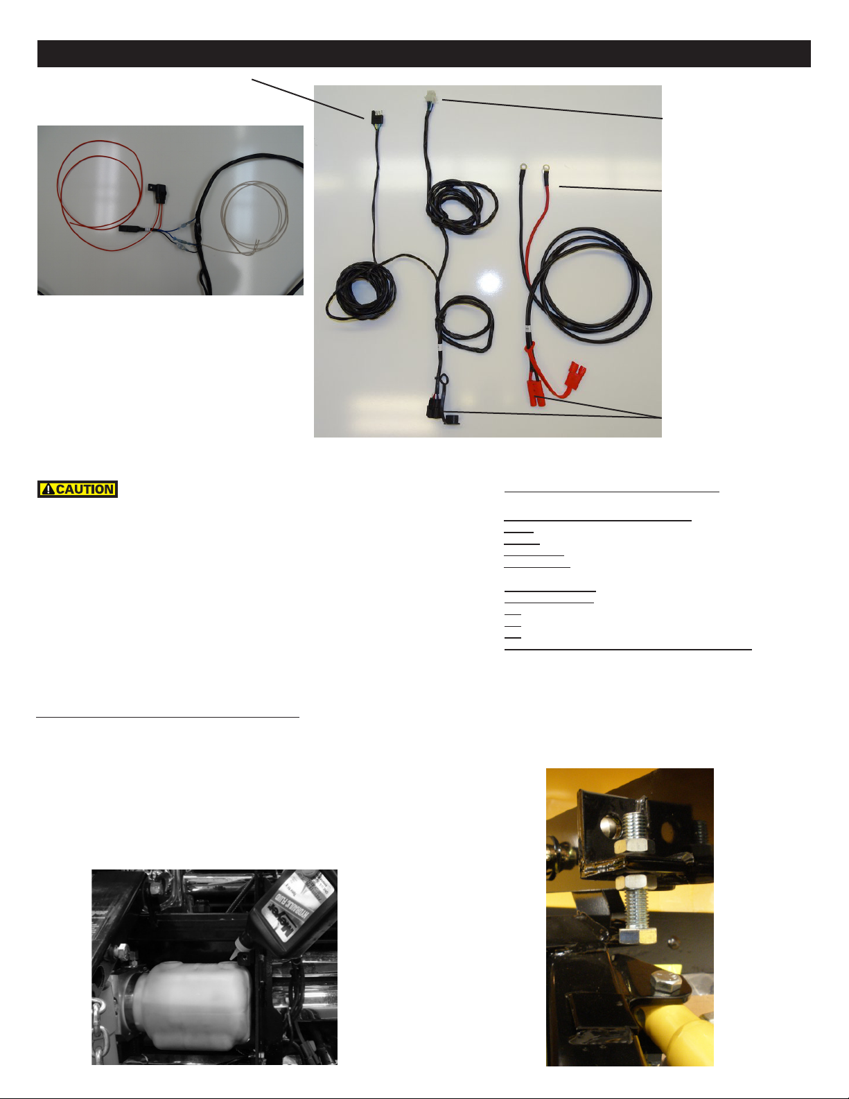
54 23022 23022 1 •• Controller
55 23033 23033 1 •• Truck Side Harness
41102 41102 1 •• Hardware Bag
56 09124 09124 2 ••• Eye Bolt
57 20357 20357 2 ••• Flatwasher 5/8”
58 20385 20385 2 ••• Cotter Pin 1/8 x 1-1/4”
59 22720 22720 2 ••• Pivot Pin 5/8 x 7
60 15187 15187 1 • Breather
61 23034 23034 1 • Keyed Ignition Relay
Parts List
Meyer Products LLC reserves the right, under its continuing product
improvement program, to change construction or design details,
specifications and prices without notice or without incurring any
obligation.
Parts indented are included in the carton, bag or assembly under which they are indented.
41130 & 41180 E-73 EZ Build
Item Part No. Part No. Qty. Description
41130 --------- 1 DP5.0- 7.5 E-73 DP Mount Assy.
--------- 41180 1 DP6.8-7.5 E-73 DP Mount Assy.
1 05888 05888 1 • Lift Ram 1-1/2 x 8”
07772 07772 1 • LH Ram with Hose & Fittings
2 05887 05887 1 •• Ram (1-1/2” x 10”)
3 22866 22866 1 •• SAE 6 x 90 Degree Elbow
4 22885 22885 1 •• Hose Assy 1/4 x 54” M-6
07783 07783 1 • RH Ram with Hose & Fittings
2 05887 05887 1 •• Ram (1-1/2” x 10”)
3 22866 22866 1 •• SAE 6 x 90 Degree Elbow
4 22921 22921 1 •• Hose Assy 1/4 x 38” M-6
5 10514 10514 1 • Lift Arm
6 14250 14250 1 • Pivot Bar Drive Pro 6.8
7 14185 14185 1 • E-73 DP Mounting Bracket
8 14232 14232 1 • A-Frame Drive Pro
9 14289 14289 1 • E-73 Lift Unit Cover Front
9a 14288 14288 1 • E-73 Lift Unit Cover Rear
10 14290 14290 2 • Lift Unit Cover Bracket
11 16024 16024 1 • E-73 Lift Ass’y. (Unit only)
12 19836 19943 1 • Clevis Drive Pro
18944 18944 1 • Lift Frame Assy DP
13 18919 18919 1 •• Lift Frame
14 19775 19775 2 •• Pin
15 18938 18938 1 •• Pull Pin
16 20406 20406 1 •• Cotter Pin 3/16 x 1-1/2”
17 22010 22010 2 •• Bolt H 3/8-16 x 1-1/4”
18 22260 22260 2 •• Poly Washer 3/8”
19 814000005 814000005 1 •• Spring
20 20144 20144 2 • Bolt H 5/8 - 11 x 2-3/4” Gr. 5
21 20147 20147 4 • Bolt H 5/8 - 11 x 3-1/2” Gr. 5
22 20309 20309 5 • Locknut 5/8 - 11
23 20331 20331 2 • Lockwasher 5/8”
24 20357 20357 3 • Flatwasher 5/8”
25 20355 20355 2 • Flatwasher 1/2”
26 20385 20385 3 • Cotter Pin 1/8 x 1-1/4”
26a 22845 22845 1 • Hair Pin
27 20420 20420 2 • Cotter Pin 1/4 x 2”
28 22000 22000 1 • Bolt H 5/8-11 x 4-1/2” Gr. 8
29 22022 22022 1 • Crankstand
30 22436 22436 2 • Pin 1 x 3”
31 23023 23023 1 • Plow Side Harness
32 22719 22719 3 • Pivot Pin 5/8 x 3”
33 22866 22866 1 • SAE Mx3/8 90 Degree Elbow
34 22884 22884 1 • Hose 1/4 x 33”
35 20027 20027 4 • Bolt H 5/16-18 x 1” Gr. 2
36 20049 20049 4 • Bolt H 3/8-16 x 1 Gr. 2
37 20100 20100 2 • Bolt H 1/2-13 x 2-3/4” Gr. 5
38 20305 20304 4 • Locknut 3/8-16
(2)
Parts Diagram